This document provides UDP helper
configuration examples.
UDP helper enables a device to convert
received UDP broadcast packets with a specific UDP destination port number into
unicast packets and forward them to a specific server on another broadcast
domain.
The configuration examples in this document
were created and verified in a lab environment, and all the devices were started
with the factory default configuration. When you are working on a live network,
make sure you understand the potential impact of every command on your network.
This document assumes that you have basic
knowledge of H3C UDP helper.
Example: Configuring
UDP helper
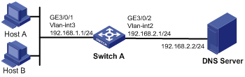
As shown in Figure
1, configure UDP helper on Switch A to forward broadcast packets with UDP
destination port number 53 from Host A and Host B to the destination DNS server
at 192.168.2.2.
Figure 1 Network diagram
To convert the broadcast packets from Host
A and Host B into unicast packets and forward them to the DNS server, specify
the IP address of the DNS server for UDP helper on VLAN-interface 3.
This configuration example was created and
verified on S12500-CMW710-R7129.
When you configure UDP helper, follow these
restrictions and guidelines:
· UDP ports 67 and 68 are used by
DHCP. Do not set UDP ports 67 and 68 for UDP helper because UDP helper cannot forward DHCP broadcast packets.
· Disabling UDP helper removes all UDP ports configured for UDP helper.
· You can configure up to 20 destination servers
on an interface.
· By default, Ethernet, VLAN, and aggregate
interfaces are shut down. You must use the undo shutdown command to bring them
up. This example assumes that all these interfaces are already up.
# Create VLAN 2 and
VLAN 3, and configure the IP addresses of VLAN interfaces. (Details not shown.)
# Enable UDP helper.
<SwitchA> system-view
[SwitchA] udp-helper enable
# Enable forwarding broadcast packets with
the UDP destination port 53.
[SwitchA] udp-helper port 53
# Specify the destination DNS server 192.168.2.2
on VLAN-interface 3.
[SwitchA] interface Vlan-interface 3
[SwitchA-Vlan-interface3] udp-helper
server 192.168.2.2
[SwitchA-Vlan-interface3] quit
# Display information about packets
forwarded by UDP helper on VLAN-interface 3.
[SwitchA] display udp-helper server
interface Vlan-interface 3
Interface name Server
VPN Server address Packets
Vlan3
192.168.2.2 5
#
vlan 2 to 3
#
udp-helper enable
udp-helper port 53
#
interface Vlan-interface2
ip address 192.168.2.1 255.255.255.0
#
interface Vlan-interface3
ip address 192.168.1.1 255.255.255.0
udp-helper server 192.168.2.2
#
interface GigabitEthernet3/0/1
port link-mode bridge
port access vlan 3
#
interface GigabitEthernet3/0/2
port link-mode bridge
port access vlan 2
#
· H3C S12500
Routing Switch Series Layer 3—IP Services Configuration Guide
· H3C S12500
Routing Switch Series Layer 3—IP Services Command Reference
 Login
Login
