This document provides examples for IPv6
address configuration.
You can use one of the following methods to
configure an IPv6 global unicast address for an interface:
· Manual configuration—The IPv6 global unicast address is manually configured.
· EUI-64 IPv6 address—The IPv6 address prefix of the interface is manually
configured. The interface identifier is generated automatically based on the MAC
address of the interface.
· Stateless address
autoconfiguration—The IPv6 global unicast
address is generated automatically based on the address prefix information
contained in the RA message. H3C S12500 switches do not support this method. They
support sending RA messages to the devices that connect to the switches, which
supports the devices to perform stateless address autoconfiguration.
· Stateful address autoconfiguration—The IPv6 address is obtained through the stateful
autoconfiguration (for example, from a DHCPv6 server).
The configuration examples in this document
were created and verified in a lab environment, and all the devices were started
with the factory default configuration. When you are working on a live network,
make sure you understand the potential impact of every command on your network.
This document assumes that you have basic
knowledge of IPv6 address configuration.
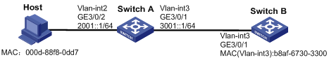
As shown in Figure
1:
· Manually configure the IPv6 global unicast addresses of VLAN-interface 2 and
VLAN-interface 3 on Switch A.
· The host uses stateless
address autoconfiguration to configure its IPv6 address
according to the RA message. Switch A advertises the RA
message in the network segment 2001::/64.
· VLAN-interface 3 on Switch B generates its
EUI-64 IPv6 address with the address prefix 3001::/64.
· The host and Switch B can reach each other.
Figure 1 Network diagram
To meet the network requirements, perform
the following tasks:
· To make sure Switch A can advertise address
prefix information in RA messages to the host, disable RA message suppression
on Switch A's interface that connects to the host. By default, the interface is
suppressed from sending RA messages.
· To make Switch B can communicate with the host
in another network segment, configure a route (a static route, in this example)
to the host on Switch B. It is not necessary to configure a route on the host
because the host uses Switch A as its default gateway.
This configuration example was created and
verified on S12500-CMW710-R7129.
# Create VLAN 2 and assign GigabitEthernet
3/0/2 to VLAN 2.
<SwitchA> system-view
[SwitchA] vlan 2
[SwitchA-vlan2] port GigabitEthernet 3/0/2
[SwitchA-vlan2] quit
[SwitchA] interface Vlan-interface 2
[SwitchA-Vlan-interface2] undo
shutdown
[SwitchA-Vlan-interface2] quit
[SwitchA] interface GigabitEthernet 3/0/2
[SwitchA-GigabitEthernet3/0/2] undo
shutdown
[SwitchA-GigabitEthernet3/0/2] quit
# Create VLAN 3 and assign GigabitEthernet
3/0/1 to VLAN 3.
[SwitchA] vlan 3
[SwitchA-vlan3] port GigabitEthernet 3/0/1
[SwitchA-vlan3] quit
[SwitchA] interface Vlan-interface 3
[SwitchA-Vlan-interface3] undo
shutdown
[SwitchA-Vlan-interface3] quit
[SwitchA] interface GigabitEthernet 3/0/1
[SwitchA-GigabitEthernet3/0/1] undo
shutdown
[SwitchA-GigabitEthernet3/0/1] quit
# Specify an IPv6 global unicast address
for VLAN-interface 2 and for VLAN-interface 3.
[SwitchA] interface Vlan-interface 2
[SwitchA-Vlan-interface2] ipv6
address 2001::1 64
[SwitchA-Vlan-interface2] quit
[SwitchA] interface Vlan-interface 3
[SwitchA-Vlan-interface3] ipv6
address 3001::1 64
[SwitchA-Vlan-interface3] quit
# Disable RA message suppression on
VLAN-interface 2.
[SwitchA] interface Vlan-interface 2
[SwitchA-Vlan-interface2] undo ipv6
nd ra halt
[SwitchA-Vlan-interface2] quit
# Create VLAN 3 and assign GigabitEthernet
3/0/1 to VLAN 3.
[SwitchB] vlan 3
[SwitchB-vlan3] port GigabitEthernet 3/0/1
[SwitchB-vlan3] quit
[SwitchB] interface Vlan-interface 3
[SwitchB-Vlan-interface3] undo
shutdown
[SwitchB-Vlan-interface3] quit
[SwitchB] interface GigabitEthernet 3/0/1
[SwitchB-GigabitEthernet3/0/1] undo
shutdown
[SwitchB-GigabitEthernet3/0/1] quit
# Configure an EUI-64 IPv6 address for VLAN-interface
3. The address prefix is 3001::/64. The interface ID is generated based on the
MAC address of the interface.
[SwitchB] interface vlan-interface 3
[SwitchB-Vlan-interface3] ipv6
address 3001:: 64 eui-64
[SwitchB-Vlan-interface3] quit
# Configure a static IPv6 route to
2001::/64 with the next hop 3001::1.
[SwitchB] ipv6 route-static 2001:: 64
3001::1
The following tasks are performed on Windows
XP:
1. Select Start and Run, and enter cmd in the Open field.
2. Execute the following
command to install IPv6:
C:\> ipv6 install
Installing...
Succeeded.
3. After the installation succeeds, verify that the network card acquires the
IPv6 link local address.
C:\> ipconfig
Windows IP Configuration
Ethernet adapter local
connection:
Connection-specific
DNS Suffix . :
IP Address. . . . . .
. . . . . . : 192.168.1.17
Subnet Mask . . . . .
. . . . . . : 255.255.255.0
IP Address. . . . . . . . . . . . : fe80::20d:88ff:fef8:dd7%6
Default Gateway . . .
. . . . . . :
In the output, the string "%6"
after the IP address indicates the sixth IPv6 interface.
You can display all IPv6 interfaces on the PC by using the ipv6 if command.
When receiving the IPv6 address prefix
2001::/64 periodically advertised by Switch A, the host automatically generates
global unicast addresses with the prefix without manual intervention.
1. Verify the IPv6 global unicast addresses
manually configured on Switch A.
# Display brief information about the
IPv6 addresses of all interfaces.
[SwitchA] display ipv6
interface brief
*down: administratively down
(s): spoofing
Interface
Physical Protocol IPv6 Address
Vlan-interface2 down
down 2001::1 [TENTATIVE]
Vlan-interface3 down
down 3001::1 [TENTATIVE]
2. Verify that the host automatically generates IPv6 global unicast addresses.
# (Method 1) Display the automatically generated IPv6 addresses on the host:
C:\> ipconfig
Windows IP Configuration
Ethernet adapter local
connection:
Connection-specific
DNS Suffix . :
IP Address. . . . . .
. . . . . . : 192.168.1.17
Subnet Mask . . . . .
. . . . . . : 255.255.255.0
IP Address. . . . . . . . . . . . : 2001::dc36:939:d072:7d3f
IP Address. . . . . . . . . . . . : 2001::20d:88ff:fef8:dd7
IP Address. . . . . . .
. . . . . : fe80::20d:88ff:fef8:dd7%6
Default Gateway . . . . . . . . . : fe80::20f:e2ff:fe00:1024%6
The output shows the following:
¡ The host generates two IPv6 global unicast addresses: 2001::DC36:939:D072:7D3F and
2001::20D:88FF:FEF8:DD7.
¡ The default gateway of the host is the link local
address of VLAN-interface 2 on Switch A, FE80::20F:E2FF:FE00:1024.
|
|
NOTE:
· After acquiring the network address prefix, Windows XP generates two global unicast
addresses. The interface ID of one address is automatically generated based on the MAC address of the interface,
while that of the other address is generated randomly. You can choose the
latter global unicast address to prevent leakage of the former interface ID.
· Windows Server 2003 does not randomly generate an interface ID.
|
# (Method 2) Display IPv6 address information for the host on Switch A.
[SwitchA] display ipv6
neighbors interface GigabitEthernet 3/0/2
Type:
S-Static D-Dynamic
IPv6 Address
Link-layer VID Interface State T Age
FE80::20D:88FF:FEF8:DD7 000d-88f8-0dd7 2 GE3/0/2 REACH D 1
2001::20D:88FF:FeF8:DD7 000d-88f8-0dd7 2 GE3/0/2 REACH D 11
3. Verify the EUI-64 IPv6 address generated on VLAN-interface 3 of Switch B.
[SwitchB] display ipv6
interface Vlan-interface 3
Vlan-interface3 current state:
DOWN
Line protocol current state:
DOWN
IPv6 is enabled, link-local
address is FE80::BAAF:67FF:FE30:3300 [TENTATIVE]
Global unicast address(es):
3001::BAAF:67FF:FE30:3300, subnet is 3001::/64 [TENTATIVE] [EUI-64]
Joined group address(es):
FF02::1
FF02::2
FF02::1:FF30:3300
MTU is 1500 bytes
ND DAD is enabled, number of
DAD attempts: 1
ND reachable time is 30000
milliseconds
ND retransmit interval is
1000 milliseconds
Hosts use stateless
autoconfig for addresses
IPv6 Packet statistics:
InReceives: 0
InTooShorts: 0
InTruncatedPkts: 0
InHopLimitExceeds: 0
InBadHeaders: 0
InBadOptions: 0
ReasmReqds: 0
ReasmOKs: 0
InFragDrops: 0
InFragTimeouts: 0
OutFragFails: 0
InUnknownProtos:
0
InDelivers: 0
OutRequests: 0
OutForwDatagrams: 0
InNoRoutes: 0
InTooBigErrors: 0
OutFragOKs: 0
OutFragCreates: 0
InMcastPkts: 0
InMcastNotMembers: 0
OutMcastPkts: 0
InAddrErrors: 0
InDiscards: 0
OutDiscards: 0
4. Verify the connectivity
between devices by using the ping command on the host, Switch A, and Switch B.
# Ping Switch A from Switch B.
[SwitchB] ping ipv6 -c 1
3001::1
PING 3001::1 : 56 data
bytes, press CTRL_C to break
Reply from 3001::1
bytes=56 Sequence=1 hop
limit=64 time = 6 ms
--- 3001::1 ping statistics
---
1 packet(s) transmitted
1 packet(s) received
0.00% packet loss
round-trip min/avg/max =
6/6/6 ms
# Ping the host from Switch B.
[SwitchB] ping ipv6 -c 1
2001::20D:88FF:FEF8:DD7
PING 2001::20D:88FF:FEF8:DD7
: 56 data bytes, press CTRL_C to break
Reply from
2001::20D:88FF:FEF8:DD7
bytes=56 Sequence=1 hop
limit=63 time = 17 ms
--- 2001::20D:88FF:FEF8:DD7
ping statistics ---
1 packet(s) transmitted
1 packet(s) received
0.00% packet loss
round-trip min/avg/max =
17/17/17 ms
Similarly, you can successfully ping Switch A and Switch B from the host, and ping Switch B and the host from Switch A.
· Switch A:
#
vlan 2 to 3
#
interface Vlan-interface2
ipv6 address 2001::1/64
undo ipv6 nd ra halt
#
interface Vlan-interface3
ipv6 address 3001::1/64
#
interface GigabitEthernet3/0/2
port link-mode bridge
port access vlan 2
#
interface GigabitEthernet3/0/1
port link-mode bridge
port access vlan 3
#
· Switch B:
#
vlan 3
#
interface Vlan-interface3
ipv6 address 3001::/64 eui-64
#
interface GigabitEthernet3/0/1
port link-mode bridge
port access vlan 3
#
ipv6 route-static 2001:: 64
3001::1
#
· H3C S12500
Routing Switch Series Layer 3—IP Services Configuration Guide
· H3C S12500
Routing Switch Series Layer 3—IP Services Command Reference
 Login
Login
