This document provides DHCP snooping
configuration examples.
DHCP snooping provides the following security features:
· Enables DHCP clients to
obtain IP addresses only from
authorized DHCP servers.
· Records IP-to-MAC mappings of DHCP clients for ARP detection and IP source guard.
DHCP snooping Option 82 records the
location information for DHCP clients. You can configure this option for the administrator
to locate the DHCP clients for security control and accounting.
The configuration examples in this document
were created and verified in a lab environment, and all the devices started
with the factory default configuration. When you are working in a live network,
make sure you understand the potential impact of every command on your network.
This document assumes that you have basic
knowledge of DHCP snooping.
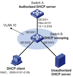
As shown in Figure
1:
· Configure DHCP snooping on Switch B to make sure
the DHCP client obtains IP addresses from only the authorized DHCP server (Switch A).
· Configure the DHCP
server to assign IP addresses
to the DHCP client from subnet 10.1.0.0/24.
· Configure ARP detection for
VLAN 10 of Switch B to check
the validity of the DHCP client based on DHCP snooping entries.
Figure 1 Network diagram
To meet the network requirements, you must
perform the following tasks:
· To allow the DHCP client to obtain an IP address
only from Switch A, configure GigabitEthernet 3/0/1 (the port connected to Switch
A) as a DHCP trusted port. By default, all ports on Switch B are untrusted
after you enable DHCP snooping.
· To enable Switch B to perform user validity
check only for terminal users, configure GigabitEthernet 3/0/1 (the port
connected to Switch A) as an ARP trusted port. By default, the interfaces in
VLAN 10 are ARP untrusted interfaces after you enable ARP detection.
· To implement ARP detection based on DHCP snooping
entries, enable GigabitEthernet 3/0/2 (the port connected to the DHCP client)
to generate DHCP snooping entries. By default, the function is disabled.
This
configuration example was created and verified on S12500-CMW710-R7129.
When you configure DHCP snooping, follow
these restrictions and guidelines:
· DHCP snooping operates between the DHCP client and DHCP server, or between the DHCP client and DHCP relay agent. It does not
operate between the DHCP server and DHCP relay agent.
· The DHCP snooping enabled device cannot act as a
DHCP server or DHCP relay agent.
· The trusted port and the port connected to the
DHCP client must be in the same VLAN.
· You can configure Layer 2 Ethernet interfaces
and Layer 2 aggregate interface as trusted interfaces.
· When a Layer 2 Ethernet
interface is added to an aggregation group, the DHCP snooping configuration on the interface does not take effect. After
the interface is removed from the
aggregation group, the configuration takes effect.
# Enable DHCP.
<SwitchA> system-view
[SwitchA] dhcp enable
# Configure DHCP address pool 1.
[SwitchA] dhcp server ip-pool 1
[SwitchA-dhcp-pool-1] network
10.1.0.0 mask 255.255.255.0
[SwitchA-dhcp-pool-1] quit
# Create VLAN 10, specify an IP address for
VLAN-interface 10, and add GigabitEthernet 3/0/1 to VLAN 10.
[SwitchA] vlan 10
[SwitchA-vlan101] port
GigabitEthernet 3/0/1
[SwitchA-vlan10] quit
[SwitchA-vlan10] interface
Vlan-interface 10
[SwitchA-Vlan-interface10] ip address
10.1.0.2 24
[SwitchA-Vlan-interface10] undo
shutdown
[SwitchA-Vlan-interface10] quit
[SwitchA] interface GigabitEthernet 3/0/1
[SwitchA-GigabitEthernet3/0/1] undo
shutdown
[SwitchA-GigabitEthernet3/0/1] quit
# Add all ports to
VLAN 10. (Details not shown.)
# Enable DHCP snooping.
<SwitchB> system-view
[SwitchB] dhcp snooping enable
# Configure GigabitEthernet 3/0/1 as
trusted.
[SwitchB] interface
GigabitEthernet3/0/1
[SwitchB-GigabitEthernet3/0/1] dhcp
snooping trust
[SwitchB-GigabitEthernet3/0/1] undo
shutdown
[SwitchB-GigabitEthernet3/0/1] quit
# Enable ARP detection.
[SwitchB] vlan 10
[SwitchB-vlan10] arp detection enable
[SwitchB-vlan10] quit
# Configure GigabitEthernet 3/0/1 as an ARP
trusted interface.
[SwitchB] interface GigabitEthernet
3/0/1
[SwitchB-GigabitEthernet3/0/1] arp
detection trust
[SwitchB-GigabitEthernet3/0/1] quit
# Enable recording of client information in
DHCP snooping entries on GigabitEthernet 3/0/2.
[SwitchB] interface
GigabitEthernet3/0/2
[SwitchB-GigabitEthernet3/0/2] dhcp
snooping binding record
[SwitchB-GigabitEthernet3/0/2] undo
shutdown
[SwitchB-GigabitEthernet3/0/2] quit
After the configuration, the DHCP client
can obtain IP addresses only from the authorized DHCP server (Switch A).
# Display information about trusted ports.
<SwitchB> display dhcp snooping
trust
DHCP Snooping is enabled.
DHCP Snooping trust becomes active.
Interface
Trusted
=========================
============
GigabitEthernet3/0/1
Trusted
The DHCP snooping device checks the
validity of ARP packets received on GigabitEthernet 3/0/2 and GigabitEthernet
3/0/3, and then performs user validity check based on DHCP snooping entries.
# Display all ARP detection-enabled VLANs.
<SwitchB> display arp detection
ARP detection is enabled in the
following VLANs:
10
# Display DHCP snooping entries.
<SwitchB> display dhcp snooping
binding
1 DHCP snooping entries found
IP Address MAC Address
Lease VLAN SVLAN Interface
=============== ==============
============ ===== ===== =================
10.1.0.3 0000-0101-010b 16907527 10 N/A GE3/0/2
· Switch A:
#
vlan 10
#
interface Vlan-interface10
ip address 10.1.0.2
255.255.255.0
#
dhcp enable
#
dhcp server ip-pool 1
network 10.1.0.0 mask
255.255.255.0
#
interface GigabitEthernet3/0/1
port link-mode bridge
port access vlan 10
#
· Switch B:
#
vlan 10
arp detection enable
#
dhcp snooping enable
#
interface GigabitEthernet3/0/1
port link-mode bridge
port access vlan 10
arp detection trust
dhcp snooping trust
#
interface GigabitEthernet3/0/2
port link-mode bridge
port access vlan 10
dhcp snooping binding record
#
interface GigabitEthernet3/0/3
port link-mode bridge
port access vlan 10
#
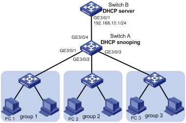
As shown in Figure
2, configure Option 82 on the DHCP snooping device to meet the following
requirements:
· Allow the DHCP server to
implement the following address allocation scheme for users in different groups:
· Allow the administrator to locate the DHCP
clients for security control and accounting.
Figure 2 Network diagram
To meet the network requirements, you must
perform the following tasks:
· To enable the DHCP snooping device to process
Option 82, configure DHCP snooping to support Option 82 on GigabitEthernet
3/0/1, GigabitEthernet 3/0/2, and GigabitEthernet 3/0/3 of Switch A.
· To enable the DHCP snooping device to add Option
82 for the DHCP server to identify where the requests are from, configure the
Option 82 circuit-ID sub-option settings on Switch A.
· To make sure the DHCP clients obtain IP
addresses only from Switch B, configure GigabitEthernet 3/0/4 (the port connected
to Switch B) as trusted. By default, all ports are untrusted on Switch A after
you enable DHCP snooping.
· To enable the DHCP server to assign a specific address
range to each group, configure DHCP user classes and dynamic IP address
allocation on the DHCP server.
· To match DHCP user classes, configure the
following hexadecimal strings as the Option 82 information on the DHCP server:
? 0x010667726F757031 for user class group1. 0106 represents the sub-option number and length, and 67726F757031 is
the hexadecimal value for group1.
? 0x010667726F757032 for user class group2. 0106 represents the sub-option number and length, and 667726F757032 is
the hexadecimal value for group2.
? 0x010667726F757033 for user class
group3. 0106 represents the sub-option number and length, and 67726F757033 is the hexadecimal value for group3.
This configuration example was created and
verified on S12500-CMW710-R7129.
When you configure DHCP snooping Option 82,
follow these restrictions and guidelines:
· DHCP snooping operates between the DHCP client and DHCP server, or between the DHCP client and DHCP relay agent. It does not operate between the DHCP server and DHCP relay agent.
· The DHCP snooping enabled device cannot act as a
DHCP server or DHCP relay agent.
· The trusted interface and the interface connected
to the DHCP clients
(GigabitEthernet 3/0/1, GigabitEthernet 3/0/2, GigabitEthernet 3/0/3) must be in
the same VLAN.
· You can configure Layer 2 Ethernet interfaces
and Layer 2 aggregate interface as trusted interfaces.
· You can configure DHCP snooping to support
Option 82 only on Layer 2 Ethernet interfaces or Layer 2 aggregate interfaces.
· When a Layer 2 Ethernet
interface is added to an aggregation group, DHCP snooping Option 82 configured on the interface does not take
effect. After the interface is removed from the aggregation group, the configuration takes
effect.
· To make Option 82 function correctly, perform Option 82 configuration
on both the DHCP server and the DHCP snooping device.
# Add all ports to VLAN 10. (Details not
shown.)
# Enable DHCP snooping.
<SwitchA> system-view
[SwitchA] dhcp snooping enable
# Configure GigabitEthernet 3/0/4 as
trusted and bring up the interface.
[SwitchA] interface GigabitEthernet
3/0/4
[SwitchA-GigabitEthernet3/0/4] dhcp snooping
trust
[SwitchA-GigabitEthernet3/0/4] undo
shutdown
[SwitchA-GigabitEthernet3/0/4] quit
# Configure DHCP snooping to support Option
82 on GigabitEthernet 3/0/1.
[SwitchA] interface GigabitEthernet
3/0/1
[SwitchA-GigabitEthernet3/0/1] dhcp snooping
information enable
# Specify the padding content for the
circuit ID sub-option as group1.
[SwitchA-GigabitEthernet3/0/1] dhcp snooping
information circuit-id string group1
[SwitchA-GigabitEthernet3/0/1] undo
shutdown
[SwitchA-GigabitEthernet3/0/1] quit
# Configure DHCP snooping to support Option
82 on GigabitEthernet 3/0/2.
[SwitchA] interface GigabitEthernet
3/0/2
[SwitchA-GigabitEthernet3/0/2] dhcp snooping
information enable
# Specify the padding content or the
circuit ID sub-option as group2.
[SwitchA-GigabitEthernet3/0/2] dhcp snooping
information circuit-id string group2
[SwitchA-GigabitEthernet3/0/2] undo
shutdown
[SwitchA-GigabitEthernet3/0/2] quit
# Configure DHCP snooping to support Option
82 on GigabitEthernet 3/0/3.
[SwitchA] interface GigabitEthernet
3/0/3
[SwitchA-GigabitEthernet3/0/3] dhcp snooping
information enable
# Specify the padding content for the
circuit ID sub-option as group3.
[SwitchA-GigabitEthernet3/0/3] dhcp snooping
information circuit-id string group3
[SwitchA-GigabitEthernet3/0/3] undo
shutdown
[SwitchA-GigabitEthernet3/0/3] quit
# Configure GigabitEthernet 3/0/1 to
operate in route mode, specify an IP address for the interface, and enable the
DHCP server on the interface.
<SwitchB> system-view
[SwitchB] interface GigabitEthernet
3/0/1
[SwitchB-GigabitEthernet3/0/1] port
link-mode route
[SwitchB-GigabitEthernet3/0/1] ip
address 192.168.10.1 24
[SwitchB-GigabitEthernet3/0/1] dhcp
select server
[SwitchB-GigabitEthernet3/0/1] undo
shutdown
[SwitchB-GigabitEthernet3/0/1] quit
# Enable DHCP.
[SwitchB] dhcp enable
# Create DHCP user class group1, and
specify a hexadecimal string for the Option 82 information used to match
against DHCP user class group1.
[SwitchB] dhcp class group1
[SwitchB-dhcp-class-group1] if-match
option 82 hex 010667726F757031
[SwitchB-dhcp-class-group1] quit
# Create DHCP user class group2, and
specify a hexadecimal string for the Option 82 information used to match
against DHCP class group2.
[SwitchB] dhcp class group2
[SwitchB-dhcp-class-group2] if-match
option 82 hex 010667726F757032
[SwitchB-dhcp-class-group2] quit
# Create DHCP user class group3, and
specify a hexadecimal string for the Option 82 information used to match
against DHCP class group3.
[SwitchB] dhcp class group3
[SwitchB-dhcp-class-group3] if-match
option 82 hex 010667726F757033
[SwitchB-dhcp-class-group3] quit
# Configure DHCP address pool office, set the duration
of the lease for assigned IP addresses, and specify the default gateway.
[SwitchB] dhcp server ip-pool office
[SwitchB-dhcp-pool-office] network
192.168.10.0 24
[SwitchB-dhcp-pool-office] address
range 192.168.10.1 192.168.10.254
[SwitchB-dhcp-pool-office] expired
day 0 hour 12
[SwitchB-dhcp-pool-office]
gateway-list 192.168.10.1
# Specify an address range for each DHCP
user class.
[SwitchB-dhcp-pool-office] class
group1 range 192.168.10.2 192.168.10.25
[SwitchB-dhcp-pool-office] class
group2 range 192.168.10.100 192.168.10.150
[SwitchB-dhcp-pool-office] class
group3 range 192.168.10.151 192.168.10.200
After the configuration, the DHCP clients
in the groups can dynamically obtain an IP address from the DHCP server.
# On PC 1, display full configuration information
at the CLI. The output shows that PC 1 in group 1 obtains IP address 192.168.10.2.
C:\>ipconfig /all
Ethernet adapter Local Area
Connection 4:
Connection-specific DNS
Suffix . :
Description . . . . . . . . .
. . : D-Link DFE-530TX PCI Fast Ethernet Adapter (rev.C) #2
Physical Address. . . . . . .
. . : 34-08-04-99-C6-B7
Dhcp Enabled. . . . . . . . .
. . : Yes
Autoconfiguration Enabled . .
. . : Yes
IP Address. . . . . . . . . . . . :
192.168.10.2
Subnet Mask . . . . . . . . .
. . : 255.255.255.0
Default Gateway . . . . . . .
. . : 192.168.10.1
DHCP Server . . . . . . . . .
. . : 192.168.10.1
DNS Servers . . . . . . . . .
. . : 192.168.100.2
Primary WINS Server . . . . .
. . : 192.168.100.3
Lease Obtained. . . . . . . .
. . : Thursday, June 06, 2013 14:06:32 PM
Lease Expires . . . . . . . .
. . : Friday, June 07, 2013 2:06:32 AM
# On PC 2, display full configuration
information at the CLI. The output shows that PC 2 in group 2 has obtained IP
address 192.168.10.100.
C:\>ipconfig /all
Ethernet adapter Local Area Connection
4:
Connection-specific DNS
Suffix . :
Description . . . . . . . . .
. . : D-Link DFE-530TX PCI Fast Ethernet Adapter (rev.C) #2
Physical Address. . . . . . .
. . : 34-08-04-FC-65-05
Dhcp Enabled. . . . . . . . .
. . : Yes
Autoconfiguration Enabled . .
. . : Yes
IP Address. . . . . . . . . . . . : 192.168.10.100
Subnet Mask . . . . . . . . .
. . : 255.255.255.0
Default Gateway . . . . . . .
. . : 192.168.10.1
DHCP Server . . . . . . . . .
. . : 192.168.10.1
DNS Servers . . . . . . . . .
. . : 192.168.100.2
Primary WINS Server . . . . .
. . : 192.168.100.3
Lease Obtained. . . . . . . .
. . : Thursday, June 06, 2013 14:06:32 PM
Lease Expires . . . . . . . .
. . : Friday, June 07, 2013 2:06:32 AM
# On PC 3, display full configuration
information at the CLI. The output shows that PC 3 in group 3 has obtained IP
address 192.168.10.151.
C:\>ipconfig /all
Ethernet adapter Local Area Connection
4:
Connection-specific DNS
Suffix . :
Description . . . . . . . . .
. . : D-Link DFE-530TX PCI Fast Ethernet Adapter (rev.C) #2
Physical Address. . . . . . .
. . : 00-0c-29-05-67-6B
Dhcp Enabled. . . . . . . . .
. . : Yes
Autoconfiguration Enabled . .
. . : Yes
IP Address. . . . . . . . . . . . :
192.168.10.151
Subnet Mask . . . . . . . . .
. . : 255.255.255.0
Default Gateway . . . . . . .
. . : 192.168.10.1
DHCP Server . . . . . . . . .
. . : 192.168.10.1
DNS Servers . . . . . . . . .
. . : 192.168.100.2
Primary WINS Server . . . . .
. . : 192.168.100.3
Lease Obtained. . . . . . . .
. . : Thursday, June 06, 2013 14:06:32 PM
Lease Expires . . . . . . . .
. . : Friday, June 07, 2013 2:06:32 AM
· Switch A:
#
vlan 10
#
dhcp snooping enable
#
interface GigabitEthernet3/0/1
port link-mode bridge
port access vlan 10
dhcp snooping information
enable
dhcp snooping information
circuit-id string group1
#
interface GigabitEthernet3/0/2
port link-mode bridge
port access vlan 10
dhcp snooping information
enable
dhcp snooping information
circuit-id string group2
#
interface GigabitEthernet3/0/3
port link-mode bridge
port access vlan 10
dhcp snooping information
enable
dhcp snooping information
circuit-id string group3
#
interface GigabitEthernet3/0/4
port link-mode bridge
port access vlan 10
dhcp snooping trust
#
· Switch B:
#
dhcp enable
#
dhcp class group1
if-match option 82 hex
010667726f757031
#
dhcp class group2
if-match option 82 hex
010667726f757032
#
dhcp class group3
if-match option 82 hex
010667726f757033
#
dhcp server ip-pool office
network 192.168.10.0 mask
255.255.255.0
address range 192.168.10.1
192.168.10.254
class group1 range
192.168.10.1 192.168.10.25
class group2 range
192.168.10.100 192.168.10.150
class group3 range
192.168.10.151 192.168.10.200
expired day 0 hour 12
gateway-list 192.168.10.1
#
interface GigabitEthernet3/0/1
port link-mode route
ip address 192.168.10.1
255.255.255.0
#
· H3C S12500 Routing
Switch Series Layer 3—IP Services Configuration Guide
· H3C S12500 Routing
Switch Series Layer 3—IP Services Command Reference
· H3C S12500 Routing
Switch Series Security Configuration Guide
· H3C S12500 Routing
Switch Series Security Command Reference
 Login
Login
