
![]() Chapters Download(415.83 KB)
Chapters Download(415.83 KB)
| Title | Size | Download |
|---|---|---|
| 07-NAT Configuration | 415.83 KB |
1.2.1 Configuring an Address Pool
1.2.3 Configuring Internal Servers
1.2.5 Configuring NAT Blacklist Attributes
1.2.6 Configuring the Aging Time of NAT Connections
1.2.7 Configuring the NAT Session Table Auto-Reset Function
1.2.8 Configuring NAT Security Logging
1.3 Displaying NAT Configuration
1.4 NAT Configuration Examples
1.4.1 NAT Configuration Example
1.4.2 NAT Internal Server Configuration Example
1.4.3 Static NAT Configuration Example
1.4.4 VPN NAT Configuration Example
1.4.5 VPN-VPN NAT Configuration Example
1.4.6 VPN NAT Configuration Example I
1.4.7 VPN NAT Configuration Example II
When configuring NAT, go to these sections for information you are interested in:
l Displaying NAT Configuration
& Note:
The line processing units (LPUs) mentioned in this chapter refer to LSB1NATB0 boards.
As described in RFC3022, network address translation (NAT) is the procedure of translating the IP address in the header of an IP data packet into another IP address. NAT is used for private networks to access public networks, and therefore saves IP address resources.
& Note:
Private IP addresses refer to the IP addresses of hosts on an intranet. Public IP addresses refer to IP addresses globally unique on the Internet.
RFC 1918 reserves the following three IP address ranges for private networks:
l Class A: from 10.0.0.0 to 10.255.255.255
l Class B: from 172.16.0.0 to 172.31.255.255
l Class C: from 192.168.0.0 to 192.168.255.255
The above IP addresses are not for use on the Internet, and users can use them within their enterprises freely without applying to the ISP or NIC.
Figure 1-1 depicts a basic NAT application.
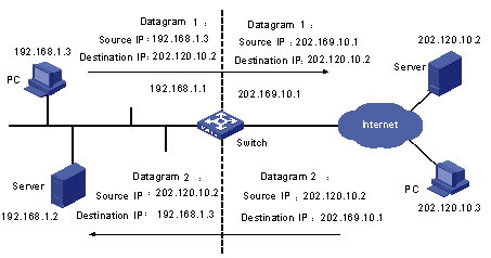
Figure 1-1 Basic NAT procedure
As shown in Figure 1-1, the switch used as a NAT device is located at the joint of the enterprise intranet and the external networks, and packets are exchanged between an internal PC and an external server as follows:
l When packet 1 sent from the internal PC with IP address 192.168.1.3 to the external server with IP address 202.120.10.2 arrives at the NAT device, the NAT process checks the packet header and finds that the packet is destined for an external site and be consistent with NAT rules. Then, the process translates the private IP address of 192.168.1.3 in the source address field of the packet header into public IP address 202.169.10.1, which can be identified on the Internet, and sends the packet out on demand while recording the address mapping in the NAT table.
l When response packet 2 sent from the external server to the internal PC with destination address 202.169.10.1 arrives at the NAT device, the NAT process checks the contents of the packet header, looks up the corresponding mapping in the NAT table, and replaces the destination address in the packet header with the private IP address of the internal PC.
The previously described NAT procedure is transparent to the communicating ends such as the internal PC and external server in Figure 1-1. The external server assumes that the IP address of the internal PC is 202.169.10.1 and does not know the address 192.168.1.3 at all. In this way, NAT ‘hides’ the enterprise intranet.
The advantage of NAT is that it enables internal hosts to access the external network resources with privacy protected. However, it has also a disadvantage: if a packet has an IP address or a port requiring NAT embedded in its header, the packet cannot be encrypted. For example, the encrypted FTP connection cannot be used; otherwise, the FTP port cannot be translated correctly.
NAT has the following features:
According to the NAT procedure illustrated in Figure 1-1, when an internal host tries to access the external networks, NAT selects a proper public address and substitutes it for the source address in the packets. In Figure 1-1, the IP address defined on the outbound interface of the NAT server is selected. In this case, only one internal host can access external networks at a time. This mode is called one-to-one NAT. When multiple internal hosts request to access external networks simultaneously, this type of NAT can only satisfy one of them.
A variation of NAT responds to concurrent requests. It allows a NAT device to be equipped with multiple public IP addresses. When the first internal host tries to access external networks, the NAT process selects a public address for it and adds a mapping record in the NAT table; when the second internal host tries to access external networks, the NAT process selects another public address, and so on. In this way, concurrent requests from multiple internal hosts are satisfied. This mode is called many-to-many NAT.
The features of the two NAT modes are described in the following table:
|
Mode |
Feature |
|
One-to-one NAT |
The NAT server has only one public IP address. Only one internal host can access external networks at a time. |
|
Many-to-many NAT |
The NAT server has multiple public IP addresses. Concurrent requests from multiple internal hosts can be satisfied. |
& Note:
l Since the probability for all internal hosts to request to access external networks is very low, the number of internal hosts can be much larger than that of public addresses for the NAT server.
l The number of public IP addresses needed depends on the statistical number of internal hosts that may request to access external networks at traffic peak.
In practice, it is possible that only some specific internal hosts are expected to have access to the Internet. That is, when the NAT process checks the header of a packet, it determines whether the included source IP address is in the address range with Internet access authority, and refuses to perform address translation for those ineligible. In a word, this involves NAT control.
Many-to-many NAT can be implemented by defining an address pool, and the control of NAT can be achieved by employing access control lists (ACLs).
An address pool is a collection of public IP addresses for NAT. Its configuration depends on the number of available public IP addresses, the number of internal hosts, and the practical application. During address translation, the NAT process selects an address from the address pool to use as the translated source address.
The control of NAT is implemented by using ACLs. Only packets matching the ACL criteria can obtain NAT service. In this way, the application of NAT is effectively controlled, making only some specific hosts have the authority to access the Internet.
NAT maps an internal IP address to an external IP address and creates a corresponding entry in the address mapping table, and the external IP address is then unavailable to any hosts other than the one currently using it if the address mapping entry does not get purged. Different from NAT, NAPT (network address port translation) is capable of mapping an IP address to multiple IP addresses or mapping a group of IP addresses to another group of IP addresses. That is, NAPT saves external address resource more efficiently. NAPT is also known as PAT (Port Address Translation) or Address Overloading.
NAPT involves the mapping of IP addresses and transport layer protocol port numbers. NAPT maps multiple sessions, each of which has its own source address, to different ports of the same external address, through which multiple internal addresses can multiplex one or more external addresses.
The following figure illustrates the fundamentals of NAPT.
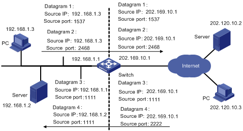
Figure 1-2 NAPT address multiplexing
As shown in the above figure, four packets containing internal addresses arrive at the switch acting as the NAPT equipment:
l Packets 1 and 2 are from the same internal address but have different source port numbers.
l Packets 3 and 4 are from different internal addresses but have the same source port number.
By using NAPT mapping, the four packets are translated into the same public address, but are given different source port numbers. In this way, the differences between the four packets are kept, and the NAT process can distinguish the response packets for each of them by destination address and port number.
With the nat outbound command configured, NAT with the Easy IP feature uses the public address of the VLAN interface on the NAT equipment as the translated source addresses. If you have only one public network IP address available or you have a limited number of internal IP addresses to be translated, you can use Easy IP to implement NAT.
NAT conceals the internal network topology and acts as a shield for internal hosts. But in practical applications, it might be required to provide some chances for external hosts to access certain internal devices such as internal WWW servers or FTP servers. By using NAT, you can flexibly add internal servers. For instance, you can use 202.169.10.10 as the public address for an internal WWW server, and 202.110.10.11 as that for an FTP server. You can even use 202.110.10.12:8080 as the public address for an internal WWW server.
If a user is not concerned about (or does not know) the port number of an internal server, you can configure the NAT AnyServer function to simplify internal server configuration. The AnyServer feature allows a public host to access all the ports of a specific protocol (ICMP provides no port information) on an internal server and thus hosts on the public network and private network can access each other. For example, a public host can use the public IP address 202.168.20.10 of an internal server to access all TCP ports on the internal server, or use the public IP address 202.168.20.11 of another internal server to access all UDP ports on it.
You can map the IP address of an internal host to a fixed public address through static NAT. For example, you can map the IP address 192.168.30.10 of an internal host to public address 202.168.30.10. Then, if the host sends packets to the public network, the source IP address in the packets will be translated to 202.168.30.10; the external hosts can also access the internal host directly using the public address 202.168.30.10.
Comparison between AnyServer and static NAT:
l The AnyServer feature can only translate packets of the specified protocol (TCP, UDP or ICMP) and is mainly used for internal hosts to provide services to the public network.
l A static NAT entry can translate TCP, UDP, and ICMP packets at the same time and is mainly used for an internal host to access the public network.
Comparision between dynamic NAT and static NAT:
l A dynamic NAT entry also defines a mapping between a private address and a public address, but it does not allow an external host to actively access the internal host, unless the internal host has already accessed the public network. Dynamic NAT entries are not fixed.
l A static NAT entry allows an external host to actively access the internal host, without affecting the internal host’s access to the public network. Static NAT entries are fixed.
The special protocols supported by NAT include Internal Control Message Protocol (ICMP), Domain Name System (DNS), Internet Locator Service (ILS), and File Transfer Protocol (FTP).
Complete the following tasks to configure NAT:
|
Task |
Remarks |
|
Required |
|
|
Required |
|
|
Required |
|
|
Required |
|
|
Required |
|
|
Optional |
|
|
Optional |
|
|
Optional |
Follow these steps to configure an address pool:
|
Use the command… |
Remarks |
|
|
Enter system view |
system-view |
— |
|
Configure an address pool |
nat address-group group-number { { start-addr end-addr [ description text ] } | description text } |
Required An address pool is a collection of consecutive public IP addresses. If its starting IP address and ending IP address are the same, there is only one address in the address pool. During address translation, the NAT server selects an IP address from the address pool to be the translated source address. |
|
Display the information about the address group |
display nat address-group [ group-number ] |
Available in any view |
![]() Caution:
Caution:
l The number of addresses included in this address pool (all the public addresses in the address pool) cannot exceed 256.
l Network segment addresses and broadcast addresses cannot be configured as the addresses of an address pool.
l Any IP address in a NAT address pool cannot be used in the internal network.
l You cannot delete an address pool associated to an ACL.
l When NAPT is enabled, there cannot be more than 32 addresses in an address pool.
Follow these steps to configure NAT:
|
To do… |
Use the command… |
Remarks |
|
Enter system view |
system-view |
— |
|
Enter VLAN interface view |
interface vlan-interface vlan-id |
— |
|
Configure one-to-one NAT |
nat outbound acl-number address-group group-number no-pat slot slot-no |
Required By configuring the association between ACLs and the NAT address pool (or the interface addresses), you can make the NAT server perform address translation for packets matching the ACL criteria only. Before a packet from the intranet is forwarded to external networks, it is first checked against the ACLs to see if it matches the translation criteria. If it does, the NAT process will find the corresponding address pool or the interface address by referring to the association, and then translate it. |
|
Configure NAPT |
nat outbound acl-number address-group group-number slot slot-no |
|
|
Configure Easy IP |
nat outbound acl-number slot slot-no |
|
|
Display the information about all mapping entries of NAT |
display nat outbound |
Available in any view |
|
Display the statistics of the current NAT information. |
display nat statistics slot slot-no |
& Note:
l As for the ACL rule which is referenced by NAT, only the source VPN, source IP address, and the destination IP address in it are used. They are also used to tell whether or not two rules conflict.
l Except for NAT log information, address translation is not performed for packets generated by the switch.
![]() Caution:
Caution:
l Do not often execute the undo nat outbound command after the configuration is stable.
l Make sure you configure the nat vpn limit command to limit the maximum number of users and connections before configuring the nat outbound command in NAPT mode.
l Currently, NAT supports only ACL source IP address and destination IP address as filtering items; other items do not take effect.
l The new ACL rule does not take effect after you configure the nat outbound command. Only the rules configured before the nat outbound command is configured takes effect. As a result, you need to configure ACL rules first, and then configure the nat outbound command.
l A VLAN interface can only be bound to one NAT LPU.
l If a VLAN interface is configured with multiple NAT rules, the device refers to the ACL numbers bound to NAT rules to determine their priorities. The bigger the ACL number, the higher the priority. The priorities of the rules in an ACL are determined by their rule numbers. The lower the number, the higher the priority.
l To enable VPN users to access the public network through NAT, you need to configure a static route with the public flag to the public network. For detail, refer to the ip route-static vpn-instance command in MPLS L3VPN Commands of the MPLS VPN Volume.
By configuring standard internal servers, you can map external addresses and ports to internal servers, enabling external hosts to access internal servers. Use the nat server command to configure the mapping table between internal servers and external hosts. The information you need to input includes: external addresses, external ports, the addresses and port numbers of the internal servers, and the service protocol.
Follow these steps to configure internal servers:
|
To do… |
Use the command… |
Remarks |
|
Enter system view |
system-view |
— |
|
Enter VLAN interface view |
interface vlan-interface vlan-id |
— |
|
Configure an internal server |
nat server protocol { tcp | udp } global global-addr global-port inside [ vpn-name ] host-addr host-port slot slot-no |
The keywords icmp, tcp, and udp can be represented by 1, 6 and 17 respectively. If the global-port and host-port arguments are set to 0 or any, AnyServers are configured. |
|
Configure a group of consecutive internal servers |
nat server protocol { tcp | udp } global global-addr global-port1 global-port2 inside [ vpn-name ] host-addr1 host-addr2 host-port slot slot-no |
|
|
Configure an AnyServer |
nat server protocol { icmp | tcp | udp } global global-addr inside [ vpn-name ] host-addr slot slot-no |
|
|
Display the information about all the internal servers |
display nat server |
Available in any view |
![]() Caution:
Caution:
l Up to 256 internal server translation commands can be configured for a VLAN interface.
l Up to 4,096 internal servers can be configured for a VLAN interface.
l Configurations for a VLAN can only be made on the same NAT LPU.
l Up to 1,024 internal server translation commands are supported by the system.
l Up to 512 AnyServers are supported by the system.
l The public address of an AnyServer cannot conflict with any interface public IP addresses or other public addresses used by NAT; the private address of an AnyServer cannot conflict with those configured in the static address translation entries or those of the servers of the same protocol.
l Do not execute the undo nat server command too often after the configuration is stable.
l Address translation is performed on the NAT LPU. Because packets sent from the private network will not be delivered to the NAT LPU by default, you need to reference QACLs on the receiving interfaces to redirect those packets to the NAT LPU. Response packets from the public network are destined to the public addresses of internal servers, and thus destination IP addresses of those packets don’t need to be configured.
l IP addresses cannot be used as VPN names. If you use IP addresses as VPN names, the CLI treats them as IP addresses uniformly.
l To enable VPN users to access the public network through NAT, you need to configure a static route with the NAT flag to the public network. For detail, refer to the ip route-static vpn-instance command in MPLS L3VPN Commands of the MPLS VPN Volume.
& Note:
l If the ICMP internal server is configured, and the public IP address is the IP address of the VLAN interface, the external public IP address will not be successfully pinged from the NAT device. The symptom does not occur to other protocol internal server.
l When the nat server command is used to configure the FTP internal server, only the private network port 21 can be used.
l A Layer-3 interface address of the switch cannot be used as the private network address of an internal server.
A static NAT entry is created using the nat static command, which includes the public network address, private network address, VPN of the private network address (if the private network address belongs to a VPN), and the slot where the NAT service board is located.
Follow these steps to configure static NAT:
|
To do… |
Use the command… |
Remarks |
|
Enter system view |
system-view |
— |
|
Enter VLAN interface view |
interface vlan-interface vlan-id |
— |
|
Configure a static NAT entry |
nat static global global-addr inside [ vpn-name ] host-addr slot slot-no |
Required |
|
Configure a group of static NAT entries |
nat static global global-addr1 global-addr2 inside [ vpn-name ] host-addr1 host-addr2 slot slot-no |
|
|
Display all static NAT entries |
display nat static |
Available in any view |
![]() Caution:
Caution:
l Up to 1,024 static address translation commands are supported by the system.
l Up to 4,096 static NAT entries are supported by the system.
l NAT configuration for a VLAN can only be made on the same NAT LPU.
l Address translation is performed on the NAT LPU. Because packets sent from the private network will not be delivered to the NAT LPU by default, you need to reference QACLs on the receiving interfaces to redirect those packets to the NAT LPU. You do not need to make specific NAT configuration for response packets from the public network because their destination public IP addresses are recorded in NAT entries.
l The public network address in a static NAT entry should globally unique.
l The public address of a static NAT entry cannot conflict with any interface IP addresses or other public addresses used by NAT.
l IP addresses cannot be used as VPN names. If you use IP addresses as VPN names, the CLI treats them as IP addresses.
l Do not remove static NAT entries too often if they operate normally.
Follow these steps to enable/disable the NAT blacklist feature on a slot:
|
To do… |
Use the command… |
Remarks |
|
Enter system view |
system-view |
— |
|
Enable the NAT blacklist feature on the specified board |
nat blacklist start |
Required Disabled by default. |
|
Set to limit the number of user connections and the rate of link set-up |
nat blacklist mode { amount | rate | all } |
Required The number of user connections and the rate of link set-up are not limited by default. |
|
Set the threshold value for the number of connections |
nat blacklist limit amount [ [ vpn-instance vpn-name ] source user-ip ] max-amount |
Required |
|
Set the global or specified threshold value for the rate of link set-up and the bucket size |
nat blacklist limit rate [ [ vpn-instance vpn-name ] source ip] cir cir-value [ cbs burst-size ] [ ebs burst-size ] |
Required By default, the threshold value for the rate of link set-up and bucket size are 250 session/s and 150 respectively. |
|
Set the specified threshold value for the rate of link set-up of the specified IP address |
nat blacklist limit rate [ vpn-instance vpn-name] source ip-address |
Required You must configure the maximum number of users and connections of the specified VPN before configuring the blacklist feature, and the number of configured blacklists must be no bigger than the maximum number of users of the VPN. |
|
Display the configuration and running status information about the blacklist |
display nat blacklist { all | [ vpn-instance vpn-name ] ip [ ip-address ] slot slot-no } |
Available in any view |
Follow these steps to configure the aging time of NAT connections:
|
To do… |
Use the command… |
Remarks |
|
Enter system view |
system-view |
— |
|
Configure the aging time of NAT connections |
nat aging-time alg time-value |
Optional By default, the aging time of NAT entries for Application Level Gateway (ALG) is 120 seconds, and that for FTP is 7,200 seconds. |
|
Display the aging time of the NAT entries of various protocols |
display nat aging-time |
Available in any view |
Follow these steps to enable the NAT session table auto-reset function:
|
To do… |
Use the command… |
Remarks |
|
Enter system view |
system-view |
— |
|
Enable the NAT session table auto-reset function |
nat auto-reset-session |
Optional Disabled by default. After you execute this command, the NAT session table is reset only when a NAT-enabled VLAN interface goes up or down. |
|
Display the status of the NAT session table auto-reset function |
display nat auto-reset-session |
Available in any view |
Follow these steps to configure NAT logging
|
To do… |
Use the command… |
Remarks |
|
Enter system view |
system-view |
— |
|
Enable the NAT logging feature |
ip userlog nat acl acl-number |
Optional The NAT logging feature is disabled on each LPU by default. |
|
Record the active time of the NAT stream log |
ip userlog nat active-time minutes |
Optional Not enabled by default. |
|
Set the address and port number of the destination server of the log export packet |
ip userlog nat export host ip-address udp-port |
Optional By default, the udp-port is 0 |
|
Set the source IP address of the log export packet |
ip userlog nat export source-ip src-address |
Optional By default, the source IP address of the log packet is 0.0.0.0. |
|
Set the version of log export packet |
ip userlog nat export version version-number |
Optional By default, the version of the log export packet is 1. |
|
Configure the server to log when a connection is established |
ip userlog nat mode flow-begin |
Optional By default, the server logs when the NAT connection is deleted. |
|
Display the configuration and statistics information of the system log feature |
display ip userlog export slot slot-no |
Available in any view |
|
To do… |
Use the command… |
Remarks |
|
Display the configuration of the address pool |
display nat address-group [ group-number ] |
Available in any view |
|
Display the aging time of NAT table entries for various protocols |
display nat aging-time |
|
|
Display the configurations and operation states of blacklists |
display nat blacklist { all | [ vpn-instance vpn-name ] ip [ ip-address ] slot slot-no } |
|
|
Display the configuration of all NATs |
display nat all |
|
|
Display the status of the NAT session table auto-reset function |
display nat auto-reset-session |
|
|
Display the configuration of all NAT associations |
display nat outbound |
|
|
Display all information about the internal servers |
display nat server |
|
|
Display all static NAT entries |
display nat static |
|
|
Display the statistics about the current NAT logging |
display nat statistics slot slot-no |
|
|
Display configurations and statistics of system logging |
display ip userlog export slot slot-no |
|
|
Display the configuration of all NATs |
display nat vpn limit { all | public | vpn-instance vpn-name } |
The clients in VLAN 100 use private network addresses to access the Internet through Switch A.
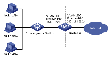
Figure 1-3 Network diagram for NAT configuration
# Create VLAN 100 and its virtual interface on the private network side, and configure an IP address for the VLAN interface.
<H3C> system-view
System View: return to User View with Ctrl+Z
[H3C] vlan 100
[H3C-vlan100] port ethernet4/1/1
[H3C-vlan100] quit
[H3C] interface Vlan-interface 100
[H3C-Vlan-interface100] ip address 10.1.1.1 255.255.255.0
[H3C-Vlan-interface100] quit
# Create VLAN 200 and its virtual interface on the public network side, and configure an IP address for the VLAN interface.
[H3C] vlan 200
[H3C-vlan200] port ethernet4/1/2
[H3C-vlan200] quit
[H3C] interface Vlan-interface 200
[H3C-Vlan-interface200] ip address 200.1.1.100 255.255.255.0
[H3C-Vlan-interface200] quit
# Configure ACL 3000.
[H3C] acl number 3000
[H3C-acl-adv-3000] rule permit ip source 10.1.1.1 0.0.0.255
[H3C-acl-adv-3000] quit
# Configure NAT address pool 0.
[H3C] nat address-group 0 200.1.1.101 200.1.1.111
# Configure a NAT binding on VLAN-interface 200. The NAT LPU is located in slot 3.
[H3C] interface Vlan-interface 200
[H3C-Vlan-interface200] nat outbound 3000 address-group 0 slot 3
[H3C-Vlan-interface200] quit
# Customize a flow template (the default flow template does not check the packet’s destination MAC address), and apply the flow template to Ethernet 4/1/1. The interface card is located in slot 4.
[H3C] flow-template user-defined slot 4 sip 0.0.0.0 dip 0.0.0.0 dmac 0-0-0 vlanid
[H3C] interface Ethernet4/1/1
[H3C-Ethernet4/1/1] flow-template user-defined
# Configure ACL 4000, allowing only the packets with VLAN ID 100 and destination MAC being the MAC address of VLAN-interface 100 (000f-e23f-3294) to pass (Only Layer 3 packets need to be redirected to the NAT LPU, while protocol packets, such as label distribution protocol (LDP) packets, and Layer 2 packets do not need to be redirected).
[H3C] acl number 4000
[H3C-acl-link-4000] rule permit ingress 100 egress 000f-e23f-3294 0-0-0
[H3C-acl-link-4000] quit
# Reference the configured ACLs to redirect the matching packets that needs address translation to the NAT LPU. Ethernet 4/1/1 is the inbound interface at the private network side, and the VLAN ID is 100.
[H3C] interface Ethernet4/1/1
[H3C-Ethernet4/1/1] traffic-redirect inbound ip-group 3000 link-group 4000 rule 0 slot 3 designated-vlan 100
[H3C-Ethernet4/1/1] quit
# Configure a blacklist.
[H3C] nat blacklist mode all
[H3C] nat blacklist limit amount 500
[H3C] nat blacklist limit rate cir 1000
[H3C] nat blacklist start
As illustrated in Figure 1-4, configure NAT to enable the two internal servers in VLAN 100 to provide services for external users.
l Host 10.1.2.2 provides WWW and Telnet services and corresponds to public network address 200.1.1.102.
l Host 10.1.2.3 provides TCP services and corresponds to public network address 200.1.1.103.

Figure 1-4 Network diagram for NAT internal server configuration
# Create VLAN 100 and its virtual interface on the private network side, and configure an IP address for the VLAN interface.
<H3C> system-view
System View: return to User View with Ctrl+Z.
[H3C] vlan 100
[H3C-vlan100] port ethernet4/1/1
[H3C-vlan100] quit
[H3C] interface Vlan-interface 100
[H3C-Vlan-interface100] ip address 10.1.2.1 255.255.255.0
[H3C-Vlan-interface100] quit
# Create VLAN 200 and its virtual interface on the public network side, and configure an IP address for the VLAN interface.
[H3C] vlan 200
[H3C-vlan200] port ethernet4/1/2
[H3C-vlan200] quit
[H3C] interface Vlan-interface 200
[H3C-Vlan-interface200] ip address 200.1.1.100 255.255.255.0
[H3C-Vlan-interface200] quit
# Configure ACL 3000.
[H3C] acl number 3000
[H3C-acl-adv-3000] rule permit ip source 10.1.2.1 0.0.0.255
[H3C-acl-adv-3000] quit
# Configure internal servers on VLAN-interface 200. The NAT LPU is located in slot 3.
[H3C] interface Vlan-interface 200
[H3C-Vlan-interface200] nat server protocol tcp global 200.1.1.102 www inside 10.1.2.2 www slot 3
[H3C-Vlan-interface200] nat server protocol tcp global 200.1.1.102 telnet inside 10.1.2.2 telnet slot 3
[H3C-Vlan-interface200] nat server protocol tcp global 200.1.1.103 any inside 10.1.2.3 any slot 3
[H3C-Vlan-interface200] quit
# Define a flow template (the default flow template does not check the packet’s destination MAC address), and apply the flow template to Ethernet 4/1/1. The interface card is located in slot 4.
[H3C] flow-template user-defined slot 4 sip 0.0.0.0 dip 0.0.0.0 dmac 0-0-0 vlanid
[H3C] interface Ethernet4/1/1
[H3C-Ethernet4/1/1] flow-template user-defined
# Configure ACL 4000, allowing only the packets with VLAN ID 100 and destination MAC being the MAC address of VLAN-interface 100 (000f-e23f-3294) to pass (Only Layer 3 packets need to be redirected to the NAT LPU, while protocol packets and Layer 2 packets do not need to be redirected).
[H3C] acl number 4000
[H3C-acl-link-4000] rule permit ingress 100 egress 000f-e23f-3294 0-0-0
[H3C-acl-link-4000] quit
# Reference the configured ACLs to redirect the matching packets that needs address translation to the NAT LPU. Ethernet 4/1/1 is the inbound interface at the private network side, and the VLAN ID is 100.
[H3C] interface Ethernet4/1/1
[H3C-Ethernet4/1/1] traffic-redirect inbound ip-group 3000 link-group 4000 rule 0 slot 3 designated-vlan 100
[H3C-Ethernet4/1/1] quit
As illustrated in Figure 1-5, configure static NAT to enable the two hosts in VLAN 100 to access the public network using fixed IP addresses.
l Host 10.1.3.2 corresponds to public network address 200.1.1.102.
l Host 10.1.3.3 corresponds to public network address 200.1.1.103.
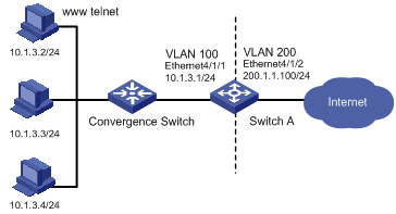
Figure 1-5 Network diagram for static NAT configuration
# Create VLAN 100 and its virtual interface on the private network side, and configure an IP address for the VLAN interface.
<H3C> system-view
System View: return to User View with Ctrl+Z.
[H3C] vlan 100
[H3C-vlan100] port ethernet4/1/1
[H3C-vlan100] quit
[H3C] interface Vlan-interface 100
[H3C-Vlan-interface100] ip address 10.1.3.1 255.255.255.0
[H3C-Vlan-interface100] quit
# Create VLAN 200 and its virtual interface on the public network side, and configure an IP address for the VLAN interface.
[H3C] vlan 200
[H3C-vlan200] port ethernet4/1/2
[H3C-vlan200] quit
[H3C] interface Vlan-interface 200
[H3C-Vlan-interface200] ip address 200.1.1.100 255.255.255.0
[H3C-Vlan-interface200] quit
# Configure ACL 3000.
[H3C] acl number 3000
[H3C-acl-adv-3000] rule permit ip source 10.1.3.1 0.0.0.255
[H3C-acl-adv-3000] quit
# Configure static NAT entries on VLAN-interface 200. The NAT LPU is located in slot 3.
[H3C] interface Vlan-interface 200
[H3C-Vlan-interface200] nat static global 200.1.1.102 inside 10.1.3.2 slot 3
[H3C-Vlan-interface200] nat static global 200.1.1.103 inside 10.1.3.3 slot 3
[H3C-Vlan-interface200] quit
# Define a flow template (the default flow template does not check the packet’s destination MAC address), and apply the flow template to Ethernet 4/1/1. The interface card is located in slot 4.
[H3C] flow-template user-defined slot 4 sip 0.0.0.0 dip 0.0.0.0 dmac 0-0-0 vlanid
[H3C] interface Ethernet4/1/1
[H3C-Ethernet4/1/1] flow-template user-defined
# Configure ACL 4000, allowing only the packets with VLAN ID 100 and destination MAC being the MAC address of VLAN-interface 100 (000f-e23f-3294) to pass (Only Layer 3 packets need to be redirected to the NAT LPU, while protocol packets and Layer 2 packets do not need to be redirected).
[H3C] acl number 4000
[H3C-acl-link-4000] rule permit ingress 100 egress 000f-e23f-3294 0-0-0
[H3C-acl-link-4000] quit
# Reference the configured ACLs to redirect the matching packets that needs address translation to the NAT LPU. Ethernet 4/1/1 is the inbound interface at the private network side, and the VLAN ID is 100.
[H3C] interface Ethernet4/1/1
[H3C-Ethernet4/1/1] traffic-redirect inbound ip-group 3000 link-group 4000 rule 0 slot 3 designated-vlan 100
[H3C-Ethernet4/1/1] quit
As shown in Figure 1-6:
Corporation A and Corporation B use the same private network addresses, and they are connected to the PE through VLAN 100 and VLAN 101 respectively to access the Internet. VLAN 100 is bound to VPN-a, and VLAN 101 is bound to VPN-b. Address translation must be performed before the two corporations can access the Internet.
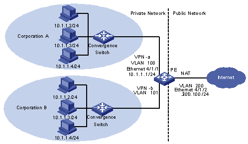
Figure 1-6 Network diagram for distributed NAT configuration
1) Configure Corporation A
# Create VPN-a.
For detailed configuration information, refer to Configuring PE Router in MPLS L3VPN Configuration of the MPLS VPN Volume.
# Configure a static route for VPN-a so that there is a route between the private network and the public network on the PE. Specify 200.1.1.1 as the next hop for PE (directly connected to the outbound interface of VLAN 200) on the public network side.
<H3C> system-view
[H3C] sysname PE
[PE] ip route-static vpn-instance VPN-a 0.0.0.0 0 200.1.1.1 public
# Create VLAN 100 and its virtual interface, bind VLAN-interface 100 to VPN-a and configure an IP address for the VLAN interface.
[PE] vlan 100
[PE-vlan100] port ethernet4/1/1
[PE-vlan100] quit
[PE] interface vlan-interface 100
[PE-vlan-interface100] ip binding vpn-instance VPN-a
[PE-vlan-interface100] ip address 10.1.1.1 255.255.255.0
[PE-vlan-interface100] quit
# Create VLAN 200 and its virtual interface, and configure an IP address for the VLAN interface.
[PE] vlan 200
[PE-vlan200] port ethernet4/1/2
[PE-vlan200] quit
[PE] interface Vlan-interface 200
[PE-Vlan-interface200] ip address 200.1.1.100 255.255.255.0
# Configure ACL 3000.
[PE] acl number 3000
[PE-acl-adv-3000] rule permit ip vpn-instance VPN-a source 10.1.1.1 0.0.0.255
[PE-acl-adv-3000] quit
# Configure the maximum numbers of users and connections of VPN-a.
[PE] nat vpn limit vpn-instance VPN-a 1000 500000
# Configure a NAT address pool with the identifier of 0.
[PE] nat address-group 0 200.1.1.101 200.1.1.111
# Bind ACL 3000 to address group 0 on VLAN-interface 200.
[PE] interface Vlan-interface 200
[PE-Vlan-interface200] nat outbound 3000 address-group 0 slot 3
[PE-Vlan-interface200] quit
# Customize a flow template (the default flow template does not check the packet’s destination MAC address), and apply the flow template to Ethernet 4/1/1. The interface card is located in slot 4.
[PE] flow-template user-defined slot 4 sip 0.0.0.0 dip 0.0.0.0 dmac 0-0-0 vlanid
[PE] interface Ethernet4/1/1
[PE-Ethernet4/1/1] flow-template user-defined
# Configure ACLs for packet redirection. You are recommended to configure two ACLs: ACL 4000 and ACL 3001. ACL 4000 allows only the packets with VLAN ID 100 and DMAC being the MAC address of VLAN-interface 100 (000f-e23f-3294) to pass (only Layer 3 packets need to be redirected to the NAT LPU for address translation, while protocol packets, such as LDP packets, and Layer 2 packets do not need to be redirected). ACL 3001 allows the packets with source IP address 10.1.1.0/24 to pass.
[PE] acl number 4000
[PE-acl-link-4000] rule permit ingress 100 egress 000f-e23f-3294 0-0-0
[PE-acl-link-4000] quit
[PE] acl number 3001
[PE-acl-adv-3001] rule permit ip source 10.1.1.0 0.0.0.255
[PE-acl-adv-3001] quit
# Reference the ACLs to redirect the packets that needs address translation to the NAT LPU. Ethernet 4/1/1 is the inbound interface on the private network side, and the VLAN ID is 100.
![]() Caution:
Caution:
You need to bind VLAN-interface 100 to VPN-a before referencing the ACLs for packet redirection on the private network side.
[PE]interface Ethernet4/1/1
[PE-Ethernet4/1/1]traffic-redirect inbound ip-group 3001 link-group 4000 rule 0 slot 3 designated-vlan 100
[PE-Ethernet4/1/1] quit
2) Configure Corporation B
The configuration procedure is similar to that of Corporation A.
# Configure the blacklist.
[PE] nat blacklist mode all
[PE] nat blacklist limit amount 500
[PE] nat blacklist limit rate cir 1000
[PE] nat blacklist start
As shown in Figure 1-7:
l In VPN 1, some clients use the public network addresses that belong to the network segment 200.1.1.0/24, and some clients use the private network addresses that belong to the network segment 192.168.1.0/24.
l In VPN 1, clients using the public network addresses can access the public network through Internet-VPN attached to PE 2, while clients using the private network addresses need address translation before they can access the public network.
l The clients in VPN 1 are connected to PE 1 through Ethernet 4/1/1, in which a type B LPU is inserted. Ethernet 4/1/1 belongs to VLAN 192.
l PE 1 is connected to the MPLS network through Ethernet 5/1/1, in which a type C LPU is inserted. Ethernet 5/1/1 belongs to VLAN 100.
l Because the type B LPU cannot forward MPLS packets, you need to redirect MPLS packets to the type C LPU for label encapsulation and forwarding. Refer to MPLS Hybrid Insertion Configuration in the MPLS VPN Volume for detailed information.
l There is a route from VPN 1 to the public network in the routing table of PE 1.
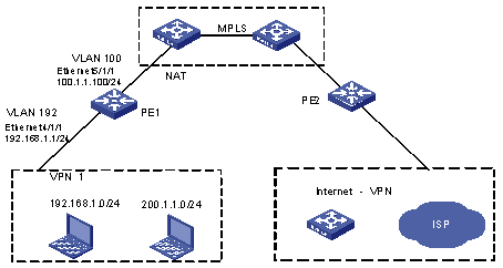
Figure 1-7 Network diagram for VPN-VPN NAT configuration
1) Configure PE 1
# Create VPN 1.
For detailed configuration information, refer to the section Configuring PE Router in MPLS L3VPN Configuration of the MPLS VPN Volume.
# Create VLAN 192 and its VLAN interface and bind the VLAN interface to VPN 1. Configure an IP address for the VLAN interface.
[PE1] vlan 192
[PE1-vlan192] port ethernet4/1/1
[PE1-vlan192] quit
[PE1] interface vlan-interface 192
[PE1-vlan-interface192] ip binding vpn-instance VPN1
[PE1-vlan-interface192] ip address 192.168.1.1 255.255.255.0
[PE1-vlan-interface192] quit
# Create VLAN 100 and its VLAN interface, and configure an IP address for the VLAN interface.
[PE1] vlan 100
[PE1-vlan100] port ethernet5/1/1
[PE1-vlan100] quit
[PE1] interface vlan-interface 100
[PE1-Vlan-interface100] ip address 100.1.1.100 24
# Configure BGP and MPLS. Refer to the section Configuring PE Router in MPLS L3VPN Configuration of the MPLS VPN Volume for detailed configuration information.
# Customize a flow template, and then apply it to Ethernet 4/1/1, where 4 indicates the slot in which the LPU is located.
[PE1] flow-template user-defined slot 4 sip 0.0.0.0 dip 0.0.0.0 dmac 0-0-0 vlanid
[PE1]interface Ethernet4/1/1
[PE1-Ethernet4/1/1]flow-template user-defined
# Configure the ACLs for packet redirection. You need to configure two ACLs: ACL 4000 and ACL 3001. ACL 4000 allows only Layer 3 packets to be redirected (only Layer 3 packets need to be redirected to the NAT LPU for translation, while protocol packets, such as LDP packets, and local Layer 2 packets do not need to be redirected). 000f-e23f-3294 is the MAC address of the Layer 3 interface on PE 1. ACL 3001 is used for redirecting packets to the NAT LPU.
[PE1]acl number 4000
[PE1-acl-link-4000] rule permit ingress 192 egress 000f-e23f-3294 0-0-0
[PE1-acl-link-4000] quit
[PE1] acl number 3001
[PE1-acl-adv-3001] rule permit ip source 192.168.1.0 0.0.0.255
[PE1-acl-adv-3001] quit
# Configure ACL 3000.
[PE1] acl number 3000
[PE1-acl-adv-3000] rule permit ip source 200.1.1.0 0.0.0.255
[PE1-acl-adv-3000] quit
# Reference ACL 3000 to redirect packets that need address translation to LPU in slot 5.
[PE1]interface Ethernet4/1/1
[PE1-Ethernet4/1/1]traffic-redirect inbound ip-group 3000 rule 0 link-group 4000 interface Ethernet5/1/2 192 l3-vpn
# Reference ACL 3001 to redirect the packets that need to be translated to the NAT LPU. The NAT LPU is located in slot 3.
![]() Caution:
Caution:
You need to bind VLAN 192 to VPN 1 before referencing an ACL for packet redirection on the private network side.
[PE1] interface Ethernet4/1/1
[PE1-Ethernet4/1/1] traffic-redirect inbound ip-group 3001 link-group 4000 rule 0 slot 3 designated-vlan 192
# Configure an ACL rule to be referenced by NAT.
[PE1] acl number 3100
[PE1-acl-adv-3100] rule permit ip vpn-instance VPN1 source 192.168.1.0 0.0.0.255
[PE1-acl-adv-3100] quit
# Configure the maximum number of users and the maximum number of connections in VPN 1.
[PE1] nat vpn limit vpn-instance VPN1 1000 500000
# Configure a NAT address pool 0.
[PE1] nat address-group 0 100.1.2.101 100.1.2.111
# Configure NAT binding on VLAN-interface 100.
[PE1] interface vlan-interface 100
[PE1-Vlan-interface100] nat outbound 3100 address-group 0 slot 3
[PE1-Vlan-interface100] quit
# Use BGP to advertise the route corresponding to the address pool to PE 2.
[PE1] bgp 100
[PE1-bgp] ipv4-family vpn-instance VPN1
[PE1-bgp-af-vpn-instance] import-route nat
& Note:
Choose one of the following three methods to advertise the VPN routes (the first method is recommended):
l Execute the export route-policy command in VPN instance view to advertise the routes configured with public network addresses, and then execute the import direct command to import directed connected routes in BGP view.
l Execute the filter-policy export command in BGP VPNv4 subaddress family view to filter out the routes configured with private network addresses and advertise the routes configured with public network addresses. Then, execute the import direct command in BGP VPN instance subaddress family view to import directed connected routes.
l Execute the network command in BGP VPN instance subaddress family view to advertise the routes.
You can choose one of the following two methods to advertise the NAT public route (the first method is recommended):
l Execute the import nat command in BGP VPN instance subaddress family view to advertise the NAT routes.
l Execute the network command in BGP VPN instance subaddress family view to advertise the NAT routes.
As illustrated in Figure 1-8 CE 1 and CE 2 are connected to a PE and belong to VPN 1 and VPN 2 respectively.
l Hosts in VPN 1 and VPN 2 use both public and private IP addresses, and the private addresses in the two VPNs overlap.
l By configuring NAT, all hosts (including those using private IP addresses) in VPN 1 can access the public IP addresses in VPN 2 (while hosts in VPN 2 cannot access the private IP addresses in VPN 1).
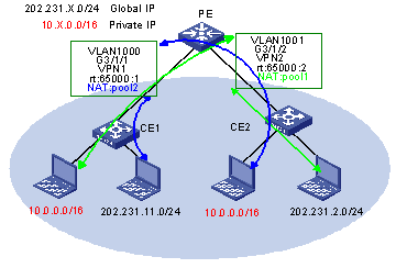
Figure 1-8 Network diagram for VPN NAT configuration
1) Configure PE
l Create VPN 1, configure a routing policy to advertise the public network segment 202.0.0.0/8,but not the private network segment 10.0.0.0/8, and redistribute routes from VPN 2.
l Create VLAN 1000 for VPN 1, bind VLAN-interface 1000 to VPN 1, and configure the IP address of VLAN-interface 1000.
l Create VPN 2, configure a routing policy to advertise the public network segment 202.0.0.0/8 but not the private network segment 10.0.0.0/8, and redistribute routes from VPN 1.
l Create VLAN 1001 for VPN 2, bind VLAN-interface 1001 to the VPN, and configure the IP address of VLAN-interface 1001.
l Configure a routing protocol (OSPF, BGP, ISIS or static routing), enabling the PE and CEs to learn routes from each other.
l On PE’s VLAN-interface 1001 that connects to CE 2, configure a NAT address pool for hosts in VPN 1.
l On PE’s VLAN-interface 1000 that connects to CE 1, configure a NAT address pool for hosts in VPN 2.
l Configure QACL redirection on the interface of VPN 1 to redirect packets from VPN 1 that need address translation to the NAT board.
l Configure QACL redirection on the interface of VPN 2 to redirect packets from VPN 2 that need address translation to the NAT board.
2) Configure CE1
Configure the routing protocol on CE 1.
3) Configure CE2
Configure the routing protocol on CE 2.
1) Configure PE
# Create VPN 1, and configure VPN 1 to redistribute routes from VPN 2.
<PE> system-view
[PE] ip vpn-instance VPN1
[PE-vpn-VPN1] route-distinguisher 65000:1
[PE-vpn-VPN1] vpn-target 65000:2 import-extcommunity
[PE-vpn-VPN1] quit
# Configure an ACL to permit public network 202.0.0.0/8.
[PE] acl number 2013
[PE-acl-basic-2013] rule permit source 202.0.0.0 0.255.255.255
[PE-acl-basic-2013] quit
# Configure a routing policy to advertise only the network 202.0.0.0/8.
[PE] route-policy vpn1 permit node 0
[PE-route-policy] if-match acl 2013
[PE-route-policy] apply extcommunity rt 65000:1
[PE-route-policy] quit
[PE] ip vpn-instance VPN1
[PE-vpn-VPN1] export route-policy vpn1
# Create VLAN 1000, and bind VLAN-interface 1000 to VPN 1.
[PE] vlan 1000
[PE-vlan1000] port GigabitEthernet 3/1/1
[PE-vlan1000] quit
[PE] interface vlan-interface 1000
[PE-Vlan-interface1000] ip binding vpn-instance VPN1
[PE-Vlan-interface1000] ip address 202.231.11.1 255.255.255.0
[PE-Vlan-interface1000] ip address 10.0.1.254 255.255.255.0 sub
[PE-Vlan-interface1000] quit
Note: Configurations of VPN 2 are similar to that of VPN 1 and thus omitted.
# Configure a routing protocol.
Select a routing protocol based on actual needs.
# Configure an ACL. To apply this ACL to VPN 1, you need to specify VPN 1 in the rule.
[PE] acl number 3000
[PE-acl-adv-3000] rule permit ip vpn-instance VPN1 source 10.0.0.0 0.0.0.255
[PE-acl-adv-3000] quit
# Configure NAT address pool 100.
[PE] nat address-group 100 202.231.1.100 202.231.1.110
# Configure the maximum numbers of users and connections allowed in VPN 1 (set the values based on the actual number of hosts in VPN 1).
[PE] nat vpn limit vpn-instance VPN1 1000 100000
# Apply NAT address pool 100 to VLAN-interface 1001 that connects to CE 2.
[PE] interface vlan-interface 1001
[PE-Vlan-interface1001] nat outbound 3000 address-group 100 slot 6
[PE-Vlan-interface1001] quit
# Create an ACL, and apply it to the interface of VPN 1 to redirect packets that need address translation to the NAT board. The ACL rule cannot contain VPN 1 but must contain the VLAN ID 1000.
[PE] acl number 3001
[PE-acl-adv-3001] rule permit ip source 10.0.0.1 0.0.0.255
[PE-acl-adv-3001] quit
[PE] interface GigabitEthernet 3/1/1
[PE-GigabitEthernet3/1/1] traffic-redirect inbound ip-group 3001 slot 6 designated-vlan 1000
[PE-GigabitEthernet3/1/1] quit
# Configurations on VPN 2 are similar to that on VPN 1 and thus omitted.
2) Configure CE
Configure a Layer 3 routing protocol on the CE. The configuration procedure is omitted.
l As illustrated in Figure 1-9, CE 1 and CE 2 are connected to a PE and belong to VPN 1 and VPN 2 respectively.
l The private IP addresses of the hosts in VPN 1 and VPN 2 may overlap.
l By configuring NAT, all hosts in VPN 2 can access the specified internal server in VPN 1. The IP address of the internal server is a private network address that may overlap with an address in VPN 2.
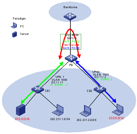
Figure 1-9 Network diagram for VPN NAT configuration
1) Configure PE
l Create VPN 1, configure a routing policy to advertise the public network segment 202.0.0.0/8 but not the private network segment 10.0.0.0/8, and redistribute routes from VPN 2.
l Create VLAN 1000 for VPN 1, bind VLAN-interface 1000 to the VPN, and configure the IP address of VLAN-interface 1000.
l Create VPN 2, configure a routing policy to advertise public network segment 202.0.0.0/8 but not the private network segment 10.0.0.0/8, and redistribute routes from VPN 1.
l Create VLAN 1001 for VPN 2, bind VLAN-interface 1001 to the VPN, and configure the IP address of VLAN-interface 1001.
l Configure a routing protocol (OSPF, BGP, ISIS or static routing), enabling the PE and CEs to learn routes from each other.
l Configure a NAT address pool for hosts in VPN 1 on VLAN-interface 100 that connects to the backbone.
l Configure the NAT internal server mapping of VPN1 on VLAN-interface 100 that connects to the backbone.
l Configure a NAT address pool for hosts in VPN 2 on VLAN-interface 100 that connects to the backbone.
l Configure QACL redirection on the interface of VPN 1 to redirect packets from VPN 1 that need address translation to the NAT board.
l Configure QACL redirection on the interface of VPN 2 to redirect packets from VPN 2 that need address translation to the NAT board.
2) Configure CE1
Configure a routing protocol on CE 1.
3) Configure CE2
Configure a routing protocol on CE 2.
1) Configure PE
# Create VPN 1, and configure VPN 1 to redistribute routes from VPN 2.
<PE> system-view
[PE] ip vpn-instance VPN1
[PE-vpn-VPN1] route-distinguisher 65000:1
[PE-vpn-VPN1] vpn-target 65000:2 import-extcommunity
[PE-vpn-VPN1] quit
# Configure an ACL to permit public network 202.0.0.0/8.
[PE] acl number 2013
[PE-acl-basic-2013] rule permit source 202.0.0.0 0.255.255.255
[PE-acl-basic-2013] quit
# Configure a routing policy to advertise only the network 202.0.0.0/8.
[PE] route-policy vpn1 permit node 0
[PE-route-policy] if-match acl 2013
[PE-route-policy] apply extcommunity rt 65000:1
[PE-route-policy] quit
[PE] ip vpn-instance VPN1
[PE-vpn-VPN1] export route-policy vpn1
[PE-vpn-VPN1] quit
# Create VLAN 1000 for VPN 1, and bind VLAN-interface 1000 to the VPN.
[PE] vlan 1000
[PE-vlan1000] port GigabitEthernet 3/1/1
[PE-vlan1000] quit
[PE] interface vlan-interface 1000
[PE-Vlan-interface1000] ip binding vpn-instance VPN1
[PE-Vlan-interface1000] ip address 202.231.11.1 255.255.255.0
[PE-Vlan-interface1000] ip address 10.0.1.254 255.255.255.0 sub
[PE-Vlan-interface1000] quit
# Configure a routing protocol.
Select a routing protocol based on actual needs.
# Configure an ACL. To apply this ACL to VPN 1, you need to specify VPN 1 in the rule.
[PE] acl number 3000
[PE-acl-adv-3000] rule permit ip vpn-instance VPN1 source 10.0.0.0 0.0.0.255
[PE-acl-adv-3000] quit
# Configure NAT address pool 100 on VLAN-interface 100.
[PE] vlan 100
[PE-vlan100] quit
[PE] interface vlan-interface 100
[PE-Vlan-interface100] nat address-group 100 202.231.1.100 202.231.1.110
# Configure the NAT internal server mapping on VLAN-interface 100.
[PE-Vlan-interface100] nat server protocol tcp global 202.231.1.100 ftp inside vpn1 10.0.1.2 ftp slot 6
[PE-Vlan-interface100] quit
# Configure the maximum numbers of users and connections allowed in VPN 1 (set the values based on the actual number of hosts in VPN 1).
[PE] nat vpn limit vpn-instance VPN1 1000 100000
# Create an ACL, and apply it to the interface of VPN 1 to redirect packets that need address translation to the NAT board. The ACL rule cannot contain VPN 1 but must contain the corresponding VLAN ID.
[PE1] acl number 3001
[PE1-acl-adv-3001] rule permit ip source 10.0.0.1 0.0.0.255
[PE1-acl-adv-3001] quit
[PE1] interface GigabitEthernet 3/1/1
[PE1-GigabitEthernet3/1/1] traffic-redirect inbound ip-group 3001 slot 6 designated-vlan 1000
[PE1-GigabitEthernet3/1/1] quit
# Configurations on VPN 2 are similar to that on VPN 1 and thus omitted.
2) Configure CE
Configure a routing protocol on the CE. The configuration procedure is omitted.
