
![]() Chapters Download(81.69 KB)
Chapters Download(81.69 KB)
| Title | Size | Download |
|---|---|---|
| 02-IP Address Configuration | 81.69 KB |
Table of Contents
Chapter 1 IP Address Configuration
1.1 Introduction to IP Addresses
1.1.1 IP Address Classification and Representation
1.2.1 Associating a Hostname to an IP Address
1.2.2 Configuring the IP Address of a VLAN Interface
1.2.3 IP Address Protection Configuration
1.3 Displaying and Maintaining IP Addresses
1.4 IP Address Configuration Example
1.5 Troubleshooting IP Address Configuration
When configuring IP address, go to these sections for information you are interested in:
l Introduction to IP Addresses
l Displaying and Maintaining IP Addresses
l IP Address Configuration Example
l Troubleshooting IP Address Configuration
An IP address is a 32-bit address allocated to a network interface on a device that is attached to the Internet. It consists of two fields: net-id field and host-id field. The net IDs of IP addresses are allocated by Network Information Center (NIC) of American Defense Data Network (DDN). To manage IP addresses conveniently, IP addresses are classified into five types. See the following figure.
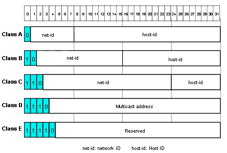
Figure 1-1 Five classes of IP addresses
Here, Class A, Class B and Class C addresses are unicast addresses, while Class D addresses are multicast ones and class E addresses are reserved for special applications in future. The first three types are commonly used.
The IP address is in dotted decimal format. Each IP address contains four integers in dotted decimal notation. Each integer corresponds to one byte, for example, 10.110.50.101.
When using IP addresses, note that some of them are reserved for special uses, and are seldom used. The IP addresses you can use are listed in the following table.
Table 1-1 IP address classes and ranges
|
Network class |
Address range |
Note |
|
A |
0.0.0.0 to 127.255.255.255 |
An all-zero host ID indicates the IP address is a network address, and is used for network routing. An all-one host ID indicates the IP address is a broadcast address, and is used to broadcast packets to all the hosts on the network. The IP address 0.0.0.0 is used for the host that is not put into use after startup. The IP address with the network ID being 0 indicates the current network and its network can be cited by the router without knowing the network number. The IP addresses with the format of 127.X.Y.Z are reserved for self-loop test and the packets sent to these addresses are not output to the line. The packets are processed internally and regarded as input packets. |
|
B |
128.0.0.0 to 191.255.255.255 |
An all-zero host ID indicates that the IP address is a network address, and is used for network routing. An all-one host ID indicates the IP address is a broadcast address, and is used to broadcast packets to all hosts on the network. |
|
C |
192.0.0.0 to 223.255.255.255 |
An all-zero host ID indicates that the IP address is a network address, and is used for network routing. An all-one host ID indicates the IP address is a broadcast address, and is used to broadcast packets to all hosts on the network. |
|
D |
224.0.0.0 to 239.255.255.255 |
Addresses of class D are multicast addresses, among which: l IP address 224.0.0.0 is reserved and will not be allocated. Those from 224.0.0.1 to 224.0.0.255 are reserved for routing protocols and some protocols that are used to discover and maintain simple topologies. l Those from 239.0.0.0 to 239.255.255.255 are used for local multicast management. l Those from 224.0.0.255 to 238.255.255.255 are for users. |
|
E |
240.0.0.0 to 255.255.255.254 |
The addresses are reserved for future use. |
|
Other addresses |
255.255.255.255 |
255.255.255.255 is used as a Local Area Network (LAN) broadcast address. |
With rapid development of the Internet, IPv4 addresses are depleting in a few years. The traditional IP address allocation method wastes IP addresses greatly. In order to make full use of the available IP addresses, the concept of mask and subnet is proposed.
A mask is a 32-bit number corresponding to an IP address. The number consists of contiguous 1s and 0s. In general, a mask is started with consecutive 1s. The mask divides the IP address into two parts: subnet address and host address. The part of an IP address that corresponds to the bits 1s in the mask indicates the subnet address and the other part of IP address indicate the host address. If there is no subnet division, then its subnet mask is the default value and the length of "1" indicates the net-id length. Therefore, for IP addresses of classes A, B and C, the default values of corresponding subnet mask are 255.0.0.0, 255.255.0.0 and 255.255.255.0 respectively.
The mask can be used to divide a Class A network containing more than 16,000,000 hosts or a Class B network containing more than 60,000 hosts into multiple small networks. Each small network is called a subnet. For example, for the Class B network address 138.38.0.0, the mask 255.255.224.0 can be used to divide the network into eight subnets: 138.38.0.0, 138.38.32.0, 138.38.64.0, 138.38.96.0, 138.38.128.0, 138.38.160.0, 138.38.192.0 and 138.38.224.0 (Refer to the following figure). Each subnet can contain more than 8000 hosts. Subnetting enhances flexibility in network construction.
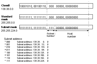
Figure 1-2 Subnet division of an IP address
The following sections describe IP address configuration tasks:
l Associating a Hostname to an IP Address
l Configuring the IP Address of a VLAN Interface
l IP Address Protection Configuration
Using this command, you can associate a host name with an IP address. After that, when using an application like telnet, you can use the host name instead of the IP address that is hard to memorize, and the system automatically translates the host name to the IP address.
Perform the following configuration in system view to associate a hostname with an IP address:
|
To do… |
Use the command… |
|
Associate a hostname with an IP address |
ip host hostname ip-address |
|
Remove the association |
undo ip host hostname [ ip-address ] |
By default, there is no host name associated to any host IP address.
You can configure an IP address for every VLAN interface of the switch. Generally, it is enough to configure one IP address for an interface. You can also configure 21 IP addresses for an interface at most, so that it can be connected to more subnets. Among these IP addresses, one is the primary IP address and all others are secondary.
When configuring an IP address for a VLAN interface, you can specify a handling policy for directed broadcasts destined for the VLAN.
l With the forward keyword specified, the interface will broadcast the received directed packets in the VLAN.
l With the drop keyword specified, the interface will discard the received directed broadcasts.
Perform the following configuration in VLAN interface view to configure/delete an IP address for a VLAN interface:
|
To do… |
Use the command… |
|
Configure an IP address for a VLAN interface |
ip address ip-address { mask | mask-length } [ sub ] [ direct-broadcast { forward | drop } ] |
|
Delete an IP address of a VLAN interface |
undo ip address [ ip-address { mask | mask-length } [ sub ] ] |
& Note:
l If you re-configure an IP address for a VLAN-interface and the new IP address is not in the same network segment as the previous one, the system will display whether to continue. If you do continue, the IP address of the VLAN interface will be modified. In addition, if the ARP entries (including dynamic ARP entries and static ARP entries) in the original network segment match the new network segment, they will not be removed; otherwise, the ARP entries in the original network segment will be removed.
l A policy for handling directed broadcasts, if specified for an IP address of a VLAN interface, will be removed when the IP address is removed from the VLAN interface.
l Super VLAN interfaces cannot forward directed broadcasts. After a super VLAN becomes a common VLAN, its VLAN interface can forward directed broadcasts.
l If a policy for handling directed broadcast is configured for an IP address of a VLAN interface, intermixing is forbidden in the VLAN; otherwise, packet loops may occur.
l Since WAN interfaces currently cannot forward directed broadcasts, it makes no sense to specify a policy for handling directed broadcasts received on WAN interfaces.
By default, no IP address is configured for a VLAN interface.
The IP address protection function stores IP-MAC bindings for legal users to filter illegal users. This function works once configured on the switch, without configurations on the server or client.
The IP address protection function needs to work together with the MAC address auto filling function to record IP-MAC bindings. When the MAC address auto filling function is enabled, you can configure a static ARP entry with only an IP address. The MAC address auto filling function can automatically fill the ARP entry with the learned MAC address.
After the IP address protection function is enabled on a VLAN interface, the interface will no longer dynamically learn ARP entries, and existing dynamic ARP entries will be removed. At the same time, the switch will enable the MAC address auto filling function, and then you can configure static ARP entries that have only IP addresses (auto-fill ARP entries). The switch will automatically fill the MAC address in the ARP entries so that only users matching the static ARP entries can access the network.
The tasks of IP address protection configuration include:
l Configuring an auto-fill ARP entry
l Enabling IP address protection
Follow these steps to configure IP address protection:
|
To do… |
Use the command… |
Remarks |
|
Enter system view |
system-view |
— |
|
Configuring an auto-fill ARP entry |
arp static ip-address |
Optional For detailed information about this command, refer to the arp static command in ARP Commands in the IP Services Volume. |
|
Enter VLAN interface view |
interface vlan-interface vlan-id |
— |
|
Enable IP address protection |
ip-protect enable |
Required By default, the IP address protection function is disabled on a VLAN interface. |
|
View the IP address protection status of the current VLAN interface |
display this |
Available in any view |
![]() Caution:
Caution:
l The MAC address auto filling function is enabled only after the IP address protection function is enabled on the interface.
l Once an auto-fill ARP entry is filled with a MAC address, the entry becomes a normal static ARP entry and cannot be filled again.
|
To do… |
Use the command… |
Remarks |
|
Display all hosts on the network and the corresponding IP addresses |
display ip host |
Available in any view |
|
Display the configuration of a port or all ports |
display ip interface [ brief ] [ interface-type interface-number ] |
Configure the IP address as 129.2.2.1 and subnet mask as 255.255.255.0 for the VLAN interface 1 of the switch.
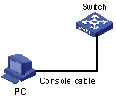
Figure 1-3 Network diagram for IP address configuration
# Enter VLAN interface 1.
<H3C> system-view
System View: return to User View with Ctrl+Z.
[H3C] interface vlan-interface 1
# Configure an IP address for VLAN interface 1.
[H3C-Vlan-interface1] ip address 129.2.2.1 255.255.255.0
Fault 1: The switch cannot ping through a certain host in the LAN.
Troubleshooting can be performed as follows:
1) Check the configuration of the switch. Use the display arp command to view the ARP entry table.
2) Check which VLAN includes the port of the switch used to connect to the host. Verify the VLAN has been configured with a VLAN interface. Verify the IP address of the VLAN interface and that of the host are on the same network segment.
3) If the configuration is correct, enable ARP debugging on the switch, and check whether the switch can correctly send and receive ARP packets. If it can only send ARP packets but cannot receive them, errors may occur on the Ethernet physical layer.
