03-S12500_Attack_Protection_Configuration_Examples
Chapters Download (366.74 KB)
| Title | Size | Download |
|---|---|---|
| 03-S12500_Attack_Protection_Configuration_Examples | 366.74 KB |
Contents
Example: Configuring link layer attack protection
Configuration restrictions and guidelines
Example: Configuring ARP attack protection
Example: Configuring network layer attack protection
Configuration restrictions and guidelines
Example: Configuring transport layer attack protection
This document provides configuration examples of link layer attack protection, ARP attack protection, network layer attack protection, and transport layer attack protection, as defined in Table 1.
Table 1 Attack protection types
|
Attack protection types |
Description |
|
|
Link layer attack protection |
MAC address attack protection |
Prevents the attack of packets with different source MAC addresses or VLANs by configuring the maximum number of MAC addresses that an interface can learn. |
|
STP packet attack protection |
Provides protection measures such as BPDU guard, root guard, loop guard, and TC-BPDU guard. |
|
|
ARP attack protection |
ARP source suppression |
Prevents IP attack packets from fixed sources. |
|
ARP black hole routing |
Prevents IP attack packets from sources that are not fixed. |
|
|
ARP active acknowledgement |
Prevents user spoofing. |
|
|
Source MAC-based ARP attack detection |
Prevents ARP packet attacks from the same source MAC. |
|
|
ARP packet source MAC consistency check |
Prevents attacks from ARP packets whose source MAC address in the Ethernet header is different from the sender MAC address in the message body. |
|
|
Network layer attack protection |
uRPF check |
Protects a network against source spoofing attacks. |
|
TTL attack protection |
Prevents an attack by disabling sending ICMP time exceeded messages. |
|
|
Transport layer attack protection |
SYN flood attack protection |
Enables the server to return a SYN ACK message when it receives a TCP connection request, without establishing a half-open TCP connection. |
The configuration examples in this document were created and verified in a lab environment, and all the devices were started with the factory default configuration. When you are working on a live network, make sure you understand the potential impact of every command on your network.
This document assumes that you have basic knowledge of attack protection.
As shown in Figure 1, Switch A, Switch B, and Switch C run MSTP. Switch B acts as the root bridge, and GigabitEthernet 2/0/1 on Switch C is blocked.
Configure the following features to protect against link layer attacks:
· Configure root guard on GigabitEthernet 2/0/1 and GigabitEthernet 2/0/2 of Switch B for Switch B to act as the root bridge.
· Configure loop guard on GigabitEthernet 2/0/2 of Switch C to prevent temporary loops. The loop guard feature keeps the port in Discarding state in all MSTIs when it receives no BPDU.
· Configure BPDU guard on GigabitEthernet 2/0/3 on Switch A and GigabitEthernet 2/0/3 on Switch C. The BPDU guard feature prevents the ports from performing spanning tree calculations when it receives forged BPDUs with a higher priority.
· Enable TC-BPDU guard on Switch A, Switch B, and Switch C. The TC-BPDU guard feature prevents a large number of TC-BPDUs from affecting the network in a short time.
· Configure the maximum number of MAC addresses that can be learned by ports at the access side of Switch A and Switch C. This configuration protects the devices from a large number of attack packets that have different source MAC addresses. The attack packets might cause a large MAC table and low forwarding performance.
· Configure broadcast and multicast suppressions on all ports on Switch A, Switch B, and Switch C. When incoming broadcast or multicast traffic exceeds the threshold, an interface discards broadcast or multicast packets until the traffic drops below the threshold.

To rapidly transit Switch A's and Switch C's ports that connect to user terminals to the forwarding state, use the stp edged-port command to configure GigabitEthernet 2/0/3 on Switch A and GigabitEthernet 2/0/3 on Switch C as edge ports.
This example was created and verified on S12500-CMW710-R7129.
When you configure link layer attack protection, follow these restrictions and guidelines:
· On a port, the loop guard function is mutually exclusive with the root guard function or the edge port setting.
· Do not configure the loop guard function on a port that connects to user terminals. Otherwise, the port stays in Discarding state in all MSTIs because it cannot receive BPDUs.
# Specify IP addresses for interfaces. (Details not shown.)
# Configure STP BPDU guard.
<SwitchA> system-view
[SwitchA] stp bpdu-protection
[SwitchA] interface GigabitEthernet 2/0/3
[SwitchA-GigabitEthernet2/0/3] undo shutdown
[SwitchA-GigabitEthernet2/0/3] stp edged-port
[SwitchA-GigabitEthernet2/0/3] quit
# Configure TC-BPDU guard.
[SwitchA] stp tc-protection
[SwitchA] stp tc-protection threshold 10
# Configure the maximum number of MAC addresses that a port at the access side can learn (for example, GigabitEthernet 2/0/3).
[SwitchA] interface GigabitEthernet 2/0/3
[SwitchA-GigabitEthernet2/0/3] mac-address max-mac-count 1024
[SwitchA-GigabitEthernet2/0/3] quit
# Set the broadcast and multicast suppression thresholds on all ports that include ports at the access side (for example, GigabitEthernet 2/0/3).
[SwitchA] interface range GigabitEthernet 2/0/1 to GigabitEthernet 2/0/3
[SwitchA-if-range] undo shutdown
[SwitchA-if-range] broadcast-suppression pps 6400
[SwitchA-if-range] multicast-suppression pps 6400
[SwitchA-if-range] quit
# Specify IP addresses for interfaces. (Details not shown.)
# Configure root guard on GigabitEthernet 2/0/2 and GigabitEthernet 2/0/1.
<SwitchB> system-view
[SwitchB] interface GigabitEthernet 2/0/2
[SwitchB-GigabitEthernet2/0/2] undo shutdown
[SwitchB-GigabitEthernet2/0/2] stp root-protection
[SwitchB-GigabitEthernet2/0/2] quit
[SwitchB] interface GigabitEthernet 2/0/1
[SwitchB-GigabitEthernet2/0/1] undo shutdown
[SwitchB-GigabitEthernet2/0/1] stp root-protection
[SwitchB-GigabitEthernet2/0/1] quit
# Configure TC-BPDU guard.
[SwitchB] stp tc-protection
[SwitchB] stp tc-protection threshold 10
# Set the broadcast and multicast suppression thresholds on GigabitEthernet 2/0/1 and GigabitEthernet 2/0/2.
[SwitchB] interface range GigabitEthernet 2/0/1 to GigabitEthernet 2/0/2
[SwitchB-if-range] broadcast-suppression pps 6400
[SwitchB-if-range] multicast-suppression pps 6400
[SwitchB-if-range] quit
# Specify IP addresses for interfaces. (Details not shown.)
# Configure STP BPDU guard.
<SwitchC> system-view
[SwitchC] stp bpdu-protection
[SwitchC] interface GigabitEthernet 2/0/3
[SwitchC-GigabitEthernet2/0/3] undo shutdown
[SwitchC-GigabitEthernet2/0/3] stp edged-port
[SwitchC-GigabitEthernet2/0/3] quit
# Configure root guard on GigabitEthernet 2/0/1.
[SwitchC] interface GigabitEthernet 2/0/1
[SwitchC-GigabitEthernet2/0/1] undo shutdown
[SwitchC-GigabitEthernet2/0/1] stp root-protection
[SwitchC-GigabitEthernet2/0/1] quit
# Configure loop guard on GigabitEthernet 2/0/2.
[SwitchC] interface GigabitEthernet 2/0/2
[SwitchC-GigabitEthernet2/0/2] undo shutdown
[SwitchC-GigabitEthernet2/0/2] stp loop-protection
[SwitchC-GigabitEthernet2/0/2] quit
# Configure TC-BPDU guard.
[SwitchC] stp tc-protection
[SwitchC] stp tc-protection threshold 10
# Configure the maximum number of MAC addresses that a port at the access side can learn (for example, GigabitEthernet 2/0/3).
[SwitchC] interface GigabitEthernet 2/0/3
[SwitchC-GigabitEthernet2/0/3] mac-address max-mac-count 1024
[SwitchC-GigabitEthernet2/0/3] quit
# Set the broadcast and multicast suppression thresholds on all ports that include ports at the access side (for example, GigabitEthernet 2/0/3).
[SwitchC] interface range GigabitEthernet 2/0/1 to GigabitEthernet 2/0/3
[SwitchC-if-range] broadcast-suppression pps 6400
[SwitchC-if-range] multicast-suppression pps 6400
[SwitchC-if-range] quit
Verify the following items:
· After receiving STP BPDUs, the ports GigabitEthernet 2/0/3 of Switch A and Switch C go down. You can bring them up by executing the undo shutdown command.
· After STP BPDUs with higher priority are sent to a port, the root port does not change, and the STP topology is stable.
· After receiving a large number of various TC BPDUs, Switch A, Switch B, and Switch C do not refresh the FIB table frequently, and no serious packet loss occurs.
· After you send a large number of broadcasts to GigabitEthernet 2/0/3 on Switch A and GigabitEthernet 2/0/3 on Switch C, no broadcast flooding occurs on the uplink ports.
· Switch A:
#
stp bpdu-protection
stp tc-protection
stp tc-protection threshold 10
#
interface GigabitEthernet 2/0/1
port link-mode bridge
broadcast-suppression pps 6400
multicast-suppression pps 6400
#
interface GigabitEthernet 2/0/2
port link-mode bridge
broadcast-suppression pps 6400
multicast-suppression pps 6400
#
interface GigabitEthernet 2/0/3
port link-mode bridge
mac-address max-mac-count 1024
stp edged-port
broadcast-suppression pps 6400
multicast-suppression pps 6400
#
· Switch B:
#
stp tc-protection
stp tc-protection threshold 10
#
interface GigabitEthernet 2/0/1
port link-mode bridge
stp root-protection
broadcast-suppression pps 6400
multicast-suppression pps 6400
#
interface GigabitEthernet 2/0/2
port link-mode bridge
stp root-protection
broadcast-suppression pps 6400
multicast-suppression pps 6400
#
interface GigabitEthernet 2/0/3
port link-mode bridge
stp edged-port
#
· Switch C:
#
stp bpdu-protection
stp tc-protection
stp tc-protection threshold 10
#
interface GigabitEthernet 2/0/1
port link-mode bridge
stp root-protection
broadcast-suppression pps 6400
multicast-suppression pps 6400
#
interface GigabitEthernet 2/0/2
port link-mode bridge
stp loop-protection
broadcast-suppression pps 6400
multicast-suppression pps 6400
#
interface GigabitEthernet 2/0/3
port link-mode bridge
mac-address max-mac-count 1024
broadcast-suppression pps 6400
multicast-suppression pps 6400
#
As shown in Figure 2, Switch A and Switch B form a VRRP group.
Configure the ARP attack protection features to protect Switch A and Switch B.
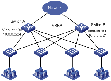
This example was created and verified on S12500-CMW710-R7129.
# Specify IP addresses for interfaces. (Details not shown.)
# Configure ARP source suppression. Set the maximum number of unresolvable packets that can be received in 5 seconds to 8 to prevent IP attack packets from fixed sources.
<SwitchA> system-view
[SwitchA] arp source-suppression enable
[SwitchA] arp source-suppression limit 8
# Configure ARP black hole routing to prevent IP attack packets from sources that are not fixed.
[SwitchA] arp resolving-route enable
# Configure ARP active acknowledgment to prevent user spoofing.
[SwitchA] arp active-ack enable
# Configure source MAC-based ARP attack detection to prevent ARP packet attacks from the same source MAC.
[SwitchA] arp source-mac filter
[SwitchA] arp source-mac threshold 25
# Configure ARP packet source MAC address consistency check to prevent attacks from ARP packets with different source MAC addresses in the Ethernet header and in the message body.
[SwitchA] arp valid-check enable
# Specify IP addresses for interfaces. (Details not shown.)
# Configure ARP source suppression. Set the maximum number of unresolvable packets that can be received in 5 seconds to 8 to prevent IP attack packets from fixed sources.
<SwitchB> system-view
[SwitchB] arp source-suppression enable
[SwitchB] arp source-suppression limit 8
# Configure ARP black hole routing to prevent IP attack packets from sources that are not fixed.
[SwitchB] arp resolving-route enable
# Configure ARP active acknowledgment to prevent user spoofing.
[SwitchB] arp active-ack enable
# Configure source MAC-based ARP attack detection to prevent ARP packet attacks from the same source MAC.
[SwitchB] arp source-mac filter
[SwitchB] arp source-mac threshold 25
# Configure ARP packet source MAC address consistency check to prevent attacks from ARP packets with different source MAC addresses in the Ethernet header and in the message body.
[SwitchB] arp valid-check enable
After you use a PC to send ARP attack packets to a switch:
· No busy CPU event occurs.
· Other service modules are operating correctly.
Take ARP source suppression as an example. After you send 20 forged packets with fixed source IP addresses and unresolvable destination IP addresses to a switch, the switch stops resolving the packets when the number of unresolvable packets within 5 seconds reaches 8.
# Display information about the ARP source suppression configuration.
<Sysname> display arp source-suppression
ARP source suppression is enabled
Current suppression limit: 8
Current cache length: 16
· Switch A:
#
arp source-suppression enable
arp source-suppression limit 8
arp resolving-route enable
arp active-ack enable
arp source-mac filter
arp source-mac threshold 25
arp valid-check enable
#
· Switch B:
#
arp source-suppression enable
arp source-suppression limit 8
arp resolving-route enable
arp active-ack enable
arp source-mac filter
arp source-mac threshold 25
arp valid-check enable
#
As shown in Figure 3, configure the network layer protection features to protect Switch A from being attacked by IP packet attacks from users and the network.
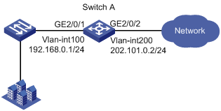
This example was created and verified on S12500-CMW710-R7129.
When you configure network layer attack protection, follow these restrictions and guidelines:
· By default, Ethernet, VLAN, and aggregate interfaces are down. You must use the undo shutdown command to bring them up.
· After you disable sending ICMP time exceeded messages, the traceroute feature is not available.
# Specify IP addresses for interfaces. (Details not shown.)
# Configure uRPF to prevent source spoofing attacks.
[SwitchA] interface vlan-interface 100
[SwitchA-Vlan-interface100] ip urpf strict
[SwitchA-Vlan-interface100] quit
[SwitchA] interface vlan-interface 200
[SwitchA-Vlan-interface200] ip urpf strict
[SwitchA-Vlan-interface200] quit
# Disable sending ICMP time exceeded messages to prevent attacks from packets with TTL 1. Sending ICMP time exceeded messages is disabled by default.
[SwitchA] undo ip ttl-expires enable
1. Enable ICMP debugging by executing the debugging ip icmp command on Switch A. Use a PC to send packets with TTL 1 to Switch A. Switch A does not display any ICMP debugging information, and the PC does not receive TTL timeout ICMP packets.
# Enable sending ICMP time exceeded messages. (Details not shown.)
# Display debugging information. (Switch A forwards the attack packets.)
<System>*Jun 14 14:43:31:068 2013 NM-3 SOCKET/7/ICMP: -MDC=1-Slot=2;
Time(s):1371221011 ICMP Output:
ICMP Packet: src = 6.0.0.1, dst = 202.101.0.2
type = 11, code = 0 (ttl-exceeded)
Original IP: src = 202.101.0.2, dst = 192.168.0.2
proto = 253, first 8 bytes = 00000000 00000000
2. After you use a PC to send packets with forged source IP addresses to Switch A, the packets are filtered.
# Display uRPF configuration on VLAN-interface 100 and VLAN-interface 200.
<Sysname>display ip urpf interface Vlan-interface 100
uRPF configuration information of interface Vlan-interface100:
Check type: strict
Allow default route
<Sysname>display ip urpf interface Vlan-interface 200
uRPF configuration information of interface Vlan-interface200:
Check type: strict
Allow default route
#
vlan 100
#
vlan 200
#
interface Vlan-interface100
ip address 192.168.0.1 255.255.255.0
#
interface Vlan-interface200
ip address 202.101.0.2 255.255.255.0
#
interface GigabitEthernet2/0/1
port access vlan 100
#
interface GigabitEthernet2/0/2
port access vlan 200
#
interface Vlan-interface100
ip address 192.168.0.1 255.255.255.0
ip urpf strict
#
As shown in Figure 4, configure SYN Cookie protection on Switch A to protect Switch A from SYN Flood attacks and to make sure BGP can operate correctly.
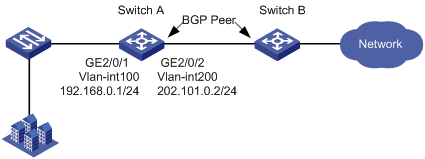
This example was created and verified on S12500-CMW710-R7129.
# Specify IP addresses for interfaces. (Details not shown.)
# Enable SYN Cookie.
<SwitchA> system-view
[SwitchA] tcp syn-cookie enable
When you send to Switch A a large number of protocol packets that have the destination port specified as the BGP protocol port (TCP port 179), BGP operates correctly.
#
tcp syn-cookie enable
#
· H3C S12500 Routing Switch Series Layer 2—LAN Switching Configuration Guide
· H3C S12500 Routing Switch Series Layer 2—LAN Switching Command Reference
· H3C S12500 Routing Switch Series Layer 3—IP Services Configuration Guide
· H3C S12500 Routing Switch Series Layer 3—IP Services Command Reference
· H3C S12500 Routing Switch Series Security Configuration Guide
· H3C S12500 Routing Switch Series Security Command Reference
