This document provides BFD configuration
examples.
Bidirectional forwarding detection (BFD)
provides a general-purpose, standard, medium- and protocol-independent fast
failure detection mechanism. It can detect connectivity failures quickly in an
IP network.
BFD provides the following session modes:
· Echo packet mode—The
local end of the link sends echo packets to establish BFD sessions and monitor
link status. The peer end does not establish BFD sessions and only forwards the
packets back to the originating end.
· Control packet mode—Both
ends of the link exchange BFD control packets to monitor link status.
Table 1 BFD operating modes for supported protocols
|
Protocol
|
Session mode
|
Single-hop or multi-hop detection
|
|
VRRP
|
Echo packet mode
|
Single-hop
|
|
OSPF
|
Echo packet mode or control packet mode
|
Single-hop
|
|
IS-IS
|
Control packet mode
|
Single-hop
|
|
RIP
|
Echo packet mode
|
Single-hop
|
|
BGP
|
Control packet mode
|
Single-hop/Multi-hop
|
|
Static routing
|
Echo packet mode or control packet mode
|
Single-hop
|
The configuration examples in this document
were created and verified in a lab environment, and all the devices were started
with the factory default configuration. When you are working on a live network,
make sure you understand the potential impact of every command on your network.
This document assumes that you have basic
knowledge of H3C BFD.
General configuration restrictions
and guidelines
IP tunnels do not support BFD, for example,
IPv6 over IPv4 tunnels.
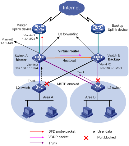
As shown in Figure 1:
· Assign the departments to different areas, and
use a layer 2 switch to connect devices of each department to the core switches
(Switch A and Switch B).
· Create a VRRP group on the core switches, and
configure Switch A as the master and Switch B as the backup.
· Configure BFD on the backup to monitor the
status of the master. When the master fails, the backup takes over.
Figure 1 Network diagram

This configuration example was created
and verified on S12500-CMW710-R7129.
# Assign an IP
address to the VLAN interface.
<SwitchA> system-view
[SwitchA] vlan 2
[SwitchA–vlan2] port
GigabitEthernet 3/0/1
[SwitchA–vlan2] quit
[SwitchA] interface GigabitEthernet 3/0/1
[SwitchA-GigabitEthernet3/0/1] undo
shutdown
[SwitchA-GigabitEthernet3/0/1] quit
[SwitchA] interface vlan-interface 2
[SwitchA–Vlan-interface2] undo
shutdown
[SwitchA–Vlan-interface2] ip
address 192.168.0.101 24
# Create VRRP group 1, and configure the
virtual IP address 192.168.0.10 for the group.
[SwitchA–Vlan-interface2] vrrp
vrid 1 virtual-ip 192.168.0.10
# Set the priority
of Switch A in VRRP group 1 to 110. This priority is higher than Switch B's
priority. It makes sure Switch A can be elected as the master.
[SwitchA–Vlan-interface2] vrrp
vrid 1 priority 110
[SwitchA–Vlan-interface2] quit
# Assign an IP
address to the VLAN interface.
<SwitchB> system-view
[SwitchB] vlan 2
[SwitchB–vlan2] port
GigabitEthernet 3/0/1
[SwitchB–vlan2] quit
[SwitchB] interface GigabitEthernet 3/0/1
[SwitchB-GigabitEthernet3/0/1] undo
shutdown
[SwitchB-GigabitEthernet3/0/1] quit
[SwitchB] interface vlan-interface 2
[SwitchB–Vlan-interface2] undo
shutdown
[SwitchB–Vlan-interface2] ip
address 192.168.0.102 24
# Create VRRP group 1, and configure the
virtual IP address 192.168.0.10 for the group.
[SwitchB–Vlan-interface2] vrrp
vrid 1 virtual-ip 192.168.0.10
[SwitchB–Vlan-interface2] quit
# Configure the source IP address of BFD
echo packets. The source IP address cannot be on the same network segment as
any local interface's IP address.
[SwitchB] bfd echo-source-ip
10.10.10.10
# Configure the minimum interval for
receiving BFD echo packets.
[SwitchB] interface vlan-interface 2
[SwitchB–Vlan-interface2] bfd min-echo-receive-interval
10
# Configure the single-hop detection time
multiplier.
[SwitchB–Vlan-interface2] bfd
detect-multiplier 3
[SwitchB–Vlan-interface2] quit
# Create a track object.
[SwitchB] track 1 bfd echo interface
vlan-interface 2 remote ip 192.168.0.101 local ip 192.168.0.102
# Associate VRRP group 1 with track entry
1. When the status of the track entry becomes Negative,
Switch B becomes the master.
[SwitchB] interface vlan-interface 2
[SwitchB–Vlan-interface2] vrrp
vrid 1 track 1 switchover
[SwitchB–Vlan-interface2] quit
# Display detailed information about VRRP
group 1 on Switch A.
[SwitchA] display vrrp verbose
IPv4 Virtual
Router Information:
Running Mode : Standard
Total number of virtual routers : 1
Interface Vlan-interface2
VRID :
1 Adver Timer : 100
Admin Status :
Up State : Master
Config Pri :
110 Running Pri : 110
Preempt Mode :
Yes Delay Time : 0
Auth Type : None
Virtual IP : 192.168.0.10
Virtual MAC : 0000-5e00-0101
Master IP : 192.168.0.101
The output shows that Switch A is the
master.
# Display detailed information about VRRP
group 1 on Switch B.
[SwitchB] display vrrp verbose
IPv4 Virtual
Router Information:
Running Mode : Standard
Total number of virtual routers : 1
Interface Vlan-interface2
VRID :
1 Adver Timer : 100
Admin Status :
Up State : Backup
Config Pri :
100 Running Pri : 100
Preempt Mode : Yes
Delay Time : 0
Auth Type : None
Virtual IP : 192.168.0.10
Master IP : 192.168.0.101
VRRP Track Information:
Track Object :
1 State : Positive Switchover
The output shows that Switch B is the
backup.
# Display BFD session information on Switch
B.
[SwitchB]
display bfd session
Total Session Num: 1 Up Session Num: 1 Init
Mode: Active
IPv4 Session Working Under Echo Mode:
LD
SourceAddr DestAddr State Holdtime
Interface
1 192.168.0.102 192.168.0.101
Up 30ms Vlan2
The output shows that the BFD session is created
and is up.
# When Switch A is down, use the display vrrp
command to display the state information about the VRRP group.
[SwitchB] display vrrp verbose
IPv4 Virtual
Router Information:
Running Mode : Standard
Total number of virtual routers : 1
Interface Vlan-interface2
VRID :
1 Adver Timer : 100
Admin Status :
Up State : Master
Config Pri :
100 Running Pri : 100
Preempt Mode :
Yes Delay Time : 0
Auth Type : None
Virtual IP : 192.168.1.10
Virtual MAC : 0000-5e00-0101
Master IP : 192.168.1.102
VRRP Track Information:
Track Object :
1 State : Negative Switchover
The output shows that Switch B becomes the
master.
# Display BFD session information on Switch
B.
[SwitchB] display bfd session
Total Session Num: 1 Up Session Num: 0 Init Mode: Active
IPv4 Session
Working Under Echo Mode:
LD SourceAddr
DestAddr State Holdtime Interface
1 192.168.0.102 192.168.0.101
Down / Vlan2
The output shows that the BFD session state
is down.
# Display detailed information about the
track object on Switch B.
[SwitchB] display track 1
Track ID: 1
State: Negative
Duration: 0 days 0 hours 2 minutes 6 seconds
Notification
delay: Positive 0, Negative 0 (in seconds)
Tracked object:
BFD session
mode: Echo
Outgoing interface: Vlan-interface2
VPN instance name: -
Remote IP :
192.168.0.101
Local IP : 192.168.0.102
The output shows that the track entry
status is Negative.
· Switch A:
#
vlan 2
#
interface Vlan-interface2
ip address 192.168.0.101
255.255.255.0
vrrp vrid 1 virtual-ip
192.168.0.10
vrrp vrid 1 priority 110
#
interface GigabitEthernet3/0/1
port link-mode bridge
port access vlan 2
#
· Switch B:
#
vlan 2
#
bfd echo-source-ip
10.10.10.10
#
interface Vlan-interface2
ip address 192.168.0.102
255.255.255.0
vrrp vrid 1 virtual-ip
192.168.0.10
vrrp vrid 1 track 1
switchover
bfd min-echo-receive-interval
10
bfd detect-multiplier 3
#
interface GigabitEthernet3/0/1
port link-mode bridge
port access vlan 2
#
track 1 bfd echo interface
Vlan-interface2 remote ip 192.168.0.101 local ip 192.168.0.102
#
As shown in Figure 2:
· Assign the departments to different areas, and
use a layer 2 switch to connect devices of each department to the core switches
(Switch A and Switch B).
· Create a VRRP group on the core switches, and
configure Switch A as the master and Switch B as the backup.
· Configure BFD on the master to monitor the
status of the uplink. When the uplink is down, the backup takes over.
Figure 2 Network diagram
This configuration example was created and
verified on S12500-CMW710-R7129.
# Configure the uplink
VLAN interface and its IP address.
<SwitchA> system-view
[SwitchA] vlan 3
[SwitchA–vlan3] port GigabitEthernet
3/0/1
[SwitchA–vlan3] quit
[SwitchA] interface GigabitEthernet
3/0/1
[SwitchA-GigabitEthernet3/0/1] undo
shutdown
[SwitchA-GigabitEthernet3/0/1] quit
[SwitchA] interface vlan-interface 3
[SwitchA–Vlan-interface3] undo
shutdown
[SwitchA–Vlan-interface3] ip
address 1.1.1.1 24
[SwitchA–Vlan-interface3] quit
# Configure the VLAN interface to be enabled
with VRRP and its IP address.
[SwitchA] vlan 2
[SwitchA–vlan2] port
GigabitEthernet 3/0/2
[SwitchA–vlan2] quit
[SwitchA] interface GigabitEthernet
3/0/2
[SwitchA-GigabitEthernet3/0/2] undo
shutdown
[SwitchA-GigabitEthernet3/0/2] quit
[SwitchA] interface vlan-interface 2
[SwitchA–Vlan-interface2] undo
shutdown
[SwitchA–Vlan-interface2] ip
address 192.168.0.101 24
# Create VRRP group 1, and configure the
virtual IP address 192.168.0.10 for the group.
[SwitchA–Vlan-interface2] vrrp
vrid 1 virtual-ip 192.168.0.10
# Set the priority
of Switch A in VRRP group 1 to 110. This priority is higher than Switch B's
priority. It makes sure Switch A can be elected as the master.
[SwitchA–Vlan-interface2]
vrrp vrid 1 priority 110
[SwitchA–Vlan-interface2] quit
# Configure the source IP address of BFD
echo packets. The source IP address cannot be on the same network segment as
any local interface's IP address.
[SwitchA] bfd echo-source-ip
10.10.10.10
# Configure the minimum interval for
receiving BFD echo packets.
[SwitchA] interface vlan-interface 3
[SwitchA–Vlan-interface3] bfd min-echo-receive-interval
10
# Configure the single-hop detection time
multiplier.
[SwitchA–Vlan-interface3] bfd
detect-multiplier 3
[SwitchA–Vlan-interface3] quit
# Create track entry 1 to be associated
with the BFD session to check whether the uplink device with the IP address
1.1.1.2 is reachable.
[SwitchA] track 1 bfd echo interface
vlan-interface 3 remote ip 1.1.1.2 local ip 1.1.1.1
# Associate VRRP
group 1 with track entry 1. When the status of the
track entry becomes Negative, the priority of Switch A decreases by 20.
[SwitchA] interface vlan-interface 2
[SwitchA–Vlan-interface2] vrrp
vrid 1 track 1 reduced 20
[SwitchA–Vlan-interface2] quit
# Configure the VLAN interface to be
enabled with VRRP and its IP address.
<SwitchB> system-view
[SwitchB] vlan 2
[SwitchB–vlan2] port
GigabitEthernet 3/0/1
[SwitchB–vlan2] quit
[SwitchB] interface GigabitEthernet
3/0/1
[SwitchB-GigabitEthernet3/0/1] undo
shutdown
[SwitchB-GigabitEthernet3/0/1] quit
[SwitchB] interface vlan-interface 2
[SwitchB–Vlan-interface2] undo
shutdown
[SwitchB–Vlan-interface2] ip
address 192.168.0.102 24
# Create VRRP group 1, and configure the
virtual IP address 192.168.0.10 for the group.
[SwitchB–Vlan-interface2] vrrp
vrid 1 virtual-ip 192.168.0.10
[SwitchB–Vlan-interface2] quit
# Display detailed information about VRRP
group 1 on Switch A.
[SwitchA] display vrrp verbose
IPv4 Virtual
Router Information:
Running Mode : Standard
Run Method : Virtual MAC
Total number of virtual routers : 1
Interface Vlan-interface2
VRID :
1 Adver Timer : 100
Admin Status :
Up State : Master
Config Pri :
110 Running Pri : 110
Preempt Mode : Yes
Delay Time : 0
Auth Type : None
Virtual IP : 192.168.0.10
Virtual MAC : 0000-5e00-0101
Master IP : 192.168.0.101
VRRP Track Information:
Track Object :
1 State : Positive Pri Reduced : 20
The output shows that Switch A is the
master.
# Display detailed information about VRRP
group 1 on Switch B.
[SwitchB] display vrrp verbose
IPv4 Virtual
Router Information:
Running
Mode : Standard
Total number of virtual routers : 1
Interface Vlan-interface2
VRID :
1 Adver Timer : 100
Admin Status :
Up State : Backup
Config Pri : 100 Running
Pri : 100
Preempt Mode :
Yes Delay Time : 0
Auth Type : None
Virtual IP : 192.168.0.10
Master IP : 192.168.0.101
The output shows that Switch B is the
backup.
# Display BFD session information.
[SwitchA] display bfd session
Total Session Num: 1 Up Session Num: 1 Init Mode: Active
IPv4 Session
Working Under Echo Mode:
LD SourceAddr
DestAddr State Holdtime Interface
1 1.1.1.1 1.1.1.2
Up 30ms Vlan3
The output shows that the BFD session is created
and is up.
# When the uplink
monitored by Switch A is down, use the display vrrp command to display the
state information about the VRRP group. When the uplink monitored by Switch A
is down, display detailed VRRP group information on Switch A.
[SwitchA] display vrrp verbose
IPv4 Virtual
Router Information:
Running
Mode : Standard
Total number of virtual routers : 1
Interface Vlan-interface2
VRID :
1 Adver Timer : 100
Admin Status :
Up State : Backup
Config Pri :
110 Running Pri : 90
Preempt Mode :
Yes Delay Time : 0
Auth Type : None
Virtual IP : 192.168.0.10
Master IP : 192.168.0.102
VRRP Track Information:
Track Object :
1 State : Negative Pri Reduced : 20
# When the uplink
monitored by Switch A is down, display detailed VRRP group information on Switch
B.
[SwitchB] display vrrp verbose
IPv4 Virtual
Router Information:
Running Mode : Standard
Total number of virtual routers : 1
Interface Vlan-interface2
VRID :
1 Adver Timer : 100
Admin Status :
Up State : Master
Config Pri :
100 Running Pri : 100
Preempt Mode :
Yes Delay Time : 0
Auth Type : None
Virtual IP : 192.168.0.10
Virtual MAC : 0000-5e00-0101
Master IP : 192.168.0.102
The output shows that Switch B is the
master.
# Display BFD session information.
[SwitchA] display bfd session
Total Session Num: 1 Up Session Num: 0 Init Mode: Active
IPv4 Session
Working Under Echo Mode:
LD SourceAddr
DestAddr State Holdtime Interface
1 1.1.1.1 1.1.1.2
Down / Vlan3
The output shows that the BFD session state
is down.
# Display detailed information about the
track object on Switch A.
[SwitchA] display track 1
Track ID: 1
State: Negative
Duration: 0
days 0 hours 1 minutes 49 seconds
Notification
delay: Positive 0, Negative 0 (in seconds)
Tracked object:
BFD session
mode: Echo
Outgoing interface: Vlan-interface3
VPN instance name: -
Remote IP
: 1.1.1.2
Local IP
: 1.1.1.1
The output shows that the track entry
status is Negative.
· Switch A:
#
vlan 2
#
vlan 3
#
bfd echo-source-ip
10.10.10.10
#
interface Vlan-interface2
ip address 192.168.0.101
255.255.255.0
vrrp vrid 1 virtual-ip
192.168.0.10
vrrp vrid 1 priority 110
vrrp vrid 1 track 1 reduced
20
#
interface Vlan-interface3
ip address 1.1.1.1
255.255.255.0
bfd min-echo-receive-interval
10
bfd detect-multiplier 3
#
interface GigabitEthernet3/0/1
port link-mode bridge
port access vlan 3
#
interface GigabitEthernet3/0/2
port link-mode bridge
port access vlan 2
#
track 1 bfd echo interface
Vlan-interface3 remote ip 1.1.1.2 local ip 1.1.1.1
#
· Switch B:
#
vlan 2
#
interface Vlan-interface2
ip address 192.168.0.102
255.255.255.0
vrrp vrid 1 virtual-ip
192.168.0.10
#
interface GigabitEthernet3/0/1
port link-mode bridge
port access vlan 2
#
Enable BFD control packet mode on Switch A
and Switch B to help OSPF detect the link failure quickly.
Figure 3 Network diagram

This configuration example was created and
verified on S12500-CMW710-R7129.
In BFD control packet mode, at least one
end must operate in active mode for a BFD session to be established.
# Create a VLAN interface and configure its
IP address.
<SwitchA> system-view
[SwitchA] vlan 10
[SwitchA-vlan10] port GigabitEthernet
3/0/1
[SwitchA-vlan10] quit
[SwitchA] interface GigabitEthernet
3/0/1
[SwitchA-GigabitEthernet3/0/1] undo
shutdown
[SwitchA-GigabitEthernet3/0/1] quit
[SwitchA] interface vlan-interface 10
[SwitchA–Vlan-interface10] undo
shutdown
[SwitchA-Vlan-interface10] ip address
10.1.0.102 24
[SwitchA-Vlan-interface10] quit
# Configure OSPF basic functions and enable
BFD for OSPF.
[SwitchA] ospf
[SwitchA-ospf-1] area 0
[SwitchA-ospf-1-area-0.0.0.0] network
10.1.0.0 0.0.0.255
[SwitchA-ospf-1-area-0.0.0.0] quit
[SwitchA-ospf-1] quit
[SwitchA] interface vlan-interface 10
[SwitchA-Vlan-interface10] ospf bfd
enable
[SwitchA-Vlan-interface10] quit
# Specify the mode for establishing a BFD
session.
[SwitchA] bfd session init-mode active
# Configure the minimum interval for
transmitting single-hop BFD control packets.
[SwitchA] interface vlan-interface 10
[SwitchA-Vlan-interface10] bfd
min-transmit-interval 100
# Configure the minimum interval for
receiving single-hop BFD control packets.
[SwitchA-Vlan-interface10] bfd
min-receive-interval 100
# Configure the single-hop detection time
multiplier.
[SwitchA-Vlan-interface10] bfd
detect-multiplier 3
[SwitchA-Vlan-interface10] quit
# Create a VLAN interface and configure its
IP address.
<SwitchB> system-view
[SwitchB] vlan 10
[SwitchB-vlan10] port GigabitEthernet
3/0/2
[SwitchB-vlan10] quit
[SwitchB] interface GigabitEthernet
3/0/2
[SwitchB-GigabitEthernet3/0/2] undo
shutdown
[SwitchB-GigabitEthernet3/0/2] quit
[SwitchB] interface vlan-interface 10
[SwitchB–Vlan-interface10] undo
shutdown
[SwitchB-Vlan-interface10] ip address
10.1.0.100 24
[SwitchB-Vlan-interface10] quit
# Configure OSPF basic functions and enable
BFD for OSPF.
[SwitchB] ospf
[SwitchB-ospf-1] area 0
[SwitchB-ospf-1-area-0.0.0.0] network
10.1.0.0 0.0.0.255
[SwitchB-ospf-1-area-0.0.0.0] quit
[SwitchB-ospf-1] quit
[SwitchB] interface vlan-interface 10
[SwitchB-Vlan-interface10] ospf bfd
enable
[SwitchB-Vlan-interface10] quit
# Specify the mode for establishing a BFD
session.
[SwitchB] bfd session init-mode
active
# Configure the minimum interval for
transmitting single-hop BFD control packets.
[SwitchB] interface vlan 10
[SwitchB-Vlan-interface10] bfd
min-transmit-interval 100
# Configure the minimum interval for
receiving single-hop BFD control packets.
[SwitchB-Vlan-interface10] bfd
min-receive-interval 100
# Configure the single-hop detection time
multiplier.
[SwitchB-Vlan-interface10] bfd
detect-multiplier 3
[SwitchB-Vlan-interface10] quit
# Display information about OSPF neighbors.
[SwitchA]display ospf peer verbose
OSPF Process 1 with Router
ID 2.2.2.2
Neighbors
Area 0.0.0.0 interface
10.1.0.102(Vlan-interface10)'s neighbors
Router ID: 1.1.1.1 Address:
10.1.0.100 GR State: Normal
State: Full Mode:
Nbr is Slave Priority: 1
DR: 10.1.0.102 BDR: 10.1.0.100
MTU: 0
Options is 0x42 (-|O|-|-|-|-|E|-)
Dead timer due in 32 sec
Neighbor is up for 00:21:37
Authentication Sequence: [ 0 ]
Neighbor state change count: 5
Last Neighbor Down Event:
Router ID: 1.1.1.1
Local Address: 10.1.0.102
Remote Address: 10.1.0.100
Time: Jan 7 10:04:26 2009
Reason: DeadInterval timer expired
The output shows that the two switches have
established an OSPF neighborship.
# Display BFD session information.
[SwitchA] display bfd session verbose
Total Session Num: 1 Up Session Num: 1 Init Mode: Active
IPv4 Session
Working Under Ctrl Mode:
Local Discr:
10 Remote Discr: 1
Source IP:
10.1.0.102 Destination IP: 10.1.0.100
Session State: Up Interface: Vlan-interface10
Min Tx Inter:
100ms Act Tx Inter: 100ms
Min Rx Inter: 100ms Detect Inter: 300ms
Rx Count: 3740 Auth mode: None
Connect Type:
Direct Chassis/Slot: 0
Hold Time: 271ms
Detect Mode: Async
Protocol:
OSPF
Diag Info: No Diagnostic
[SwitchB]
display bfd session verbose
Total Session Num: 1 Up Session Num: 1 Init Mode:
Active
IPv4 Session Working Under Ctrl Mode:
Local Discr: 1 Remote Discr: 10
Source IP: 10.1.0.100 Destination IP:10.1.0.102
Session State: Up Interface: Vlan-interface10
Min Tx
Inter: 100ms Act Tx Inter: 100ms
Min Rx
Inter: 100ms Detect Inter: 300ms
Rx
Count: 3915 Tx Count: 3964
Connect
Type: Direct Running Up for: 00:06:58
Hold
Time: 241ms Auth mode: None
Detect
Mode: Async Chassis/Slot: 1/0
Protocol: OSPF
Diag
Info: No Diagnostic
The output shows that a BFD session is
created and is up.
# When the link between Switch B and the
Layer 2 switch fails, view BFD log information.
%Jan 7 10:39:47:701 2009 125/6697
BFD/4/LOG:Sess[10.1.0.102/10.1.0.100,Vlan10,Ctrl], Sta: UP->DOWN, Diag: 5
%Jan 7 10:39:47:821 2009 125/6697
RM/3/RMLOG:OSPF-NBRCHANGE: Process 1, Neighbor 10.1.0.100(Vlan-interface10)
from Full to Down
The output shows that BFD can quickly
detect the failure and notify OSPF of the failure.
# Execute the display ospf peer verbose command.
[SwitchA] display ospf peer verbose
OSPF Process 1 with Router
ID 2.2.2.2
Last Neighbor Down Event:
Router ID: 1.1.1.1
Local Address: 10.1.0.102
Remote Address: 10.1.0.100
Time: Jan 7 10:39:47 2009
Reason: BFD session down
The output shows that the OSPF neighbor
state changes to down.
· Switch A:
#
vlan 10
#
interface Vlan-interface10
ip address 10.1.0.102
255.255.255.0
ospf bfd enable
bfd min-transmit-interval 100
bfd min-receive-interval 100
bfd detect-multiplier 3
#
interface GigabitEthernet3/0/1
port link-mode bridge
port access vlan 10
#
ospf 1
area 0.0.0.0
network 10.1.0.0 0.0.0.255
#
· Switch B:
#
vlan 10
#
interface Vlan-interface10
ip address 10.1.0.100
255.255.255.0
ospf bfd enable
bfd min-transmit-interval 100
bfd min-receive-interval 100
bfd detect-multiplier 3
#
interface GigabitEthernet3/0/2
port link-mode bridge
port access vlan 10
#
ospf 1
area 0.0.0.0
network 10.1.0.0 0.0.0.255
#
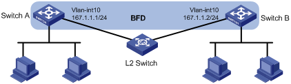
Enable BFD control packet mode on Switch A
and Switch B to help IS-IS detect the link failure quickly.
Figure 4 Network diagram
This configuration example was created and
verified on S12500-CMW710-R7129.
In BFD control packet mode, at least one
end must operate in active mode for a BFD session to be established.
# Create a VLAN interface and configure its
IP address.
<SwitchA> system-view
[SwitchA] vlan 10
[SwitchA-vlan10] port GigabitEthernet
3/0/1
[SwitchA-vlan10] quit
[SwitchA] interface GigabitEthernet
3/0/1
[SwitchA-GigabitEthernet3/0/1] undo
shutdown
[SwitchA-GigabitEthernet3/0/1] quit
[SwitchA] interface vlan-interface 10
[SwitchA–Vlan-interface10] undo
shutdown
[SwitchA-Vlan-interface10] ip address
167.1.1.1 24
[SwitchA-Vlan-interface10] quit
# Configure IS-IS basic functions and
enable BFD for IS-IS.
[SwitchA] isis
[SwitchA-isis-1] network-entity 00.0000.0000.0000.0001.00
[SwitchA-isis-1] quit
[SwitchA] interface vlan-interface 10
[SwitchA-Vlan-interface10] isis
enable
[SwitchA-Vlan-interface10] isis bfd
enable
[SwitchA-Vlan-interface10] quit
# Specify the mode for establishing a BFD
session.
[SwitchA] bfd session init-mode
active
# Configure the minimum interval for
transmitting single-hop BFD control packets.
[SwitchA] interface vlan-interface 10
[SwitchA-Vlan-interface10] bfd
min-transmit-interval 100
# Configure the minimum interval for
receiving single-hop BFD control packets.
[SwitchA-Vlan-interface10] bfd
min-receive-interval 100
# Configure the single-hop detection time
multiplier.
[SwitchA-Vlan-interface10] bfd
detect-multiplier 3
[SwitchA-Vlan-interface10] quit
# Create a VLAN interface and configure its
IP address.
<SwitchB> system-view
[SwitchB] vlan 10
[SwitchB-vlan10] port GigabitEthernet
3/0/2
[SwitchB-vlan10] quit
[SwitchB] interface GigabitEthernet
3/0/2
[SwitchB-GigabitEthernet3/0/2] undo
shutdown
[SwitchB-GigabitEthernet3/0/2] quit
[SwitchB] interface vlan-interface 10
[SwitchB–Vlan-interface10] undo
shutdown
[SwitchB-Vlan-interface10] ip address
167.1.1.2 24
[SwitchB-Vlan-interface10] quit
# Configure IS-IS basic functions and
enable BFD for IS-IS.
[SwitchB] isis
[SwitchB-isis-1] network-entity 00.0000.0000.0000.0002.00
[SwitchB-isis-1] quit
[SwitchB] interface vlan-interface 10
[SwitchB-Vlan-interface10] isis
enable
[SwitchB-Vlan-interface10] isis bfd
enable
[SwitchB-Vlan-interface10] quit
# Specify the mode for establishing a BFD
session.
[SwitchB] bfd session init-mode
active
# Configure the minimum interval for
transmitting single-hop BFD control packets.
[SwitchB] interface vlan-interface 10
[SwitchB-Vlan-interface10] bfd
min-transmit-interval 100
# Configure the minimum interval for
receiving single-hop BFD control packets.
[SwitchB-Vlan-interface10] bfd
min-receive-interval 100
# Configure the single-hop detection time
multiplier.
[SwitchB-Vlan-interface10] bfd
detect-multiplier 3
[SwitchB-Vlan-interface10] quit
# Display information about IS-IS neighbors.
[SwitchA] display isis peer verbose
Peer
information for ISIS(1)
----------------------------
System Id: 0000.0000.0002
Interface: Vlan10
Circuit Id: 0000.0000.0001.01
State: Up
HoldTime: 29s Type: L1(L1L2) PRI: 64
Area Address(es):00.0000
Peer IP Address(es): 167.1.1.2
Uptime: 00:21:20
Adj Protocol: IPv4
System Id: 0000.0000.0002
Interface: Vlan10
Circuit Id: 0000.0000.0001.01
State: Up
HoldTime: 30s Type: L2(L1L2) PRI: 64
Area Address(es):00.0000
Peer IP Address(es): 167.1.1.2
Uptime: 00:21:16
Adj Protocol: IPv4
The output shows that two switches have
established an IS-IS neighborship.
# Display BFD session information.
[SwitchA] display bfd session verbose
Total Session
Num: 1 Up Session Num: 1 Init Mode: Active
IPv4 Session
Working Under Ctrl Mode:
Local
Discr: 11 Remote Discr: 2
Source
IP: 167.1.1.1 Destination IP: 167.1.1.2
Session State: Up Interface: Vlan-interface10
Min Tx
Inter: 100ms Act Tx Inter: 100ms
Min Rx
Inter: 100ms Detect Inter: 300ms
Rx
Count: 718 Tx Count: 674
Connect
Type: Direct Running Up for: 00:01:36
Hold
Time: 220ms Auth mode: None
Detect
Mode: Async Chassis/Slot: 1/0
Protocol: ISIS_BR_L1/ISIS_BR_L2
Diag
Info: No Diagnostic
[SwitchB] display bfd session verbose
Total Session
Num: 1 Up Session Num: 1 Init Mode: Active
IPv4 Session
Working Under Ctrl Mode:
Local
Discr: 2 Remote Discr: 11
Source
IP: 167.1.1.2 Destination IP: 167.1.1.1
Session State: Up Interface: Vlan-interface10
Min Tx
Inter: 100ms Act Tx Inter: 100ms
Min Rx
Inter: 100ms Detect Inter: 300ms
Rx
Count: 860 Tx Count: 910
Connect
Type: Direct Running Up for: 00:01:54
Hold
Time: 262ms Auth mode: None
Detect
Mode: Async Chassis/Slot: 1/0
Protocol: ISIS_BR_L1/ISIS_BR_L2
Diag
Info: No Diagnostic
The output shows that a BFD session is
created and is up.
# When the link between Switch B and the
Layer 2 switch fails, view BFD log information.
%Jan 7 11:25:17:651 2009 125/6697
BFD/4/LOG:Sess[167.1.1.1/167.1.1.2,Vlan10,Ctrl], Sta: UP->DOWN, Diag: 5
%Jan 7 11:25:17:771 2009 125/6697
ISIS/4/ADJLOG:ISIS-1-ADJCHANGE: Adjacency To 0000.0000.0002 (Vlan10) DOWN,
Level-1 Adjacency clea
r.
%Jan 7 11:25:17:921 2009 125/6697
ISIS/4/ADJLOG:ISIS-1-ADJCHANGE: Adjacency To 0000.0000.0002 (Vlan10) DOWN,
Level-2 Adjacency clea
r.
The output shows that BFD can quickly
detect the failure and notify IS-IS of the failure.
· Switch A:
#
vlan 10
#
isis 1
network-entity
00.0000.0000.0000.0001.00
#
interface Vlan-interface10
ip address 167.1.1.1 255.255.255.0
isis enable 1
isis bfd enable
bfd min-transmit-interval 100
bfd min-receive-interval 100
bfd detect-multiplier 3
#
interface GigabitEthernet3/0/1
port link-mode bridge
port access vlan 10
#
· Switch B:
#
vlan 10
#
isis 1
network-entity
00.0000.0000.0000.0002.00
#
interface Vlan-interface10
ip address 167.1.1.2 255.255.255.0
isis enable 1
isis bfd enable
bfd min-transmit-interval 100
bfd min-receive-interval 100
bfd detect-multiplier 3
#
interface GigabitEthernet3/0/2
port link-mode bridge
port access vlan 10
#
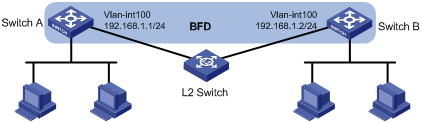
Enable BFD echo packet mode on Switch A to
help OSPF detect the link failure quickly.
Figure 5 Network diagram
This configuration example was created and
verified on S12500-CMW710-R7129.
# Create a VLAN interface and configure its
IP address.
<SwitchA> system-view
[SwitchA] vlan 100
[SwitchA-vlan100] port GigabitEthernet
3/0/1
[SwitchA-vlan100] quit
[SwitchA] interface GigabitEthernet
3/0/1
[SwitchA-GigabitEthernet3/0/1] undo
shutdown
[SwitchA-GigabitEthernet3/0/1] quit
[SwitchA] interface vlan-interface 100
[SwitchA–Vlan-interface100]
undo shutdown
[SwitchA-Vlan-interface100] ip address
198.168.1.1 24
[SwitchA-Vlan-interface100] quit
# Configure RIP basic functions and enable
BFD for RIP.
[SwitchA] rip 1
[SwitchA-rip-1] network 198.168.1.0
[SwitchA-rip-1] import-route direct
[SwitchA-rip-1] quit
[SwitchA] interface vlan-interface
100
[SwitchA-Vlan-interface100] rip bfd
enable
[SwitchA-Vlan-interface100] quit
# Configure the source IP address of BFD
echo packets. The source IP address cannot be on the same network segment as
any local interface's IP address.
[SwitchA] bfd echo-source-ip
11.11.11.11
# Configure the minimum interval for
receiving BFD echo packets.
[SwitchA] interface vlan-interface 100
[SwitchA-Vlan-interface100] bfd
min-echo-receive-interval 100
# Configure the single-hop detection time
multiplier.
[SwitchA-Vlan-interface100] bfd
detect-multiplier 3
[SwitchA-Vlan-interface100] quit
# Create a VLAN interface and configure its
IP address.
<SwitchB> system-view
[SwitchB] vlan 100
[SwitchB-vlan100] port GigabitEthernet
3/0/2
[SwitchB-vlan100] quit
[SwitchB] interface GigabitEthernet
3/0/2
[SwitchB-GigabitEthernet3/0/2] undo
shutdown
[SwitchB-GigabitEthernet3/0/2] quit
[SwitchB] interface vlan-interface 100
[SwitchB–Vlan-interface100]
undo shutdown
[SwitchB-Vlan-interface100] ip address
198.168.1.2 24
[SwitchB-Vlan-interface100] quit
# Configure RIP basic functions and enable direct
route redistribution so that Switch B can send direct routes to Switch A.
[SwitchB] rip 1
[SwitchB-rip-1] network 198.168.1.0
[SwitchB-rip-1] import-route direct
[SwitchB-rip-1] quit
# Display RIP route information on Switch
A.
[SwitchA] display ip routing-table
protocol rip
Summary Count : 4
RIP Routing table Status : <
Active>
Summary Count : 1
Destination/Mask Proto Pre
Cost NextHop Interface
53.0.0.0/24 RIP 100
1 198.168.1.2 Vlan100
RIP Routing table Status : <
Inactive>
Summary Count : 3
Destination/Mask Proto Pre
Cost NextHop Interface
20.0.0.0/24 RIP 100
1 198.168.1.2 Vlan100
30.0.0.0/24 RIP 100
1 198.168.1.2 Vlan100
100.0.0.0/16 RIP 100
1 198.168.1.2 Vlan100
The output shows that Switch A learns the
direct route advertised by Switch B.
# Display BFD session information.
[SwitchA] display bfd session verbose
Total Session Num: 1 Up Session Num: 1 Init Mode: Active
IPv4 Session Working Under Echo Mode:
Local Discr: 1391
Source IP: 198.168.1.1
Destination IP: 198.168.1.2
Session State:
Up Interface: Vlan-interface100
Hold Time:
246ms Act Tx Inter: 100ms
Min Rx Inter:
100ms Detect Inter: 300ms
Rx Count:
2633 Tx Count: 2634
Connect Type:
Direct Running Up for: 00:04:23
Detect Mode:
Async Chassis/Slot: 1/0
Protocol: RIP
Diag Info: No Diagnostic
The output shows that a BFD session is
created and is up.
# When the link between Switch B and the
Layer 2 switch fails, view BFD log information.
%Mar 9 11:51:48:474 2009 SwitchA
BFD/4/LOG:Sess[192.168.1.1/192.168.1.2,Vlan100,Echo], Sta: UP->DOWN, Diag: 5
The output shows that BFD can quickly
detect the failure and notify RIP of the failure.
# Display RIP route information on Switch
A.
[SwitchA] display ip routing-table
protocol rip
Summary Count : 0
RIP Routing table Status : <
Active>
Summary Count : 0
RIP Routing table Status : <
Inactive>
Summary Count : 0
The output shows that the routes learned
through RIP are deleted.
· Switch A:
#
vlan 100
#
bfd echo-source-ip 11.11.11.11
#
interface Vlan-interface100
ip address 198.168.1.1 255.255.255.0
rip bfd enable
bfd min-echo-receive-interval
100
bfd detect-multiplier 3
#
interface GigabitEthernet3/0/1
port link-mode bridge
port access vlan 100
#
rip 1
network 198.168.1.0
import-route direct
#
· Switch B:
#
vlan 100
#
interface Vlan-interface100
ip address 198.168.1.2 255.255.255.0
#
interface GigabitEthernet3/0/2
port link-mode bridge
port access vlan 100
#
rip 1
network 198.168.1.0
import-route direct
#
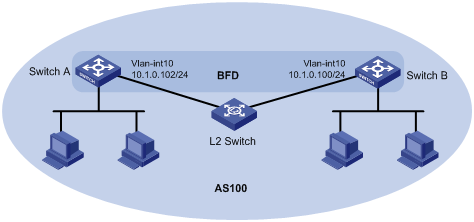
Enable BFD control packet mode on Switch A
and Switch B to help BGP detect the link failure quickly.
Figure 6 Network diagram
This configuration example was created and
verified on S12500-CMW710-R7129.
In BFD control packet mode, at least one
end must operate in active mode for a BFD session to be established.
# Create a VLAN interface and configure its
IP address.
<SwitchA> system-view
[SwitchA] vlan 10
[SwitchA-vlan10] port GigabitEthernet
3/0/1
[SwitchA-vlan10] quit
[SwitchA] interface GigabitEthernet
3/0/1
[SwitchA-GigabitEthernet3/0/1] undo
shutdown
[SwitchA-GigabitEthernet3/0/1] quit
[SwitchA] interface vlan-interface 10
[SwitchA-Vlan-interface10] ip address
10.1.0.102 24
[SwitchA–Vlan-interface10] undo
shutdown
[SwitchA-Vlan-interface10] quit
# Configure BGP basic functions and enable
BFD.
[SwitchA] bgp 100
[SwitchA-bgp] peer 10.1.0.100
as-number 100
[SwitchA-bgp]
ipv4-family unicast
[SwitchA-bgp-ipv4]
peer 10.1.0.100 enable
[SwitchA-bgp-ipv4]
quit
[SwitchA-bgp] peer 10.1.0.100 bfd
[SwitchA-bgp] quit
# Specify the mode for establishing a BFD
session.
[SwitchA] bfd session init-mode
active
# Configure the minimum interval for
transmitting single-hop BFD control packets.
[SwitchA] interface vlan-interface 10
[SwitchA-Vlan-interface10] bfd
min-transmit-interval 100
# Configure the minimum interval for
receiving single-hop BFD control packets.
[SwitchA-Vlan-interface10] bfd
min-receive-interval 100
# Configure the single-hop detection time
multiplier.
[SwitchA-Vlan-interface10] bfd
detect-multiplier 3
[SwitchA-Vlan-interface10] quit
# Create a VLAN interface and configure its
IP address.
<SwitchB> system-view
[SwitchB] vlan 10
[SwitchB-vlan10] port GigabitEthernet
3/0/2
[SwitchB-vlan10] quit
[SwitchB] interface GigabitEthernet
3/0/2
[SwitchB-GigabitEthernet3/0/2] undo
shutdown
[SwitchB-GigabitEthernet3/0/2] quit
[SwitchB] interface vlan-interface 10
[SwitchB–Vlan-interface10] undo
shutdown
[SwitchB-Vlan-interface10] ip address
10.1.0.100 24
[SwitchB-Vlan-interface10] quit
# Configure BGP basic functions and enable
BFD.
[SwitchB] bgp 100
[SwitchB-bgp] peer 10.1.0.102
as-number 100
[SwitchB-bgp]
ipv4-family unicast
[SwitchB-bgp-ipv4]
peer 10.1.0.102 enable
[SwitchB-bgp-ipv4]
quit
[SwitchB-bgp]
peer 10.1.0.102 bfd
[SwitchB-bgp] quit
# Specify the mode for establishing a BFD
session.
[SwitchB] bfd session init-mode
active
# Configure the minimum interval for
transmitting single-hop BFD control packets.
[SwitchB] interface vlan 10
[SwitchB-Vlan-interface10] bfd
min-transmit-interval 100
# Configure the minimum interval for
receiving single-hop BFD control packets.
[SwitchB-Vlan-interface10] bfd
min-receive-interval 100
# Configure the single-hop detection time
multiplier.
[SwitchB-Vlan-interface10] bfd
detect-multiplier 3
[SwitchB-Vlan-interface10] quit
# Display BGP peer information.
[SwitchA] display bgp peer ipv4 verbose
Peer: 10.1.0.100
Local: 2.2.2.2
Type: IBGP link
BGP version 4, remote router
ID 1.1.1.1
BGP current state:
Established, Up for 01h51m18s
BGP current event:
RecvKeepalive
BGP last state: OpenConfirm
Port: Local - 1024
Remote - 179
Configured: Active Hold
Time: 180 sec Keepalive Time: 60 sec
Received : Active Hold
Time: 180 sec
Negotiated: Active Hold
Time: 180 sec Keepalive Time:60 sec
Peer optional capabilities:
Peer support bgp multi-protocol
extended
Peer support bgp route
refresh capability
Peer support bgp route AS4
capability
Address family IPv4 Unicast:
advertised and received
Received: Total 100 messages, Update
messages 0
Sent: Total 111 messages, Update
messages 0
Maximum allowed prefix number:
4294967295
Threshold: 75%
Minimum time between advertisement
runs is 15 seconds
Optional capabilities:
Multi-protocol extended capability has been enabled
Route refresh capability has been
enabled
Peer Preferred Value: 0
BFD: Enabled
Routing policy configured:
No routing policy is configured
# Display BFD session information.
[SwitchA] display bfd session verbose
Total Session Num: 1 Up Session
Num: 1 Init Mode: Active
IPv4 Session Working Under Ctrl Mode:
Local Discr:
12 Remote Discr: 3
Source IP:
10.1.0.102 Destination IP: 10.1.0.100
Session State:
Up Interface: Vlan-interface10
Min Tx Inter:
1000ms Act Tx Inter: 1000ms
Min Rx Inter:
10ms Detect Inter: 3000ms
Rx Count:
160 Tx Count: 165
Connect Type:
Direct Running Up for: 00:02:18
Hold Time: 2553ms Auth
mode: None
Detect Mode:
Async Chassis/Slot: 1/0
Protocol: BGP
Diag Info: No Diagnostic
[SwitchB] display bfd session verbose
Total Session Num: 1 Up Session
Num: 1 Init Mode: Active
IPv4 Session Working Under Ctrl Mode:
Local Discr:
3 Remote Discr: 12
Source IP:
10.1.0.100 Destination IP: 10.1.0.102
Session State:
Up Interface: Vlan-interface10
Min Tx Inter: 1000ms
Act Tx Inter: 1000ms
Min Rx Inter:
10ms Detect Inter: 3000ms
Rx Count:
188 Tx Count: 185
Connect Type:
Direct Running Up for: 00:02:39
Hold Time:
2560ms Auth mode: None
Detect Mode:
Async Chassis/Slot: 1/0
Protocol: BGP
Diag Info: No Diagnostic
The output shows that a BFD session is
created and is up.
# When the link between Switch B and the
Layer 2 switch fails, view BFD log information.
%Jan 7 13:45:42:319 2009 125/6697
BFD/4/LOG:Sess[10.1.0.102/10.1.0.100,Vlan10,Ctrl], Sta: UP->DOWN, Diag: 5
%Jan 7 13:45:42:439 2009 125/6697
RM/3/RMLOG:
BGP.: 10.1.0.100 State is changed
from ESTABLISHED to IDLE.
The output shows that BFD can quickly
detect the failure and notify BGP of the failure.
· Switch A:
#
vlan 10
#
interface Vlan-interface10
ip address 10.1.0.102
255.255.255.0
bfd min-transmit-interval 100
bfd min-receive-interval 100
bfd detect-multiplier 3
#
interface GigabitEthernet3/0/1
port link-mode bridge
port access vlan 10
#
bgp 100
undo synchronization
peer 10.1.0.100 as-number 100
peer 10.1.0.100 bfd
#
ipv4-family unicast
peer 10.1.0.100 enable
#
· Switch B:
#
vlan 10
#
interface Vlan-interface10
ip address 10.1.0.100
255.255.255.0
bfd min-transmit-interval 100
bfd min-receive-interval 100
bfd detect-multiplier 3
#
interface GigabitEthernet3/0/2
port link-mode bridge
port access vlan 10
#
bgp 100
undo synchronization
peer 10.1.0.102 as-number 100
peer 10.1.0.102 bfd
#
ipv4-family unicast
peer 10.1.0.102 enable
#
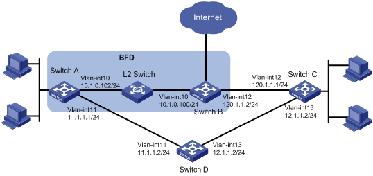
As shown in Figure 7:
· Switch A has two paths to reach Switch C: one
through Switch B, and the other through Switch D.
· Switch A and Switch C access the Internet
through Switch B.
· A Layer 2 switch connects Switch A and Switch B.
Because Switch B does not support BFD, enable
BFD echo packet mode on Switch A. When the link between
Switch B and the Layer 2 switch fails, Switch A selects Switch D to reach
Switch C.
Figure 7 Network diagram
In this example, BFD echo packet mode is
enabled on Switch A because Switch B does not support BFD. If both Switch A and
Switch B support BFD, use BFD control packet mode instead.
This configuration
example was created and verified on S12500-CMW710-R7129.
# Create VLAN interfaces and configure
their IP addresses.
<SwitchA> system-view
[SwitchA] vlan 10
[SwitchA-vlan10] port GigabitEthernet
4/0/1
[SwitchA-vlan10] quit
[SwitchA] interface GigabitEthernet 4/0/1
[SwitchA-GigabitEthernet4/0/1] undo
shutdown
[SwitchA-GigabitEthernet4/0/1] quit
[SwitchA] interface vlan-interface 10
[SwitchA–Vlan-interface10] undo
shutdown
[SwitchA-Vlan-interface10] ip address
10.1.1.102 24
[SwitchA-Vlan-interface10] quit
[SwitchA] vlan 11
[SwitchA-vlan11] port GigabitEthernet
9/0/48
[SwitchA-vlan11] quit
[SwitchA] interface GigabitEthernet 9/0/48
[SwitchA-GigabitEthernet9/0/48] undo
shutdown
[SwitchA-GigabitEthernet9/0/48] quit
[SwitchA] interface vlan-interface 11
[SwitchA–Vlan-interface11] undo
shutdown
[SwitchA-Vlan-interface11] ip address
11.1.1.1 24
[SwitchA-Vlan-interface11] quit
# Configure the source IP address of BFD
echo packets. The source IP address cannot be on the same network segment as
any local interface's IP address.
[SwitchA] bfd echo-source-ip
10.10.10.10
# Configure two static routes with the same
destination IP address and different preferences. Configure the BFD echo packet
mode for the preferred static route (Switch A –> Switch B –>
Switch C).
[SwitchA] ip route-static 120.1.1.1
32 Vlan-interface 10 10.1.1.100 bfd echo-packet preference 40
[SwitchA] ip
route-static 120.1.1.1 32 Vlan-interface 11 11.1.1.2 preference 50
# Configure the minimum interval for
receiving BFD echo packets.
[SwitchA] interface vlan-interface 10
[SwitchA-Vlan-interface10] bfd
min-echo-receive-interval 10
# Configure the single-hop detection time
multiplier.
[SwitchA-Vlan-interface10] bfd
detect-multiplier 3
[SwitchA-Vlan-interface10] quit
# Display static route information.
[SwitchA] display ip routing-table
protocol static verbose
Summary Count : 1
Destination: 120.1.1.1/32
Protocol:
Static Process ID: 0
SubProtID:
0x0 Age: 00h05m06s
Cost:
0 Preference: 40
Tag:
0 State: Active Adv
OrigTblID:
0x0 OrigVrf: default-vrf
TableID:
0x2 OrigAs: 0
NBRID: 0x11000000
LastAs: 0
AttrID:
0xffffffff Neighbor: 0.0.0.0
Flags:
0x10040 OrigNextHop: 10.1.1.100
Label:
NULL RealNextHop: 10.1.1.100
BkLabel:
NULL BkNextHop: N/A
Tunnel ID:
Invalid Interface: Vlan-interface10
BkTunnel ID:
Invalid BkInterface: N/A
The output shows that the static route with
a lower preference is active.
# Display BFD session information.
[SwitchA] display bfd session verbose
Total Session Num: 1 Up Session Num: 1 Init Mode: Active
IPv4 Session Working Under Echo Mode:
Local Discr: 13
Source IP:
10.1.1.102 Destination IP: 10.1.1.100
Session State:
Up Interface: Vlan-interface10
Hold Time:
28ms Act Tx Inter: 10ms
Min Rx Inter:
10ms Detect Inter: 30ms
Rx Count:
57914 Tx Count: 58052
Connect Type:
Direct Running Up for: 00:06:27
Detect Mode:
Async Chassis/Slot: 1/0
Protocol: STATIC
Diag Info: No Diagnostic
The output shows that a BFD session is
created and is up.
# When the link between Switch B and the Layer
2 switch fails, view BFD log information.
%Jan 7 14:23:39:786 2009 125/6697
BFD/4/LOG:Sess[10.1.1.102/10.1.1.100,Vlan10,Echo], Sta: UP->DOWN, Diag: 5
The output shows that the BFD session goes
down.
# Display static route information.
[SwitchA] display ip routing-table protocol
static verbose
Summary Count : 1
Destination: 120.1.1.1/32
Protocol:
Static Process ID: 0
SubProtID:
0x0 Age: 00h01m09s
Cost:
0 Preference: 50
Tag:
0 State: Active Adv
OrigTblID:
0x0 OrigVrf: default-vrf
TableID:
0x2 OrigAs: 0
NBRID:
0x11000001 LastAs: 0
AttrID:
0xffffffff Neighbor: 0.0.0.0
Flags:
0x10040 OrigNextHop: 11.1.1.2
Label:
NULL RealNextHop: 11.1.1.2
BkLabel:
NULL BkNextHop: N/A
Tunnel ID:
Invalid Interface: Vlan-interface11
BkTunnel ID:
Invalid BkInterface: N/A
The output shows that the static route with
preference 50 and output interface VLAN-interface 11 becomes active. Switch A
communicates with Switch C through Switch D.
#
vlan 10
#
vlan 11
#
bfd echo-source-ip 10.10.10.10
#
interface Vlan-interface10
ip address 10.1.1.102 255.255.255.0
bfd min-echo-receive-interval 10
bfd detect-multiplier 3
#
interface Vlan-interface11
ip address 11.1.1.1 255.255.255.0
#
interface GigabitEthernet4/0/1
port link-mode bridge
port access vlan 10
#
interface GigabitEthernet9/0/48
port link-mode bridge
port access vlan 11
#
ip route-static 120.1.1.1
255.255.255.255 Vlan-interface10 10.1.1.100 bfd echo-packet preference 40
ip route-static 120.1.1.1
255.255.255.255 Vlan-interface11 11.1.1.2 preference 50
#
· H3C S12500 Routing Switch Series High
Availability Configuration Guide
· H3C S12500 Routing Switch Series High
Availability Command Reference
· H3C S12500 Routing Switch Series Layer 3—IP Routing
Configuration Guide
· H3C S12500 Routing Switch Series Layer 3—IP Routing Command
Reference
 Login
Login
