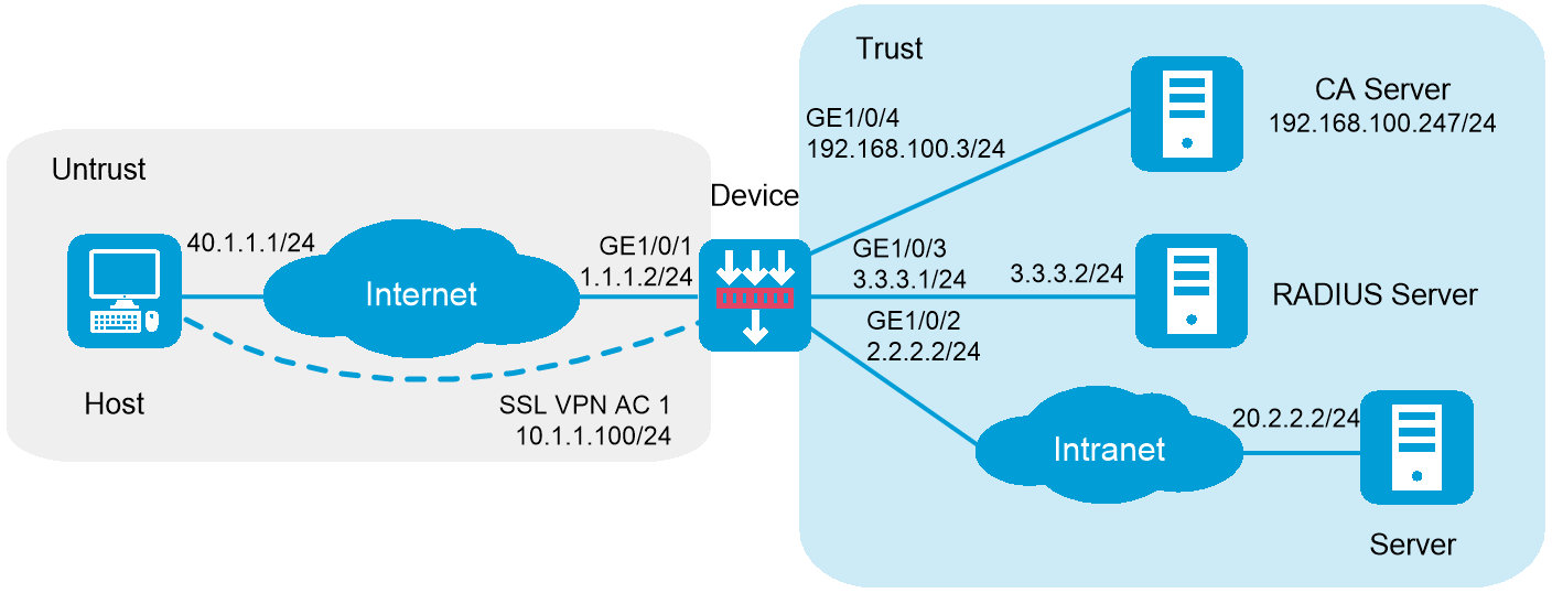
As shown in Figure 1, the device acts as an SSL VPN gateway that connects the public network and the private network. On the private network, a Windows Server 2008 R2 CA server and a RADIUS server that runs IMC PLAT 7.3 (E0504) are deployed. Users need secure access to the internal server (20.2.2.2/24) in IP access mode.
Perform the following tasks:
Request an SSL server certificate for the device from the CA server.
Configure the device to require that users pass certificate authentication for IP access.
Configure the device to use the RADIUS server to perform remote authentication and authorization for IP access users.
Configure the SSL VPN IP access service on the device to allow users to access the internal server in IP access mode.
Figure 1 Network diagram (RADIUS authentication)
This configuration example was created and verified on F9900 of the F5000-AI120 device.
The IP address pool configured for client address allocation must meet the following requirements:
The address range of the address pool cannot be on the same subnet as the IP address used on the client host.
The IP addresses in the address pool do not conflict with the IP addresses used on the device.
The address range of the address pool cannot be on the same subnet as the IP address of the internal server.
The SSL VPN AC interface must be added to the correct security zone (Untrust, in this example).
Make sure the internal server can reach subnet 10.1.1.0/24 where the IP address pool for SSL VPN clients resides.
Assign IP addresses to interfaces and add the interfaces to security zones.
# On the top navigation bar, click the Network tab.
# From the navigation pane, select Interface Configuration > Interfaces.
# Click the Edit icon for GE 1/0/1.
# In the dialog box that opens, configure the interface:
Select the Untrust security zone.
On the IPv4 Address tab, enter the IP address and mask length of the interface. In this example, enter 1.1.1.2/24.
Use the default settings for other parameters.
Click OK.
# Add GE 1/0/2 to the Trust security zone and set its IP address to 2.2.2.2/24 in the same way you configure GE 1/0/1.
# Add GE 1/0/3 to the Trust security zone and set its IP address to 3.3.3.1/24 in the same way you configure GE 1/0/1.
# Add GE 1/0/4 to the Trust security zone and set its IP address to 192.168.100.3/24 in the same way you configure GE 1/0/1.
Configure settings for routing:
This example configures static routes.
# On the top navigation bar, click Network.
# From the navigation pane, select Routing > Static Routing.
# On the IPv4 Static Routing tab, click Create.
# In the dialog box that opens, configure a static IPv4 route to reach 40.1.1.1:
Enter destination IP address 40.1.1.1.
Enter mask length 24.
Enter next hop address 1.1.1.3.
Use the default settings for other parameters.
Click OK.
# Configure a static IPv4 route to reach 20.2.2.2:
Enter destination IP address 20.2.2.2.
Enter mask length 24.
Enter next hop address 2.2.2.3.
Use the default settings for other parameters.
Click OK.
Create security policies:
# On the top navigation bar, click Policies.
# From the navigation pane, select Security Policies > Security Policies.
# Click Create.
# In the dialog box that opens, configure a security policy named untrust-local to permit the specified traffic from the Untrust to Local security zones:
Enter policy name untrust-local.
Select source zone Untrust.
Select destination zone Local.
Select type IPv4.
Select action Permit.
Select source IPv4 address 40.1.1.1.
Select destination IPv4 address 1.1.1.2.
Use the default settings for other parameters.
# Click OK.
# Create security policy untrust-trust to permit the specified traffic from the Untrust to Trust security zones:
Enter policy name untrust-trust.
Select source zone Untrust.
Select destination zone Trust.
Select type IPv4.
Select action Permit.
Select source IPv4 address 10.1.1.0/24.
Select destination IPv4 address 20.2.2.2/24.
Use the default settings for other parameters.
# Click OK.
Request a server certificate for the device:
Create a certificate subject:
# On the top navigation bar, click Objects.
# From the navigation pane, select PublicKey Cert > PKI > Certificate Subject.
# Click Create.
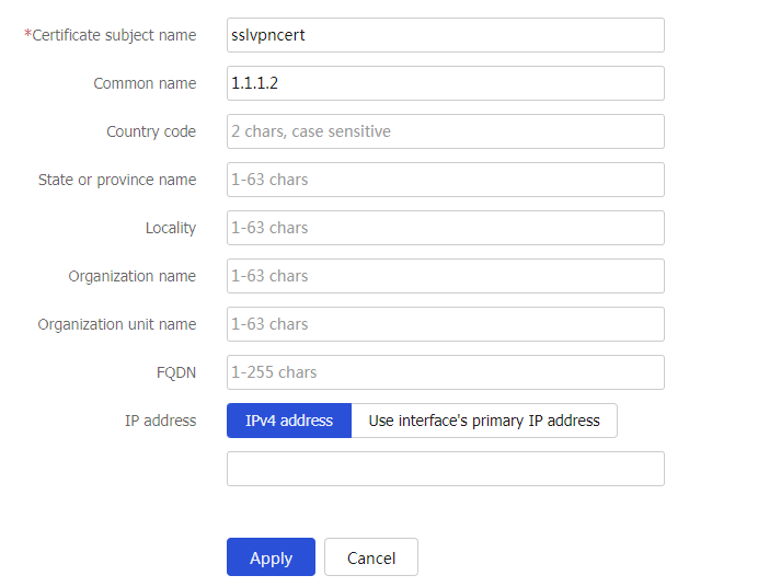
# Create a certificate subject as shown in Figure 2, and the click OK.
Figure 2 Creating a certificate subject
Create a PKI domain:
# On the Certificate page, click Create PKI domain.
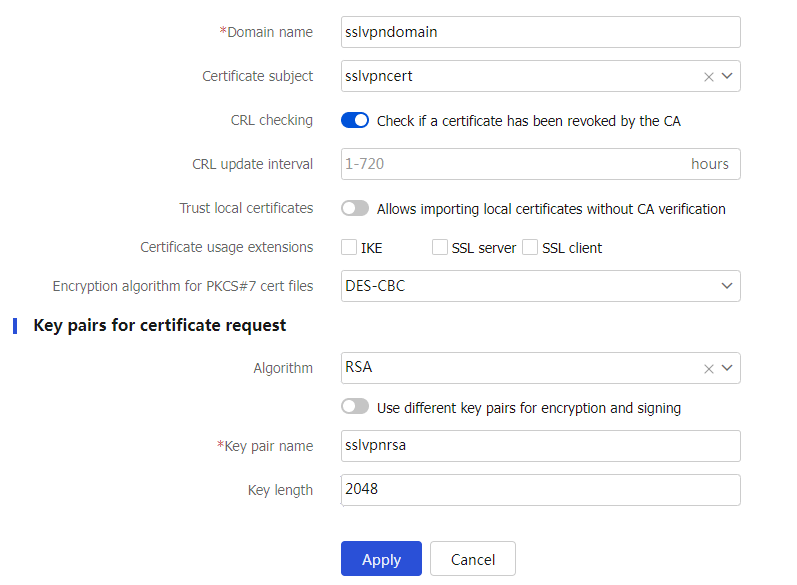
# Create a PKI domain as shown in Figure 3, and then click OK.
Figure 3 Creating a PKI domain
Create a certificate request:
# On the Certificate page, click Submit Cert Request.
# Configure the certificate request settings as shown in Figure 4.
Figure 4 Creating a certificate request
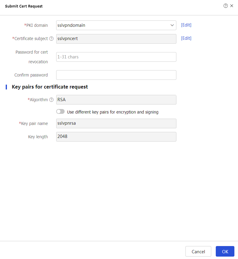
# Click OK.
The certificate request content will be displayed, as shown in Figure 5.
Figure 5 Certificate request content
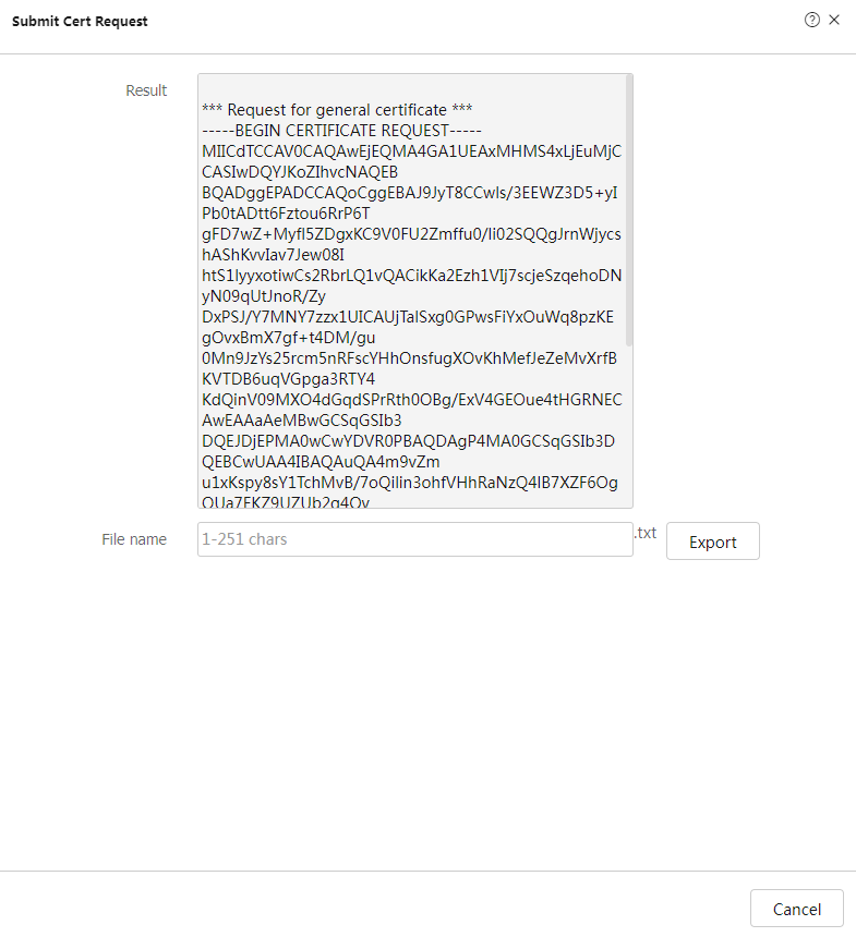
# Copy the certificate request content and click OK.
Request a server certificate from the CA:
# Enter http://192.168.100.247/certsrv in the browser address bar.
# On the certificate service home page shown in Figure 6, click Request a certificate.
Figure 6 Certificate service home page

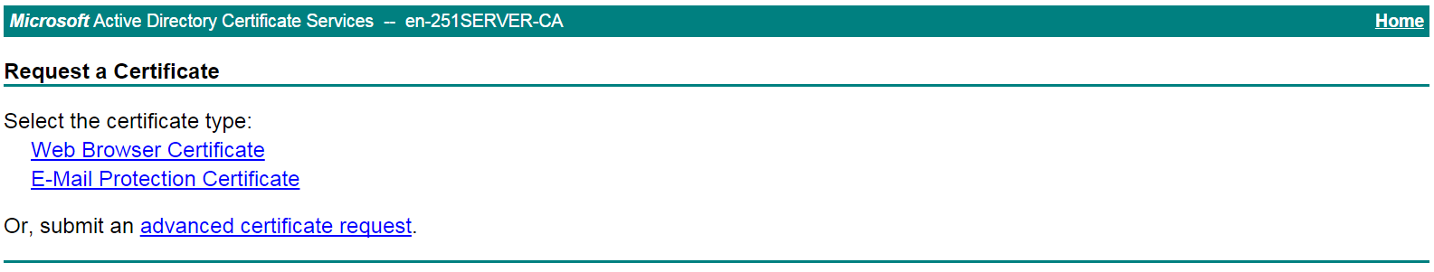
# On the Request a Certificate page shown in Figure 7, click advanced certificate request.
Figure 7 Request a Certificate page
# Paste the previously copied certificate request content in the Base-64-encoded certificate request CMC or PKCS # 10 or PKCS # 7) field, as shown in Figure 8.
Figure 8 Pasting the certificate request content
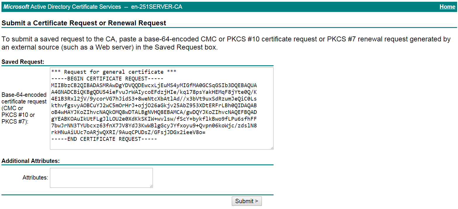
# Click Submit.
After the certificate request is approved by the CA administrator, enter http://192.168.100.247/certsrv in the browser address bar.
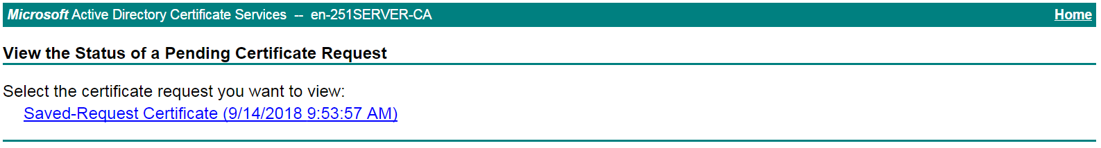
# On the certificate service home page shown in Figure 9, click View the status of a pending certificate request.
Figure 9 Certificate service home page

# Select the certificate request you want to view.
Figure 10 View the Status of a Pending Certificate Request page
The Certificate Issued page opens, indicating that the requested server certificate has been issued, as shown in Figure 11.
Figure 11 Certificate Issued page
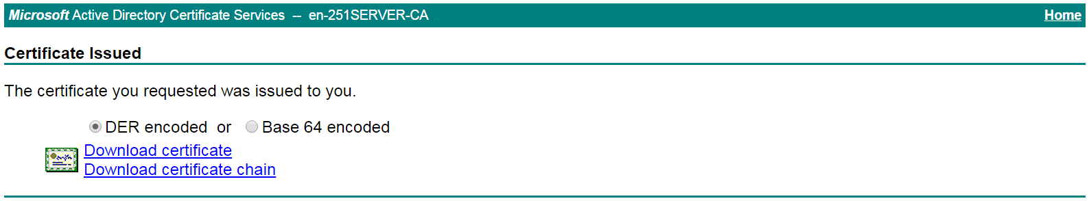
# Click Download certificate to download the server certificate and save it locally.
Download the CA certificate:
# Enter http://192.168.100.247/certsrv in the browser address bar.
# On the certificate service home page shown in Figure 12, click Download a CA certificate, certificate chain, or CRL.
Figure 12 Certificate service home page

# On the Download a CA certificate, certificate chain, or CRL page shown in Figure 13, click Download CA certificate.
Figure 13 Download a CA certificate, certificate chain, or CRL page
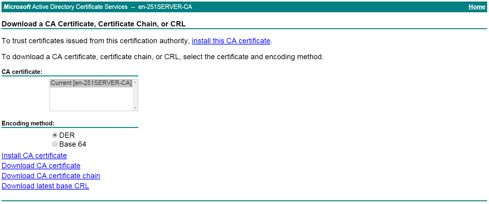
# Save the downloaded CA certificate locally.
Import the CA certificate and server certificate to the PKI domain:
Import the CA certificate:
# On the top navigation bar, click Objects.
# From the navigation pane, select PublicKey Cert > PKI > Certificate.
# Click Import certificate.
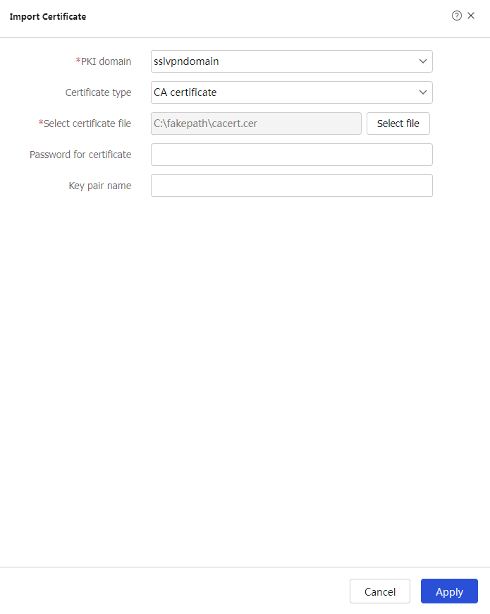
# Import the locally saved CA certificate, as shown in Figure 14, and then click Apply.
Figure 14 Importing the CA certificate
Import the server certificate:
# On the Certificate page, click Import certificate.
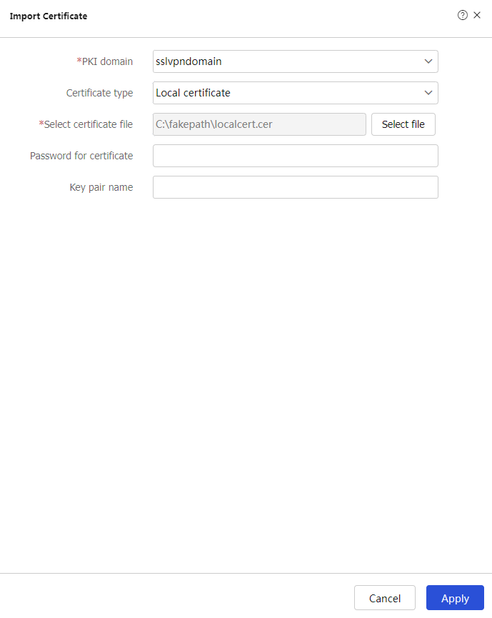
# Import the locally saved server certificate, as shown in Figure 15, and then click Apply.
Figure 15 Importing the server certificate
Configure an SSL server policy:
# On the top navigation bar, click Objects.
# From the navigation pane, select SSL > SSL Server Policies.
# Click Create.
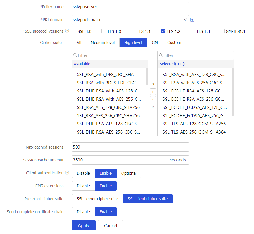
# Configure an SSL server policy as shown in Figure 16, and then click Apply.
Figure 16 Creating an SSL server policy
Configure a RADIUS scheme:
# On the top navigation bar, click Objects.
# From the navigation pane, select User > Authentication > RADIUS.
# Click Create.
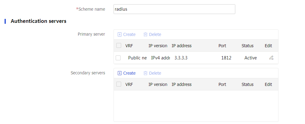
# Configure a RADIUS scheme named radius:
Set the authentication server as shown in Figure 17.
Set the global shared key for authentication to 123456.
Figure 17 Configuring a RADIUS scheme
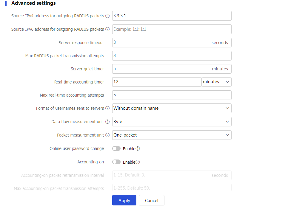
# Configure the advanced settings for the RADIUS scheme in the Advanced settings area, as shown in Figure 18.
Figure 18 Configuring the advanced settings for the RADIUS scheme
# Click Apply.
Create an ISP domain:
# On the top navigation bar, click Objects.
# From the navigation pane, select User > Authentication > ISP Domains.
# Click Create.
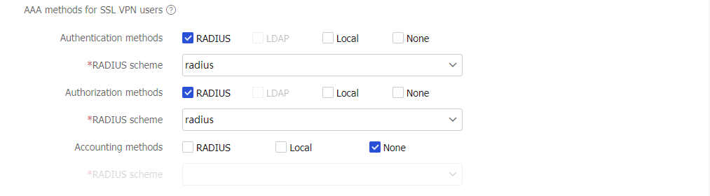
# In the dialog box that opens, configure an ISP domain named sslvpn as shown in Figure 19 and Figure 20:
Specify the domain name as sslvpn.
Select access type SSL VPN.
Select RADIUS for authentication and authorization methods and select RADIUS scheme radius.
Select None for the accounting method.
Figure 19 Configuring an ISP domain (1)

Figure 20 Configuring an ISP domain (2)
Create a user group:
# On the top navigation bar, click Objects.
# From the navigation pane, select User > User Management > Local Users.
# Click the User Group tab.
# Click Create.
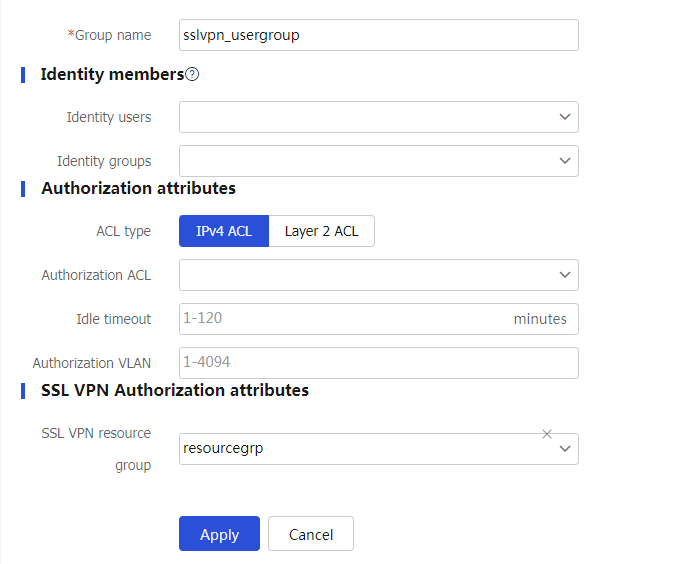
# Create a user group named sslvpn_usergroup and specify SSL VPN resource group resourcegrp for the user group, as shown in Figure 21.
# Click Apply.
Figure 21 Creating a user group
Configure the SSL VPN gateway:
# On the top navigation bar, click Network.
# From the navigation pane, select VPN > SSL VPN > SSL VPN Gateways.
# Click Create.
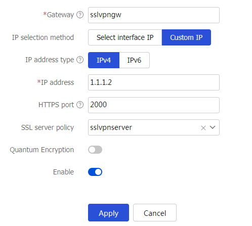
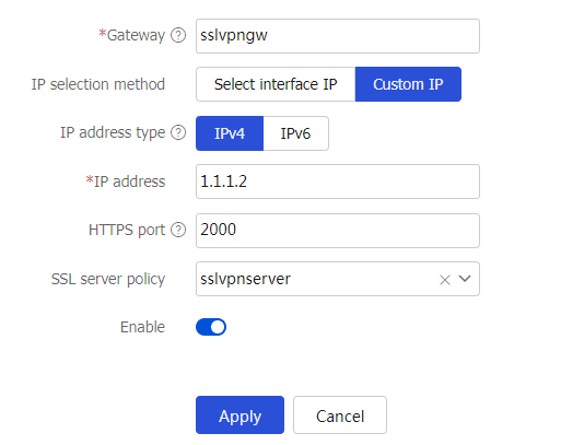
# Create an SSL VPN gateway as shown in Figure 22, and then click Apply.
Figure 22 Creating an SSL VPN gateway
Create an SSL VPN AC interface:
# On the top navigation bar, click Network.
# From the navigation pane, select VPN > SSL VPN > SSL VPN AC Interfaces.
# Click Create.
# In the Create Interfaces dialog box that opens, enter 1 in the Interface number field and click OK.
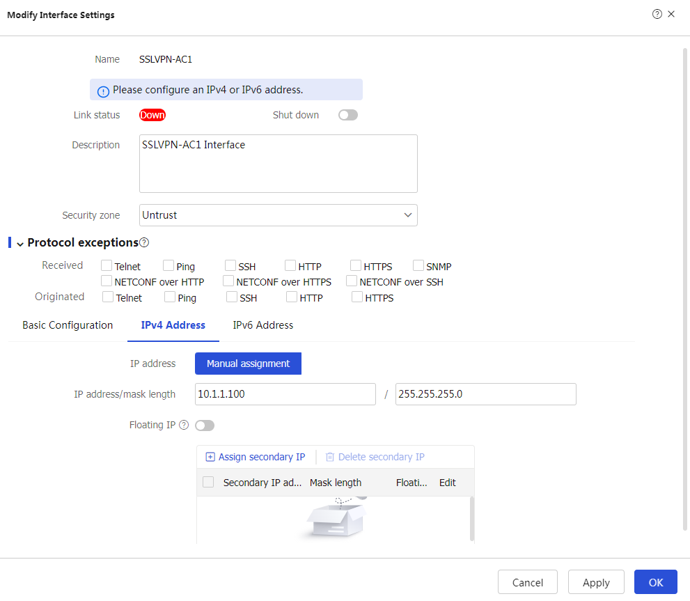
# In the Modify Interface Settings dialog box, configure the parameters for the SSL VPN AC interface.
# Click OK.
Figure 23 Configuring parameters for the SSL VPN AC interface (1)
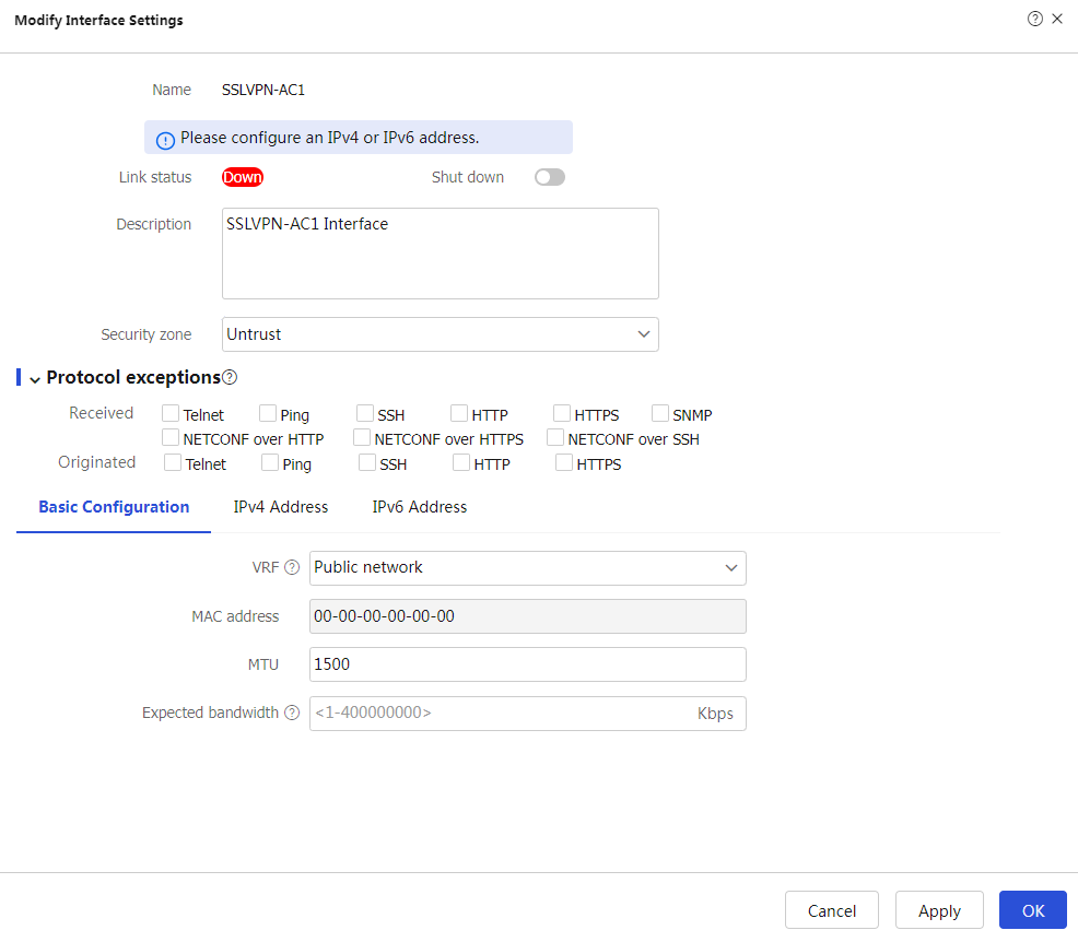
Figure 24 Configuring basic settings for the SSL VPN AC interface (2)
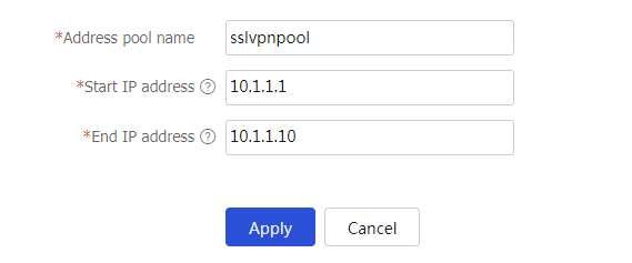
Create an address pool for IP access users:
# On the top navigation bar, click Network.
# From the navigation pane, select VPN > SSL VPN > IP Access Address Pools.
# Click Create.
# Create an IP access address pool as shown in Figure 25, and then click Apply.
Figure 25 Creating an IP access address pool
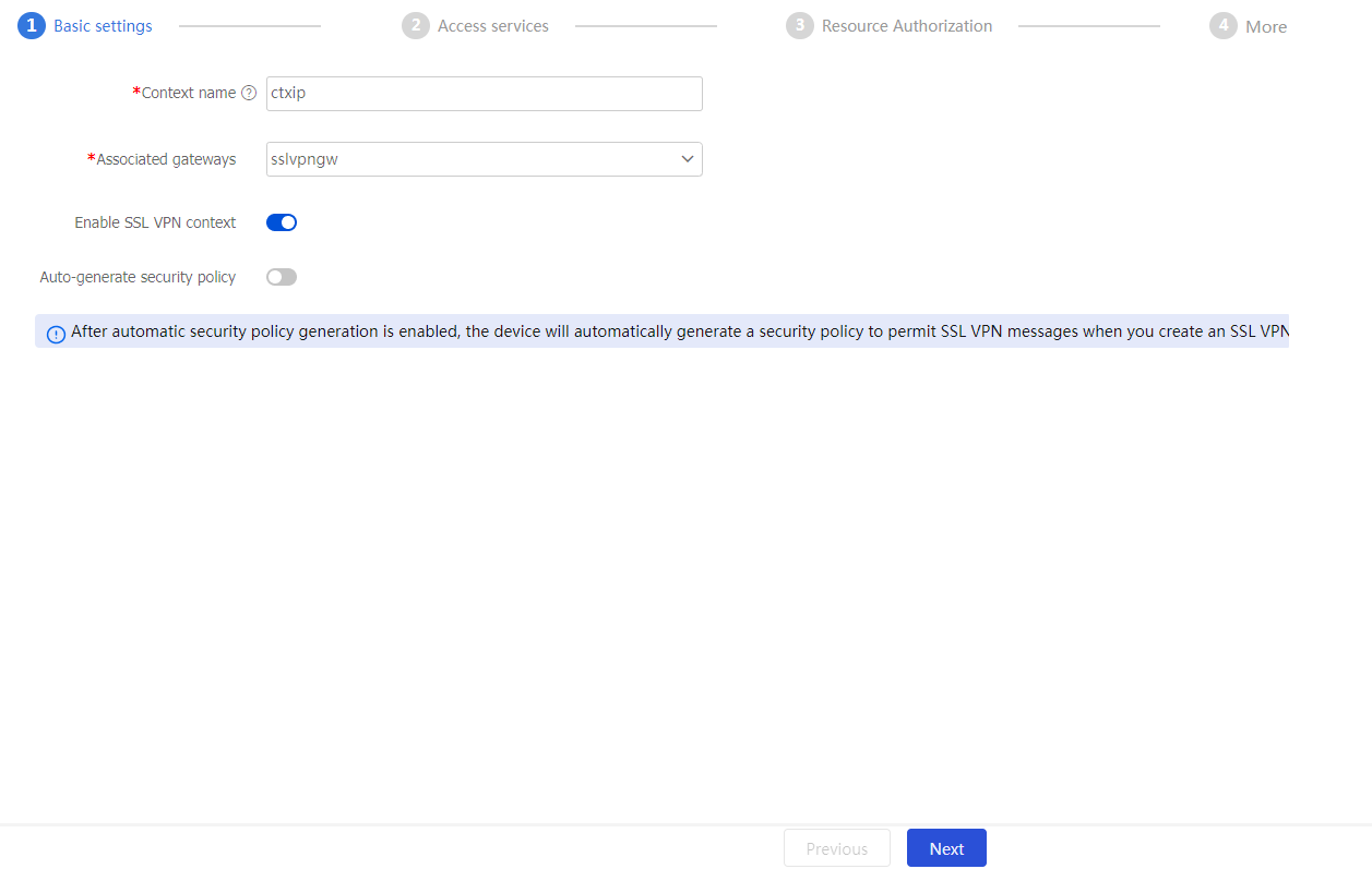
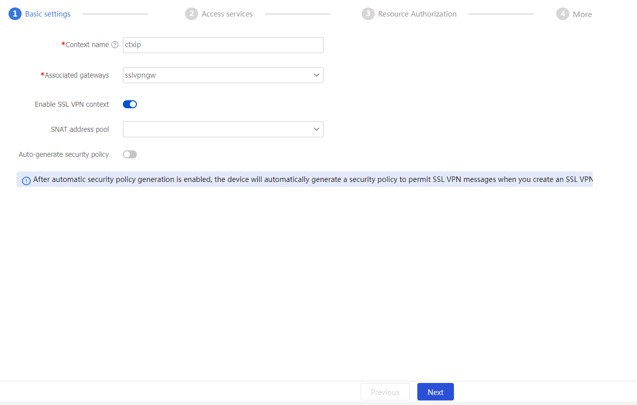
Configure an SSL VPN context:
On the top navigation bar, click Network.
From the navigation pane, select VPN > SSL VPN > SSL VPN Contexts.
Click Create.
Configure the basic settings for the SSL VPN context as shown in Figure 26, and then click Next.
Figure 26 Configuring basic settings for an SSL VPN context
Enable the tunnel service and configure tunnel service parameters, as shown in Figure 19.
Figure 27 Configuring tunnel service settings
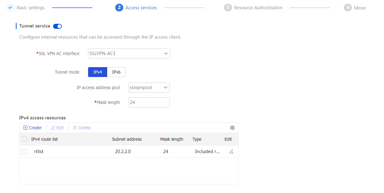
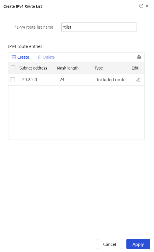
In the IPv4 access resources area, create an IPv4 route list named rtlist.
# Click Create in the IPv4 access resources area.
# Specify the IPv4 route list name and create IPv4 route entries.
# Click Apply.
Figure 28 Creating an IPv4 route list
Click Next, and then configure an resource group.
# On the Resource groups page, click Create.
# Specify the resource group name as resourcegrp and configure other resource parameters, as shown in Figure 29. In this example, use IPv4 ACL 3999 to restrict user access to resources with specific IP addresses and ports.
Figure 29 Configuring IP access resources for the IP access service
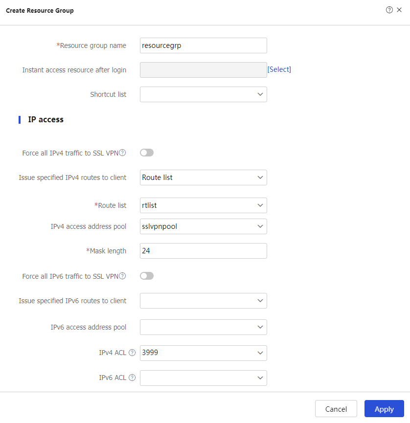
# Click Apply.
Click Next to configure authentication settings.
Figure 30 Configuring authentication settings
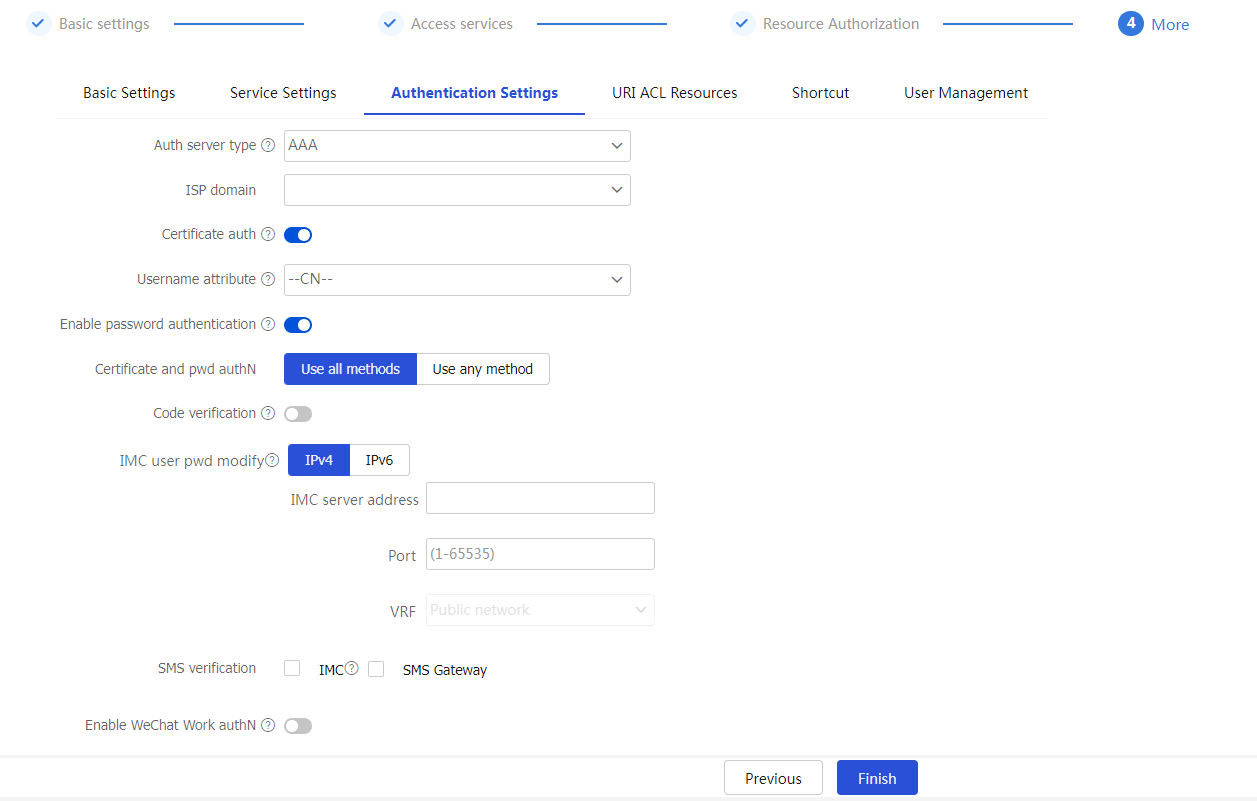
Click Finish.
In this example, the IMC version is iMC PLAT 7.3 (E0504).
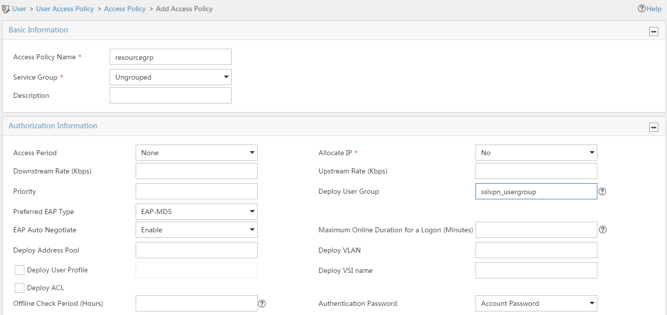
Configure an access policy named resourcegrp:
# Log in to IMC.
# On the top navigation bar, click User.
# From the navigation pane, select User Access Policy > Access Policy.
# Click Add.
# Add an access policy as shown in Figure 33.
# Click OK.
Figure 31 Creating an access policy
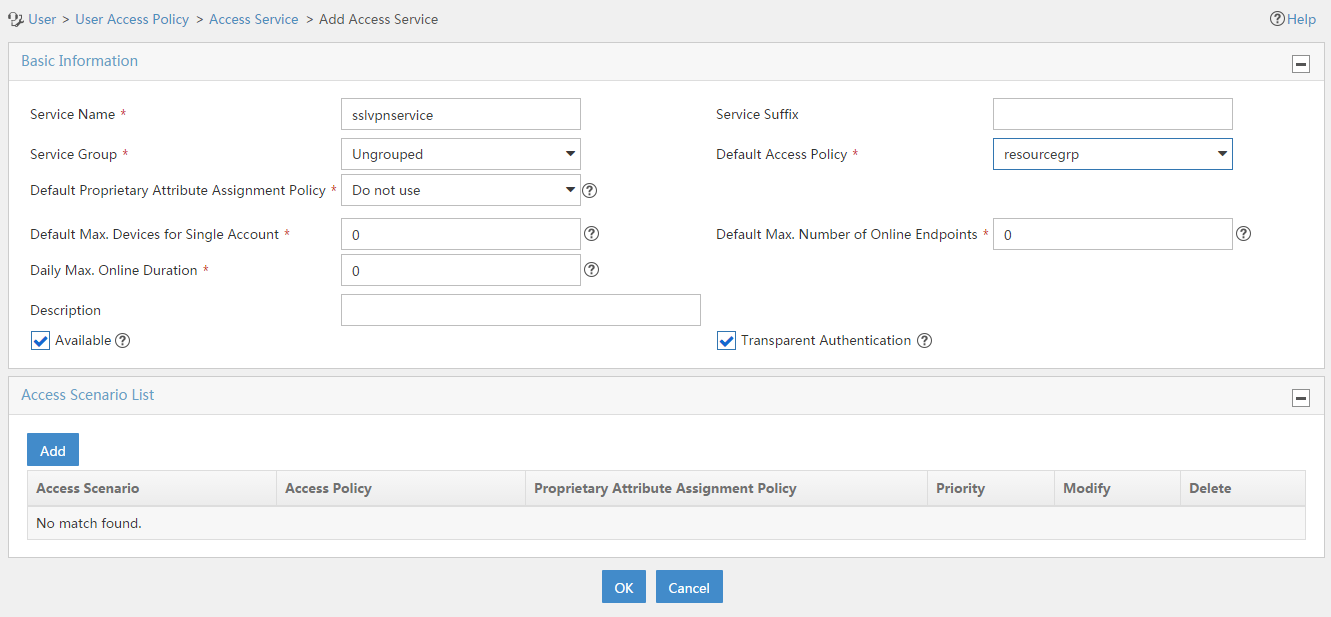
Configure an access service named sslvpnservice:
# On the top navigation bar, click User.
# From the navigation pane, select User Access Policy > Access Service.
# Click Add.
# Add an access service as shown in Figure 34. In this example, specify access policy resourcegrp as the default access policy.
# Click OK.
Figure 32 Creating an access service
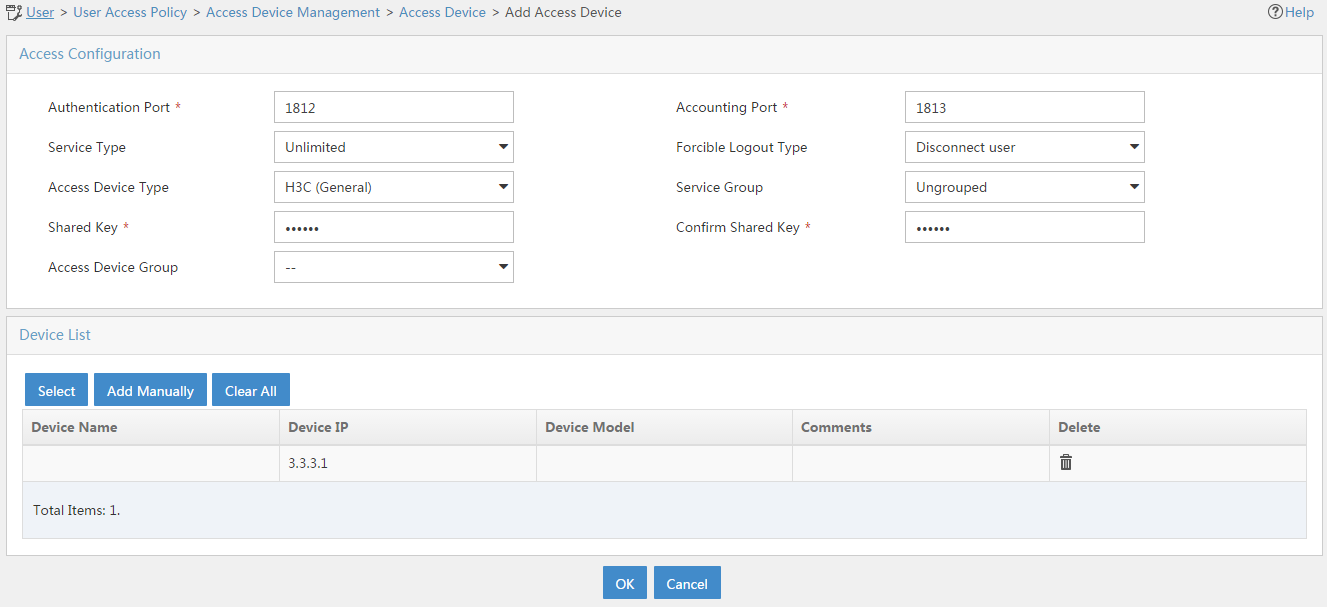
Configure an access device:
# On the top navigation bar, click User.
# From the navigation pane, select User Access Policy > Access Device Management > Access Device.
# Click Add.
# Add an access device as shown in Figure 35. In this example, set the shared key to 123456.
# Click OK.
Figure 33 Configuring an access device
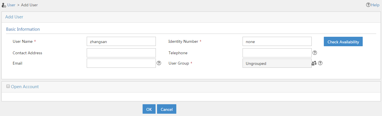
Configure an access user:
# Access the User > Add User page.
# Add a platform user as shown in Figure 36.
# Click OK.
Figure 34 Adding a platform user
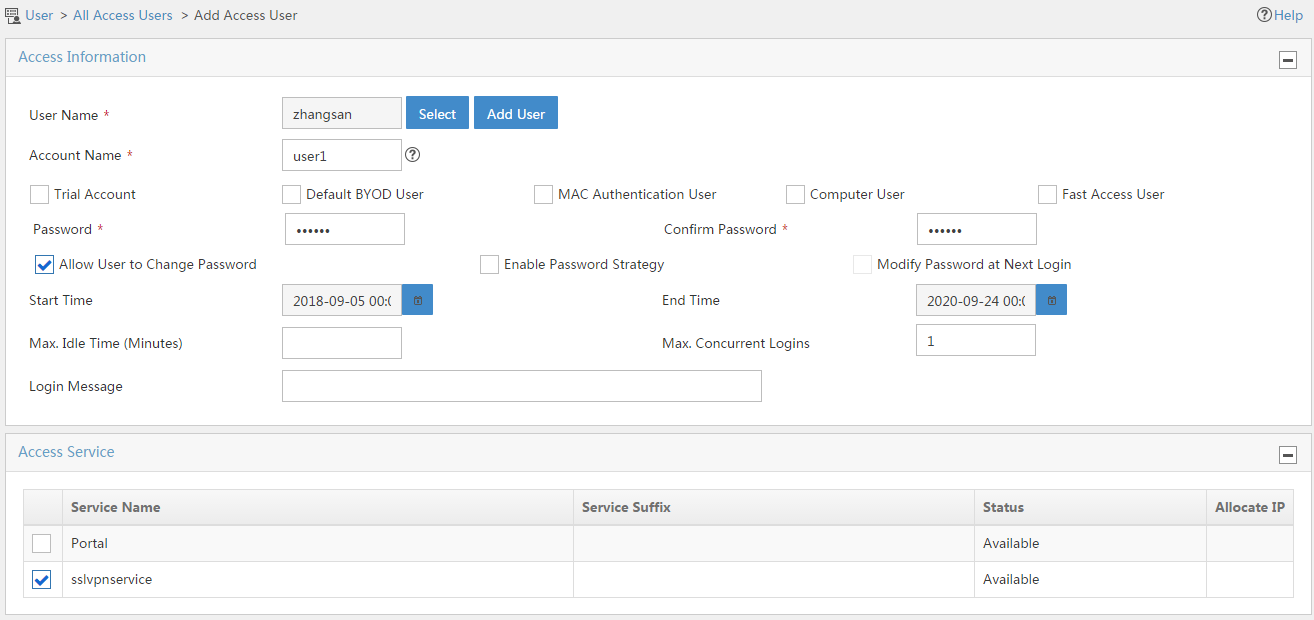
# From the navigation pane, select Access User > All Access Users.
# Click Add.
# Add an access user and assign access service sslvpnservice to the user, as shown in Figure 37.
# Click OK.
Figure 35 Adding an access user
Configure the IP address and gateway address settings for the host and make sure it can reach the SSL VPN gateway and the CA server.
Submit a client certificate request to the CA server:
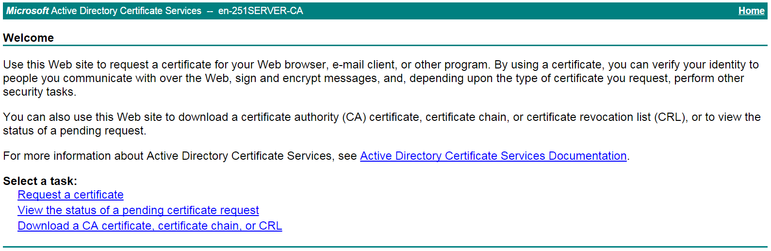
Enter http://192.168.100.247/certsrv in the browser address bar.
On the certificate service home page shown in Figure 38, click Request a certificate.
Figure 36 Certificate service home page

On the Request a Certificate page shown in Figure 39, click advanced certificate request.
Figure 37 Request a Certificate page

Create a client certificate request, as shown in Figure 40.
Figure 38 Creating a client certificate request
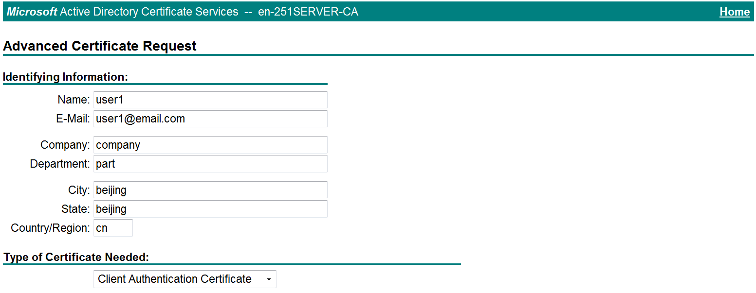
Click Submit.
Install the client certificate on the host:
After the certificate request is approved by the CA administrator, enter http://192.168.100.247/certsrv in the browser address bar.
On the certificate service home page shown in Figure 41, click View the status of a pending certificate request.
Figure 39 Certificate service home page
The View the Status of a Pending Certificate Request page opens, as shown in Figure 42.
Figure 40 View the Status of a Pending Certificate Request page
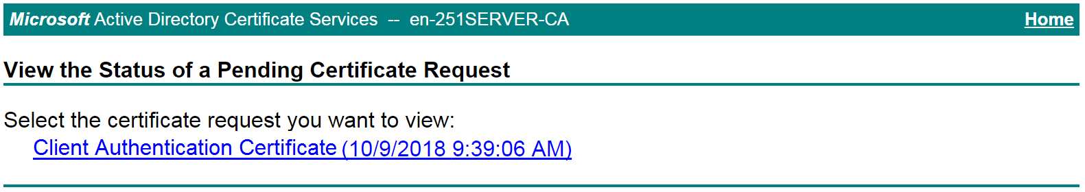
Click the client certificate whose status you want to view.
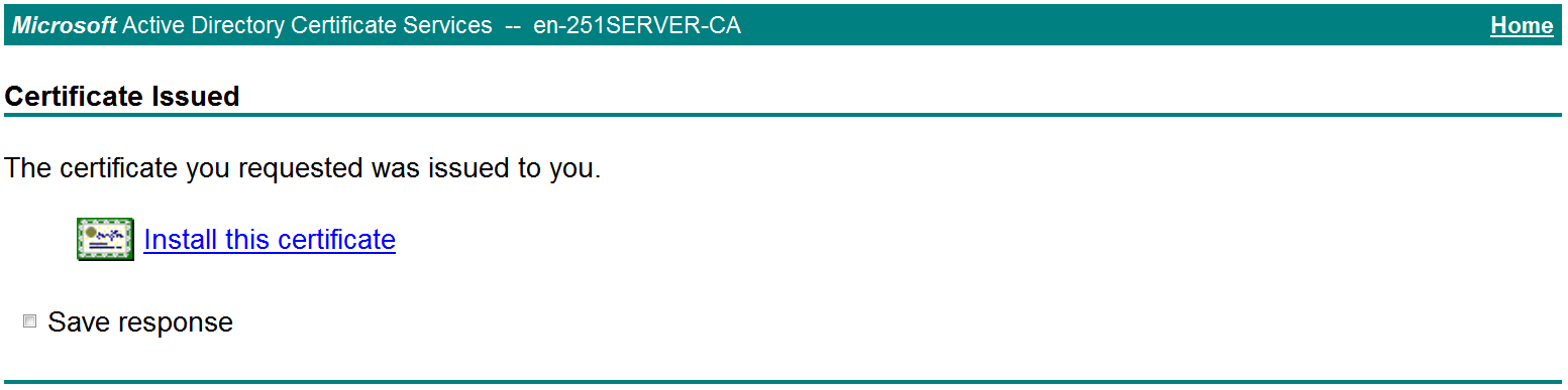
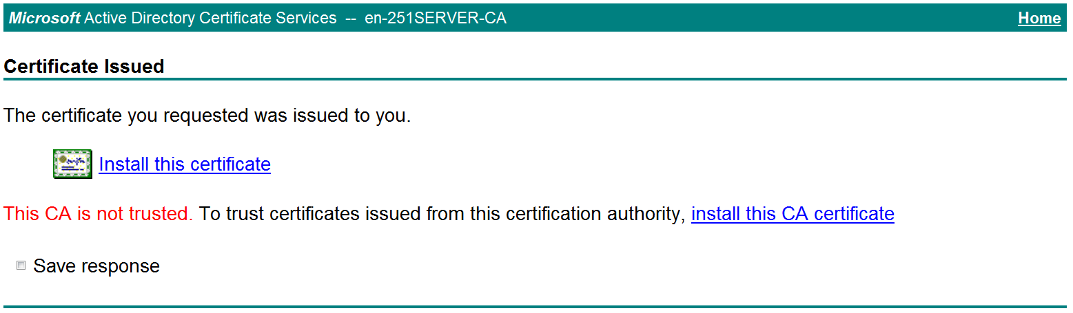
On the Certificate Issued page shown in Figure 43, click Install this certificate to install the client certificate. If the host does not have a CA certificate, the page shown in Figure 44 opens. You must install the CA certificate first.
Figure 41 Installing the client certificate
To install the CA certificate, click install this CA certificate. Then, click Install this certificate to install the client certificate.
Figure 42 Installing the CA certificate and then the client certificate
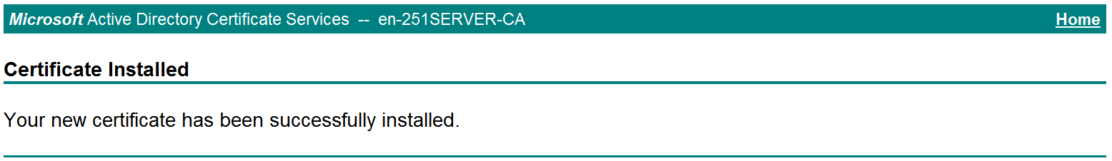
After the client certificate is installed, the Certificate Installed page shown in Figure 45 opens.
Figure 43 Certificate Installed page
In the browser address bar of the host, enter https://1.1.1.2:2000 and press Enter.
Select the client certificate for authentication, and then click OK to go to the Domain List page.
Click domainip to access the login page. Then, enter username user1 and password 123456.
Figure 44 SSL VPN login page
Click Login.
Click START to start the IP client application.
If the host does not have an iNode client installed, the system installs the iNode client, and then starts and connects the iNode client to the SSL VPN gateway.
If the host already has an iNode client installed, the system starts the iNode client and connects it to the SSL VPN gateway directly.
For the first login, you must configure properties and select an authentication mode and a client certificate.
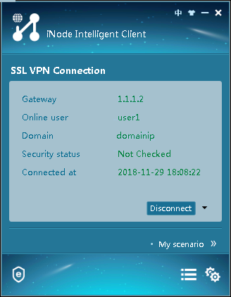
Figure 49 shows that the iNode client is successfully connected to the SSL VPN gateway.
Figure 45 Connecting the iNode client to the SSL VPN gateway