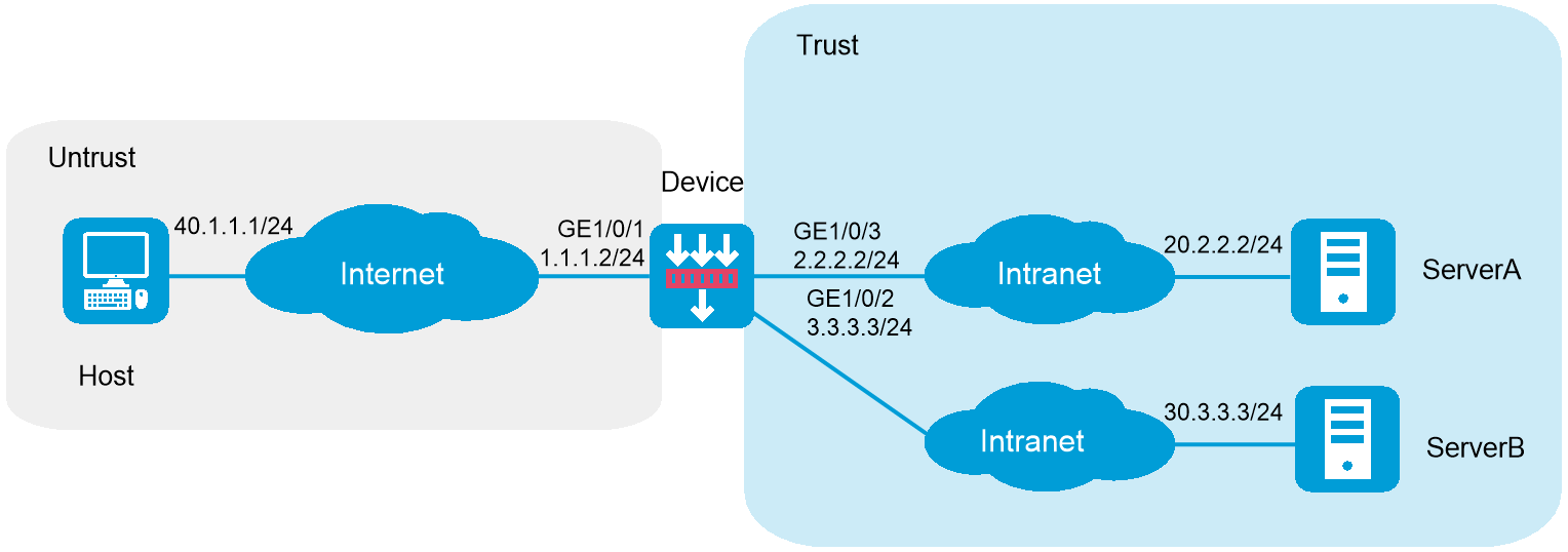
As shown in Figure 1, the device acts as the SSL VPN gateway that connects the public network and the private network. Users need to access resources on internal Web servers Server A and Server B. Both servers use HTTP over port 80.
Configure the SSL VPN Web access service on the device to allow users to access Server A and Server B in Web access mode.
Configure the device to perform local authentication and authorization for Web access users.
The device uses a self-signed SSL server certificate.
This configuration example was created and verified on E9671 of the M9000-X06 device.
Assign IP addresses to interfaces and add the interfaces to security zones:
# On the top navigation bar, click Network.
# From the navigation pane, select Interface Configuration > Interfaces.
# Click the Edit icon for GE 1/0/1.
# In the dialog box that opens, configure the interface:
Select the Untrust security zone.
On the IPv4 Address tab, enter the IP address and mask of the interface. In this example, enter 1.1.1.2/24.
Use the default settings for other parameters.
Click OK.
# Add GE 1/0/2 to the Trust security zone and set its IP address to 3.3.3.3/24 in the same way you configure GE 1/0/1.
# Add GE 1/0/3 to the Trust security zone and set its IP address to 2.2.2.2/24 in the same way you configure GE 1/0/1.
Configure settings for routing:
This example configures static routes.
# On the top navigation bar, click Network.
# From the navigation pane, select Routing > Static Routing.
# On the IPv4 Static Routing tab, click Create.
# In the dialog box that opens, configure a static IPv4 route to reach 20.2.2.2:
Enter destination IP address 20.2.2.2.
Enter mask length 24.
Enter next hop address 2.2.2.3.
Use the default settings for other parameters.
Click OK.
# Configure a static IPv4 route to reach 30.3.3.3:
Enter destination IP address 30.3.3.3.
Enter mask length 24.
Enter next hop address 3.3.3.4.
Use the default settings for other parameters.
Click OK.
# Configure a static IPv4 route to reach 40.1.1.1:
Enter destination IP address 40.1.1.1.
Enter mask length 24.
Enter next hop address 1.1.1.3.
Use the default settings for other parameters.
Click OK.
Create security policies:
# On the top navigation bar, click Policies.
# From the navigation pane, select Security Policies > Security Policies.
# Click Create, and then click Create a policy.
# In the dialog box that opens, configure a security policy named untrust-local to permit the specified traffic from the Untrust to Local security zones:
Enter policy name untrust-local.
Select source zone Untrust.
Select destination zone Local.
Select type IPv4.
Select action Permit.
Select source IPv4 address 40.1.1.1.
Select destination IPv4 address 1.1.1.2.
Use the default settings for other parameters.
# Click OK.
# Create security policy local-trust to permit the specified traffic from the Local to Trust security zones:
Enter policy name local-trust.
Select source zone Local.
Select destination zone Trust.
Select type IPv4.
Select action Permit.
Select source IPv4 addresses 2.2.2.2 and 3.3.3.3.
Select destination IPv4 addresses 20.2.2.2, and 30.3.3.3.
Use the default settings for other parameters.
# Click OK.
Configure the SSL VPN gateway:
# On the top navigation bar, click Network.
# From the navigation pane, select SSL VPN > SSL VPN Gateways.
# Click Create.
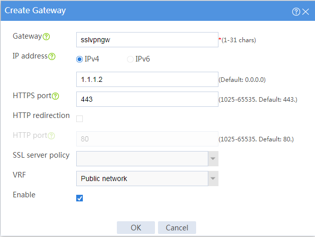
# Create an SSL VPN gateway as shown in Figure 2, and then click OK.
Figure 2 Creating an SSL VPN gateway
Configure an SSL VPN context:
# On the top navigation bar, click Network.
# From the navigation pane, select SSL VPN > SSL VPN Contexts.
# Click Create.
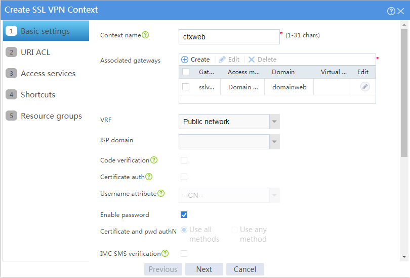
# Configure the basic settings for the SSL VPN context as shown in Figure 3, and then click Next.
Figure 3 Configuring basic settings for an SSL VPN context
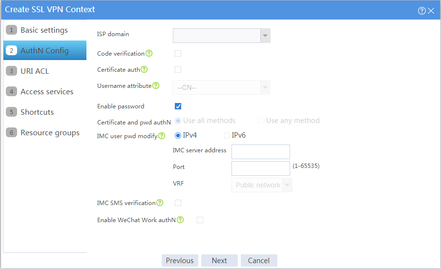
# Click Next to configure authentication settings, as shown in Figure 19.
Figure 4 Configuring authentication settings
# Click Next to open the URI ACL page. On the URI ACL page, click Next.
# On the Access services page, select Web access and click Next.
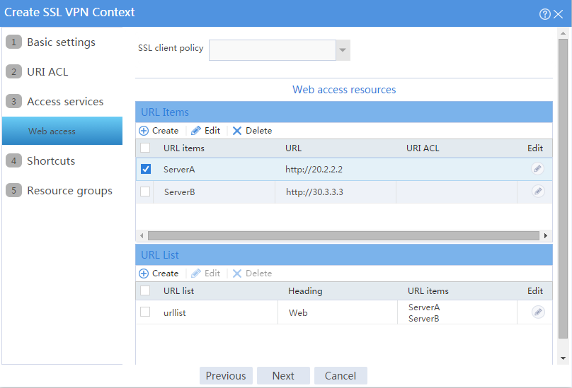
# On the Web access page, configure the Web access service as follows:
Configure two URL items pointing to Server A and Server B, respectively.
Add the two URL items to URL list urllist.
Click Next.
Figure 5 Configuring Web access service
# Click Next on the Shortcuts page.
# On the Resource groups page, click Create.
# Create a resource group named resourcegrp and select URL list urllist as the accessible Web resources, as shown in Figure 6.
Figure 6 Creating an SSL VPN resource group
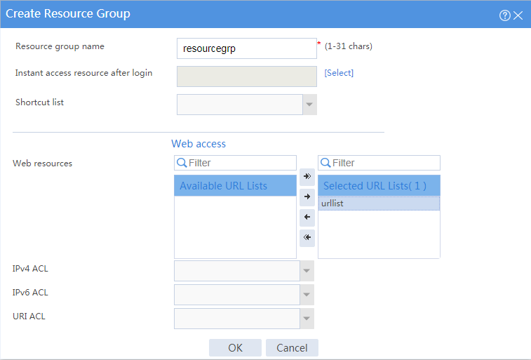
# Click OK.
The newly created resource group is displayed on the Resource groups page, as shown in Figure 7.
Figure 7 Resource groups configuration page
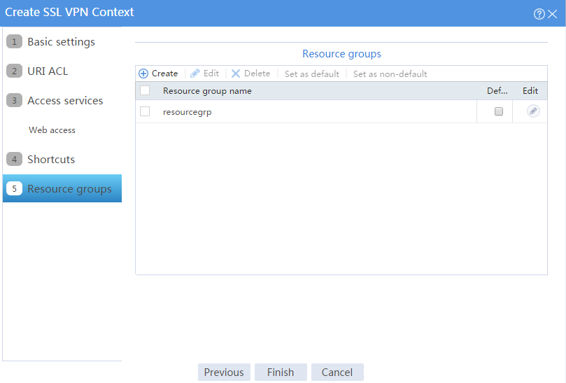
# Click Finish.
# Select the Enable check box to enable the SSL VPN context, as shown in Figure 8.
Figure 8 Enabling the SSL VPN context
![]()
Create an SSL VPN user:
# On the top navigation bar, click Objects.
# From the navigation pane, select User > User Management > Local Users.
# Click Create.
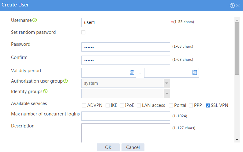
# Create an SSL VPN user:
Set the username to user1 and password to 123456, and select SSL VPN as the available service, as shown in Figure 9.
Figure 9 Creating an SSL VPN user
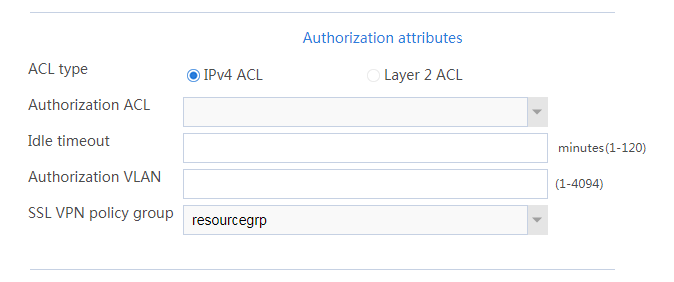
In the Authorization Attributes area, authorize the user to use SSL VPN resource group resourcegrp, as shown in Figure 10.
Figure 10 Setting the authorization attributes for the SSL VPN user
Click OK.
# Configure the IP address and gateway address settings for the host and make sure it can reach the SSL VPN gateway.
In the browser address bar of the host, enter https://1.1.1.2 and press Enter to open the domain list page.
Figure 11 Domain list page
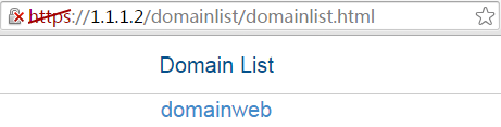
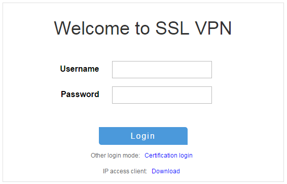
Select domainweb to access the login page.
On the login page, enter username user1 and password 123456, and then click Login.
Figure 12 Login page
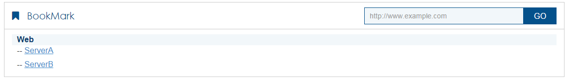
The SSL VPN home page opens, displaying the Web resources the user can access in the BookMark area.
Figure 13 Accessible Web resources
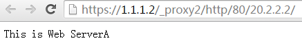
Click ServerA to access Web resources on Server A.
Figure 14 Accessing Server A
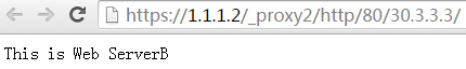
Click ServerB to access Web resources on Server B.
Figure 15 Accessing Server B