VRRP
This help contains the following topics:
Introduction
Virtual Router Redundancy Protocol (VRRP) adds a group of network gateways to a VRRP group called a virtual router. The VRRP group has one master and multiple backups, and provides a virtual IP address. The hosts on the subnet use the virtual IP address as their default network gateway to communicate with external networks.
VRRP avoids single points of failure and simplifies the configuration on hosts. When the master in the VRRP group on a multicast or broadcast LAN (for example, an Ethernet network) fails, another device in the VRRP group takes over. The switchover is complete without causing dynamic route recalculation, route re-discovery, gateway reconfiguration on the hosts, or traffic interruption.
VRRP group
VRRP adds a group of network gateways to a VRRP group called a virtual router. The VRRP group has one master and multiple backups.
VRRP and hot backup association
About VRRP and hot backup association
Figure-1 VRRP and hot backup association
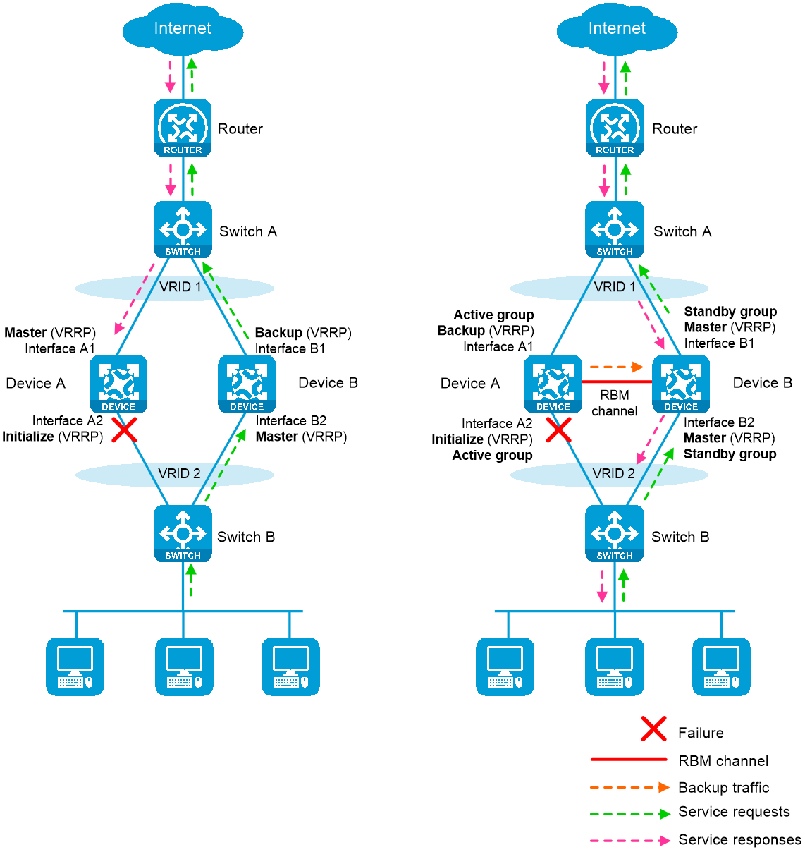
VRRP active/standby group
A VRRP active/standby group can be in master or backup state, which determines the state of devices in the associated VRRP groups. For example, if a VRRP active group is in master state, all devices in the associated VRRP groups are masters.
The initial state of a VRRP active/standby group varies by the device mode as follows:
Active/Standby mode —On the primary management device, the initial state is master for the VRRP active and standby groups. On the secondary management device, the initial state is backup for the VRRP active and standby groups.Dual-active mode —The state of a VRRP active/standby group is not affected by the primary and secondary management device roles. The initial state is master for the VRRP active group and is backup for the VRRP standby group.
VRRP master election in hot backup environment
In the network configured with VRRP and hot backup association as shown in
Typically, the VRRP active group state is master on Device A (suppose it is the primary management device), so Device A is the master in both VRRP group 1 and VRRP group 2. The VRRP standby group state is backup on Device B (suppose it is the secondary management device), so Device B is the backup in both VRRP group 1 and VRRP group 2.
When Interface A2 (downlink interface on Device A) fails, Device A receives an interface failure event. Device A then notifies Device B of the VRRP active/standby group state change event in an update packet, requesting Device B to change the VRRP standby group sate to master.
Upon receiving the update packet, Device B changes the VRRP standby group state to master. Meantime, Device B changes its state to master in VRRP group 1 and VRRP group 2. After the state change, Device B sends a reply to Device A.
Upon receiving the reply, Device A changes the VRRP active group state to backup. Meantime, Device A changes its state to backup in VRRP group 1 and VRRP group 2.
For traffic to switch back when Interface A2 recovers, the devices will perform another master/backup state switchover that is similar to the procedure described above.
Virtual IP address
A VRRP group provides a virtual IP address. The hosts on the subnet use the virtual IP address as their default network gateway to communicate with external networks.
The virtual IP address of the virtual router can be either of the following IP addresses:
Unused IP address on the subnet where the VRRP group resides.
IP address of an interface on a device in the VRRP group.
In the latter case, the router is called the IP address owner.
Device priority in a VRRP group
VRRP determines the role (master or backup) of each router in a VRRP group by priority. A router with higher priority is more likely to become the master.
A VRRP priority can be in the range of 0 to 255, and a greater number represents a higher priority. Priorities 1 to 254 are configurable. Priority 0 is reserved for special uses, and priority 255 is for the IP address owner. The IP address owner in a VRRP group always has a running priority of 255 and acts as the master as long as it operates correctly. A VRRP group can have only one IP address owner.
Preemption
A router in a VRRP group operates in either non-preemptive mode or preemptive mode.
Preemptive mode —A backup starts a new master election and takes over as master when it detects that it has a higher priority than the current master. Preemptive mode ensures that the router with the highest priority in a VRRP group always acts as the master.Non-preemptive mode —The master router acts as the master as long as it operates correctly, even if a backup router is later assigned a higher priority. Non-preemptive mode helps avoid frequent switchover between the master and backup routers.
You can configure the VRRP preemption delay timer for the following purposes:
Avoid frequent state changes among members in a VRRP group.
Provide the backups with enough time to collect information (such as routing information).
In preemptive mode, a backup does not immediately become the master after it receives an advertisement with priority lower than the local priority. Instead, it waits for a period of time before taking over as the master.
Preemption delay
In preemptive mode, upon receiving an advertisement with priority lower than the local priority, a backup waits for a period of time (preemption delay) before taking over as the master. If the preemption delay is 0, the backup immediately takes over as the master.
VRRP advertisement interval
The master in a VRRP group periodically sends VRRP advertisements to declare its presence.
As a best practice to maintain system stability, set the VRRP advertisement interval to be greater than 100 centiseconds.
In VRRPv2, all routers in an IPv4 VRRP group must have the same VRRP advertisement interval.
In VRRPv3, routers in a VRRP group can have different intervals for sending VRRP advertisements. The master in the VRRP group sends VRRP advertisements at specified intervals, and carries the interval in the advertisements. After a backup receives the advertisement, it records the interval in the advertisement. If the backup does not receive a VRRP advertisement before the timer (3 × recorded interval + Skew_Time) expires, it regards the master as failed and takes over.
A high volume of network traffic might cause a backup to fail to receive VRRP advertisements from the master within the specified time. As a result, an unexpected master switchover occurs. To solve this problem, configure a larger interval.
Authentication method
To avoid attacks from unauthorized users, VRRP members add authentication keys in VRRP packets to authenticate one another. VRRP provides the following authentication methods:
Simple authentication —The sender fills an authentication key into the VRRP packet, and the receiver compares the received authentication key with its local authentication key. If the two authentication keys match, the received VRRP packet is legitimate. Otherwise, the received packet is illegitimate and gets discarded.MD5 authentication —The sender computes a digest for the VRRP packet by using the authentication key and MD5 algorithm, and saves the result to the packet. The receiver performs the same operation with the authentication key and MD5 algorithm, and compares the result with the content in the authentication header. If the results match, the received VRRP packet is legitimate. Otherwise, the received packet is illegitimate and gets discarded.
On a secure network, you can choose to not authenticate VRRP packets.
VRRP control VLAN
By default, Layer 3 Ethernet subinterfaces on the master with ambiguous VLAN termination configured do not support sending broadcast packets or multicast packets. To allow the master to regularly send VRRP advertisements in multicast to the backups, enable the VLAN termination-enabled subinterfaces to transmit broadcast packets and multicast packets. Then, the master can send VRRP advertisements within all VLANs whose VLAN packets are configured to be terminated by the subinterfaces. If ambiguous VLAN termination is configured on the Layer 3 Ethernet subinterfaces for a large range of VLANs, the VRRP advertisements might overload the subinterfaces. This adversely affects the performance of the routers.
To resolve this problem, you can disable the VLAN termination-enabled subinterfaces from transmitting broadcast packets and multicast packets and configure a VRRP control VLAN. The master sends VRRP advertisements only within the control VLAN.
Specify VRRP control VLANs according to the VLAN termination type.
For ambiguous Dot1q termination, specify one control VLAN by the outermost layer of VLAN tag.
For ambiguous QinQ termination, specify two control VLANs by the outermost two layers of VLAN tags.
vSystem support information
Support of non-default vSystems for this feature depends on the device model. This feature is available on the Web interface only if it is supported.
Restrictions and guidelines
IPv4 VRRPv3 and IPv6 VRRPv3 do not support VRRP packet authentication.
You can configure different authentication modes and authentication keys for VRRP groups on an interface. However, members of the same VRRP group must use the same authentication mode and authentication key.
VRRP groups in load balancing mode do not support association with hot backup.
The VRRP group to be associated with hot backup cannot have IP address owners.
Configure VRRP
Complete the following tasks before you configure this feature:
Assign IP addresses to interfaces on the
Network >Interface Configuration >Interfaces page.Configure routes on the
Network >Routing page. Make sure the routes are available.Create security zones on the
Network >Security Zones page.Add interfaces to security zones. You can add interfaces to a security zone on the
Security Zones page or select a security zone for an interface on theInterfaces page.Configure security policies to permit the target traffic on the
Policies >Security Policies page.
Configure basic VRRP settings
Select
System >High Availability >VRRP .Click
Create to access the VRRP group creation pageFigure-2 Creating a VRRP group

Figure-3 VRRP group creation page
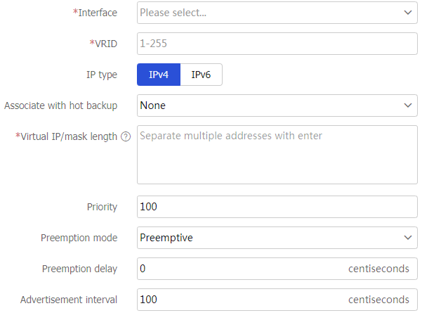
Configure a VRRP group as follows.
Table-1 Basic VRRP configuration items
Item
Description
Interface
Specify the interface to where the VRRP group resides.
VRID
Enter a virtual router ID that uniquely identifies a VRRP group. VRRP groups sharing the same VRID on different devices indicate one VRRP group.
IP type
Specify IPv4 or IPv6 VRRP.
Associate with hot backup
Configure this parameter in a VRRP-hot backup association scenario to enable collaboration between VRRP groups.
Virtual IP
Enter the virtual IP address of the VRRP group.
Priority
Enter the priority. A higher priority indicates the device is more likely to become the master of the VRRP group.
Preemption mode
Select the preemption mode: preemptive or non-preemptive.
Preemption delay
Enter the preemption delay time. A backup device waits for the specified period of time before it preempts as the master. 0 means the device immediately preempts as the master.
Advertisement interval
Set the VRRP packet advertisement interval.
For VRRPv2, the effective value can only be a multiple of 100. For example, if you configure the value as 10 through 100, 101 through 200, or 4001 through 4095, the effective value is 100, 200, or 4100, respectively.
For VRRPv3, the configured value takes effect.
Auth mode
Specify the no authentication, simple authentication, or MD5 authentication mode.
VRRP validates VRRP packets by adding an authentication key to prevent attacks with forged packets.
Click
OK .
Configure advanced VRRP settings
Select
System >High Availability >VRRP Advanced Settings .Click
Edit for the target interface to access the advanced VRRP settings page.Figure-4 Editing an interface

Figure-5 Advanced VRRP settings
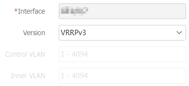
Configure advanced VRRP group settings.
Table-2 Advanced VRRP configuration items
Item
Description
Interface
Specify the interface to which the VRRP group is bound.
Version
Select VRRPv2 or VRRPv3. VRRPv2 supports only IPv4 VRRP. VRRPv3 supports both IPv4 VRRP and IPv6 VRRP.
All routers in an IPv4 VRRP group must use the same IPv4 VRRP version.
Control VLAN
Specify the control VLAN for a subinterface configured with ambiguous Dot1q termination.
Inner VLAN
Specify the inner VLAN for a subinterface configured with ambiguous QinQ termination.
Click
Apply to have the advanced VRRP group settings take effect.