IPv4 (NAT44)
This help contains the following topics:
Introduction
Network Address Translation (NAT) translates an IP address in the IP packet header to another IP address. Typically, NAT is configured on gateways to enable private hosts to access external networks and external hosts to access private network resources such as a Web server.
Dynamic NAT
Dynamic NAT uses an address pool to translate addresses. It applies to the scenario where a large number of internal users access the external network.
NO-PAT
Not Port Address Translation (NO-PAT) translates a private IP address to an IP public address. The public IP address cannot be used by another internal host until it is released.
NO-PAT supports all IP packets.
PAT
Port Address Translation (PAT) translates multiple private IP addresses to a single public IP address by mapping the private IP address and source port to the public IP address and a unique port. PAT supports TCP and UDP packets, and ICMP request packets.
A NAT address group is a set of address ranges. The source address in a packet destined for an external network is translated into an address in one of the address ranges.
NAT Server
The NAT Server feature maps a public address and port number to the private IP address and port number of an internal server. This feature allows servers in the private network to provide services for external users. The following table describes the address-port mappings between an external network and an internal network for NAT Server.
Table-1 Address-port mappings for NAT Server
External network | Internal network |
One public address | One private address |
One public address and one public port number | One private address and one private port number |
One public address and |
|
| |
| |
One public address and one public port number | One internal server group |
One public address and | |
Public addresses matching an ACL | One private address |
One private address and one private port | |
Public addresses in an address object group | One private address |
One private address and one private port |
You can add multiple internal servers to an internal server group for load sharing so that these servers provide the same service for external hosts. The NAT device chooses one internal server based on the weight and number of connections of the servers to respond to a request from an external host to the public address of the internal server group.
Static NAT
Static NAT creates a fixed mapping between a private address and a public address. It supports connections initiated from internal users to external network and from external users to the internal network. Static NAT applies to regular communications.
NAT444
NAT444 provides carrier-grade NAT by unifying the NAT444 gateway, AAA server, and log server. NAT444 introduces a second layer of NAT on the carrier side, with few changes on the customer side and the application server side. With port block assignment, NAT444 supports user tracking. It has become a preferred solution for carriers in transition to IPv6.
Figure-1
Figure-1 NAT444 solution architecture
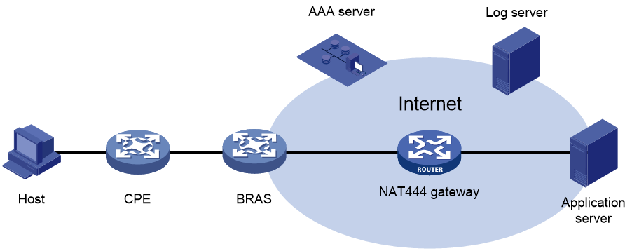
Devices in this architecture provide services as follows:
CPE —Performs customer-side address translation.BRAS —Provides endpoint access services and incorporates with the AAA server for authentication, authorization, and accounting.NAT444 gateway —Performs carrier-grade address translation.AAA server —Provides authentication, authorization, and accounting services.Log server —Records user access information and responds to user information queries.
NAT444 is a PAT translation based on port ranges. It maps multiple private IP addresses to one public IP address and uses a different port block for each private IP address. For example, the private IP address 10.1.1.1 of an internal host is mapped to the public IP address 202.1.1.1 and port block 10001 to 10256. When the internal host accesses public hosts, the source IP address 10.1.1.1 is translated to 202.1.1.1, and the source ports are translated to ports in the port block 10001 to 10256.
Static NAT444
The NAT gateway computes a static port block mapping before address translation. The mapping is between a private IP address and a public IP address with a port block.
When an internal user initiates a connection to the external network, the system performs the following operations:
Locates a static mapping based on the private IP address of the user and obtains the public IP address and the port block in the mapping.
Selects a public port number in the port block.
Translates the private IP address to the public IP address and assigns the selected public port number.
The NAT gateway uses private IP addresses, public IP addresses, a port range, and a port block size to compute static mappings:
Divides the port range by the port block size to get the number of available port blocks for each public IP address.
This value is the base number for mapping.
Sorts the port blocks in ascending order of the start port number in each block.
Sorts the private IP addresses and the public IP addresses separately in ascending order.
Maps the first base number of private IP addresses to the first public IP address and its port blocks in ascending order.
For example, the number of available port blocks of each public IP address is
Dynamic NAT444
Dynamic NAT444 integrates functionalities of dynamic NAT and static NAT444. When an internal user initiates a connection to the external network, the dynamic NAT444 operates as follows:
Uses ACLs to implement translation control. It processes only packets that match an ACL permit rule.
Creates a mapping from the internal user's private IP address to a public IP address and a port block.
Translates the private IP address to the public IP address, and the source ports to ports in the selected port block for subsequent connections from the private IP address.
Withdraws the port block and deletes the dynamic port block mapping when all connections from the private IP address are disconnected.
Dynamic port block mapping supports port block extending. If the ports in the port block for a private address are all occupied, dynamic port block mapping translates the source port to a port in an extended port block.
NAT advanced settings
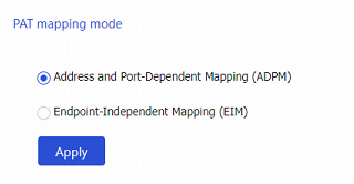
PAT mapping modes
The following PAT mapping modes are supported:
Endpoint-Independent Mapping (EIM) —Uses the same IP and port mapping (EIM entry) for packets from the same source IP and port to any destinations. EIM allows external hosts to initiate connections to the translated IP addresses and ports of internal hosts. It allows internal hosts behind different NAT gateways to access each other.Address and Port-Dependent Mapping (APDM) —Uses different IP and port mappings for packets from the same source IP and port to different destination IP addresses and ports. APDM allows an external host to initiate connections to an internal host only under the condition that the internal host has previously accessed the external host. It is secure, but it does not allow internal hosts behind different NAT gateways to access each other.
NAT DNS mappings
With NAT DNS mappings, a user in the internal network can access internal servers by using their domain names when the DNS server is located on the public network. The NAT DNS mapping works in conjunction with NAT server mappings. A NAT DNS mapping maps the domain name of an internal server to the public IP address, public port number, and protocol type of the internal server. A NAT server mapping maps the public IP and port to the private IP and port of the internal server.
The DNS reply from the external DNS server contains only the domain name and public IP address of the internal server in the payload. The NAT interface might have multiple NAT server mappings with the same public IP address but different private IP addresses. DNS ALG might find an incorrect internal server by using only the public IP address. If a NAT DNS mapping is configured, DNS ALG can obtain the public IP address, public port number, and protocol type of the internal server by using the domain name. Then it can find the correct internal server by using the public IP address, public port number, and protocol type of the internal server.
NAT hairpin
NAT hairpin allows internal hosts to access each other through NAT. The source and destination IP address of the packets are translated on the interface connected to the internal network. NAT hairpin works in conjunction with NAT Server and outbound dynamic or static NAT. To provide service correctly, you must configure NAT hairpin on the same interface module as its collaborative NAT feature.
NAT hairpin includes C/S and P2P modes:
C/S —Allows internal hosts to access internal servers through NAT addresses. The destination IP address of the packet going to the internal server is translated by matching the NAT Server configuration. The source IP address is translated by matching the outbound dynamic or static NAT entries.P2P —Allows internal hosts to access each other through NAT. The internal hosts first register their public addresses to an external server. Then, the hosts communicate with each other by using the registered IP addresses. To configure the P2P mode, you must configure outbound PAT on the interface connected to the external network and enable the EIM mapping mode.
NAT global settings
On a WAN network where two output interfaces of the NAT device are in the same security zone, if the link of one interface fails, traffic is switched to the link of the other interface. The NAT device retains old session entries after link switchover. Internal users cannot access the external network because the NAT device uses old session entries to match the user traffic. To avoid this issue, enable NAT session recreation to ensure availability of NAT services. The device will recreate NAT sessions when user traffic arrives.
vSystem support information
Support of non-default vSystems for this feature depends on the device model. This feature is available on the Web interface only if it is supported.
Restrictions and guidelines
General restrictions and guidelines
Policy NAT has higher priority than interface NAT for the traffic that matches both of them.
A NAT or NAT444 address group cannot be used by both PAT and NO-PAT modes.
As a best practice, configure inbound static NAT with outbound dynamic NAT, NAT Server, or outbound static NAT to implement bidirectional NAT.
If you perform all the translation methods on an interface, the NAT rules are sorted in the following descending order:
NAT Server.
Static NAT.
NAT444 static port block mapping.
Dynamic NAT.
When you add address ranges to a NAT address group, make sure address ranges do not overlap.
The number of IP addresses in all NAT address groups cannot be smaller than the number of security engines. Otherwise, some security engines cannot obtain NAT address resources.
Restrictions and guidelines: Dynamic NAT
You can configure multiple outbound dynamic NAT rules on an interface.
A NAT rule with an ACL takes precedence over a rule without any ACL.
If two ACL-based dynamic NAT rules are configured, the rule with the higher ACL number has higher priority.
Restrictions and guidelines: Static NAT
When you specify object groups for a static mapping, follow these restrictions and guidelines:
The public or private IPv4 address object group can contain only one IPv4 address object.
The quantity of IPv4 addresses in the private IPv4 address object group cannot be larger than that in the public IPv4 address object group.
The object in the public IPv4 address object group cannot be an address range.
An address object cannot have excluded addresses. Otherwise, the mapping does not take effect.
The modification to an address object group will directly take effect on the static NAT mapping that references the address object group.
You must specify a VRF if you deploy outbound static NAT in VPN networks. The specified VRF must be the VRF to which the NAT interface belongs.
When you specify an ACL, follow these restrictions and guidelines:
If you do not specify an ACL, the source addresses of all outgoing packets and the destination addresses of all incoming packets are translated.
If you specify an ACL and do not specify the reverse address translation, the source addresses of outgoing packets permitted by the ACL are translated. The destination addresses of packets are not translated for connections actively initiated by external hosts to the internal hosts.
If you specify both an ACL and the reverse address translation, the source addresses of outgoing packets permitted by the ACL are translated. If packets of connections actively initiated by external hosts to the internal hosts are permitted by ACL reverse matching, the destination addresses are translated. ACL reverse matching works as follows:
Compares the source IP address/port of a packet with the destination IP addresses/ports in the ACL.
Translates the destination IP address of the packet according to the mapping, and then compares the translated destination IP address/port with the source IP addresses/ports in the ACL.
Restrictions and guidelines: NAT Server
When you configure a load shared NAT server mapping, you must make sure a user uses the same public address and public port to access the same service on an internal server. For this purpose, make sure value
N in the following mappings is equal to or less than the number of servers in the internal server group:One public address and
N consecutive public port numbers are mapped to one internal server group.N consecutive public addresses and one public port number are mapped to one internal server group.
An internal server with a larger weight receives a larger percentage of connections in the internal server group.
You must specify a VRF if you configure NAT server mappings in VPN networks. The specified VRF must be the VRF to which the NAT interface belongs.
When you configure object group-based NAT server mappings, object groups for matching public addresses can only be IPv4 address object groups configured with subnets, IP address ranges, or host addresses. The IPv4 address object groups cannot have excluded IPv4 addresses.
Configure NAT
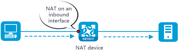
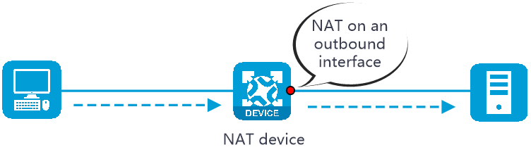
NAT can be performed in the inbound or outbound direction.
Inbound NAT —Performs address translation for packets received on an interface, as shown in Figure-2.Outbound NAT —Performs address translation for packets sent out of an interface, as shown in Figure-3.
Prerequisites
Complete the following tasks before you configure this feature:
Assign IP addresses to interfaces on the
Network >Interface Configuration >Interfaces page.Configure routes on the
Network >Routing page. Make sure the routes are available.Create security zones on the
Network >Security Zones page.Add interfaces to security zones. You can add interfaces to a security zone on the
Security Zones page or select a security zone for an interface on theInterfaces page.Configure security policies to permit the target traffic on the
Policies >Security Policies page.
Configure dynamic NAT
Dynamic NAT uses an address pool to translate addresses. It applies to the scenario where a large number of internal users access the external network.
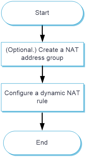
Only outbound dynamic NAT is supported in the current software version. You can configure ACL-based outbound dynamic NAT or object group-based outbound dynamic NAT. Figure-4
Figure-4 Dynamic NAT configuration procedure
Procedure
(Optional.) Create a NAT address group.
Click the
Objects tab.In the navigation pane, select
Object Groups >NAT Address Groups .Click
Create . For more information, see "Object groups."Click
Apply .
Configure ACL-based dynamic NAT.
Click the
Policies tab.In the navigation pane, select
Interface NAT >IPv4 .Click the
Outbound Dynamic NAT (ACL-Based) tab.Click
Create .Create an ACL-based outbound dynamic NAT rule, as shown in Table-2.
Figure-5 Clicking Create

Figure-6 Creating an ACL-based outbound dynamic NAT rule
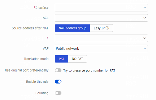
Table-2 Configuration items for ACL-based outbound dynamic NAT
Item
Description
Interface
Interface to which the NAT rule is applied. Outbound dynamic NAT is typically configured on the interface connected to the external network.
ACL
ACL for packet matching. If you specify an ACL, NAT translates the source IP addresses of outgoing packets permitted by the ACL. If you do not specify an ACL, NAT translates all packets.
Source address after NAT
Select the NAT address for address translation:
NAT address group —IP addresses in the NAT address group are used for address translation.Easy IP —The IP address of the specified interface is used for address translation.
An address group cannot be used by both PAT and NO-PAT modes.
VRF
VRF to which the source addresses belong after translation. The default setting is Public network.
You must specify this parameter if you deploy outbound dynamic NAT for VPNs. The specified VRF must be the VRF to which the specified interface belongs.
Translation mode
Dynamic NAT translation mode:
PAT—Uses the IP addresses in the address group or the IP address of the interface to translate IP addresses of the matching packets. Source ports in the matching packets are also translated.
NO-PAT—Uses the IP addresses in the address group to translate IP addresses of the matching packets. Source ports in the matching packets are not translated.
Use original port preferentially
Try to preserve port number for PAT.
This option is available only when the translation mode is set to PAT.
Allow reverse NAT
Enable reverse address translation. Reverse address translation uses existing NO-PAT entries to translate the destination address for connections actively initiated from the external network to the internal network.
This option is available only when the translation mode is set to NO-PAT.
Enable this rule
Enable this NAT rule.
Counting
Enable hit counting for the NAT rule. After you enable this feature, you can view the hit count of the NAT rule.
Click
Apply .
Configure object group-based dynamic NAT.
Click the
Policies tab.In the navigation pane, select
Interface NAT >IPv4 .Click the
Outbound Dynamic NAT (Object Group-Based) tab.Click
Create .Create an object group-based outbound dynamic NAT rule, as shown in Table-3.
Figure-7 Clicking Create

Figure-8 Creating an object group-based outbound dynamic NAT rule
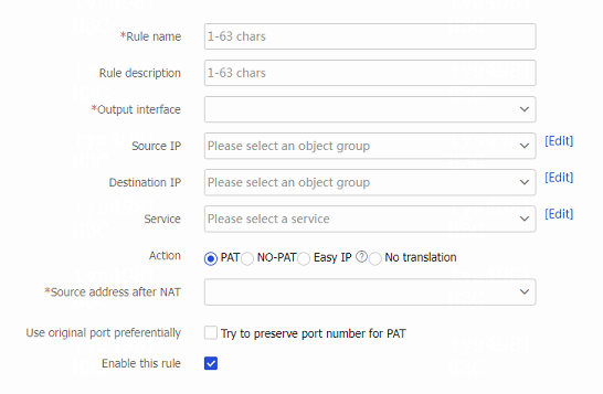
Table-3 Configuration items for object group-based outbound dynamic NAT
Item
Description
Rule name
Enter the name of a NAT rule.
Rule description
Enter the description of the NAT rule.
Output interface
Interface to which the NAT rule is applied. Outbound dynamic NAT is typically configured on the interface connected to the external network.
Source IP
Source IP address object group for the NAT rule.
You can configure multiple source IP address object groups for a NAT rule. Each source IP object group is an independent packet match criterion.
Destination IP
Destination IP address object group for the NAT rule.
You can configure multiple destination IP address object groups for a NAT rule. Each destination IP object group is an independent packet match criterion.
Service
Service object group for the NAT rule.
You can configure multiple service object groups for a NAT rule. Each service object group is an independent packet match criterion.
If you configure service object groups, source IP object groups, and destination object groups for a NAT rule, only packets with matching service type, source IP address, and destination IP address are translated.
Action
Dynamic NAT translation mode:
PAT —Uses the IP addresses in the address group or the IP address of the interface to translate IP addresses of the matching packets. Source ports in the matching packets are also translated.NO-PAT —Uses the IP addresses in the address group to translate IP addresses of the matching packets. Source ports in the matching packets are not translated.Easy IP —Uses the IP address of the specified interface for address translation.No translation —Does not translate matching packets.
Source address after NAT
NAT address group for source address translation.
An address group cannot be used by both PAT and NO-PAT modes.
Use original port preferentially
Try to preserve port number for PAT.
This option is available only when the translation mode is set to PAT or Easy IP.
Allow reverse NAT
Enable reverse address translation. Reverse address translation uses existing NO-PAT entries to translate the destination address for connections actively initiated from the external network to the internal network.
This option is available only when the translation mode is set to NO-PAT.
Enable this rule
Enable this NAT rule.
Click
Apply .
Configure NAT Server
The NAT Server feature maps a public address and port number to the private IP address and port number of an internal server. This feature allows servers in the private network to provide services for external users.
Procedure
Configure a NAT server rule.
Click the
Policies tab.In the navigation pane, select
Interface NAT IPv4 .Click the
NAT Servers tab.Click
Create .Create a NAT server rule, as shown in Table-4.
Figure-9 Clicking Create

Figure-10 Creating a NAT server rule
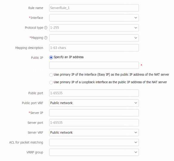

Table-4 NAT server configuration items
Item
Description
Rule name
Enter the name of a NAT server rule.
Interface
Interface to which the NAT server rule is applied. The NAT server rule is typically configured on the interface connected to the external network.
Protocol type
Specify a protocol type. If you do not specify a protocol type, the configuration applies to packets of all protocols.
Mapping
Select an address-port mapping. For more information, see Table-1.
Mapping description
Mapping description for identification when a large number of NAT mappings exist.
Public IP
Specify an IP address
Specify an IP address provided by the internal server for external network access.
Use primary IP of the interface (Easy IP) as the public IP address of the NAT server
Specify the IP address of the current interface as the public IP address of the internal server.
Use primary IP of a Loopback interface as the public IP address of the NAT server
Specify the IP address of a loopback interface as the public IP address of the server.
Public port
Public port number or port range, depending on the mapping method. When you specify a port range, make sure the end port is greater than the start port.
Public port VRF
VRF to which the advertised public IP addresses belong. The default setting is Public network.
Server IP
Private IP address or address range, depending on the mapping method. In the address range, the end address must be greater than the start address. The number of addresses in the range must equal the number of ports in the public port range.
Server port
Private port number or port range, depending on the mapping method. When you specify a port range, make sure the end port is higher than the start port.
Server VRF
VRF to which the NAT server belongs. The default setting is Public network.
ACL for packet matching
If you specify an ACL, NAT translates packets permitted by the ACL. If you do not specify an ACL, NAT translates all packets.
VRRP group
Specify a VRRP group for high availability purposes.
The master device in the VRRP group uses the virtual IP address and virtual MAC address to answer ARP requests.
Support for the VRRP group feature depends on the device model.
Allow reverse NAT
Allow reverse address translation. Reverse address translation applies to connections actively initiated by internal servers to the external network. It translates the private IP addresses of the internal servers to their public IP addresses.
This option is available only when the mapping type is set to One single public address with one single or no public port.
Enable this rule
Enable this NAT server rule.
Counting
Enable hit counting for the NAT server rule. After you enable this feature, you can view the hit count of the NAT server rule.
Click
Apply .
Configure static NAT
Static NAT creates a fixed mapping between a private address and a public address. It supports connections initiated from internal users to external network and from external users to the internal network.
Only outbound static NAT is supported in the current software version. Configure static NAT as shown in Figure-11.
Figure-11 Static NAT configuration procedure
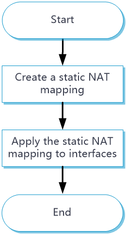
Procedure
Click the
Policies tab.In the navigation pane, select
Interface NAT IPv4 .Click the
Static NAT tab.Click
Create .Create a static NAT mapping.
Figure-12 Clicking
Create 
Figure-13 Creating a static NAT mapping
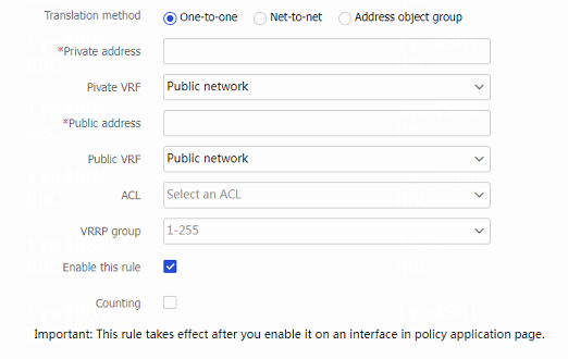
Table-5 Static NAT configuration items
Item
Description
Translation method
Select an address translation method:
One-to-one —Performs address translation from a private IP address to a public IP address.Net-to-net —Performs address translation from a private network to a public networkAddress object group —Performs address object group-based address translation.
Private address
Private IP address. The parameter setting depends on the translation method. If address object group-based translation method is selected, you must specify an IPv4 address object group.
Private VRF
VRF to which the private IP address belongs. The default setting is
Public network .Public address
Public IP address. The parameter setting depends on the translation method. If address object group-based translation method is selected, you must specify an IPv4 address object group.
Public VRF
VRF to which the public IP address belongs. The default setting is
Public network .ACL
Specify an ACL to define the destination IP addresses that internal hosts can access.
VRRP group
Specify a VRRP group for high availability purposes.
The master device in the VRRP group uses the virtual IP address and virtual MAC address to answer ARP requests.
Support for the VRRP group feature depends on the device model.
Allow reverse NAT
Allow reverse address translation. Reverse address translation applies to connections actively initiated by external hosts to the internal host. It uses the mapping to translate the destination address for packets of these connections if the packets are permitted by ACL reverse matching.
Enable this rule
Enable this static NAT rule.
Counting
Enable hit counting for the static NAT rule. After you enable this feature, you can view the hit count of the static NAT rule.
Click
Apply .Click
Policy Apply .Figure-14 Clicking Policy Apply

Figure-15 Policy application page
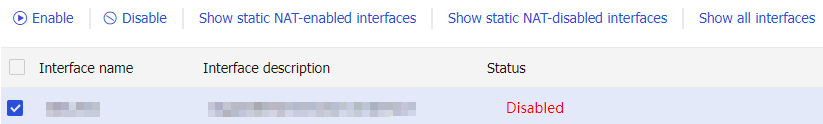
Select one or multiple interfaces.
Click
Enable .
Configure static NAT444
NAT444 provides carrier-grade NAT by unifying the NAT444 gateway, AAA server, and log server. It supports user tracking.
Configure static NAT444 as shown in Figure-16.
Figure-16 Static NAT444 configuration procedure
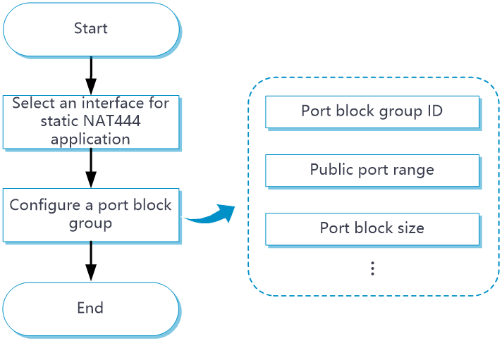
Procedure
Click the
Policies tab.In the navigation pane, select
Interface NAT >IPv4 .Click the
Static NAT444 tab.Click
Create .Figure-17 Clicking Create

Figure-18 Creating a static NAT444 mapping
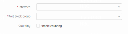
Select an interface.
Select or create a port block group.
(Optional.) Enable counting to view the hit count of the rule.
Click
Apply .
Configure advanced NAT settings
Configure NAT DNS mappings
With NAT DNS mappings, a user in the internal network can access internal servers by using their domain names when the DNS server is located on the public network.
Click the
Policies tab.In the navigation pane, select
Interface NAT >IPv4 .Click the
NAT DNS Mappings tab.Click
Create to add a new mapping entry for a domain name to the internal server.Figure-19 Clicking Create

Figure-20 Creating a NAT DNS mapping
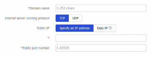
Table-6 NAT DNS mapping configuration items
Item
Description
Domain name
Specify a domain name for the internal server.
Internal server running protocol
Select a running protocol for the internal server:
TCP .UDP .
Public IP
Specify an IP address
Specify an IP address provided by the internal server for external network access.
Easy IP
Specify the IP address of a loopback interface as the public IP address of the internal server.
Public port number
Specify a public port number for the internal server.
Click
Apply .
Configure NAT Hairpin
Enable NAT hairpin on the interface connected to the internal network to allow internal hosts to access each other through NAT.
Click the
Policies tab.In the navigation pane, select
Interface NAT >IPv4 .Click the
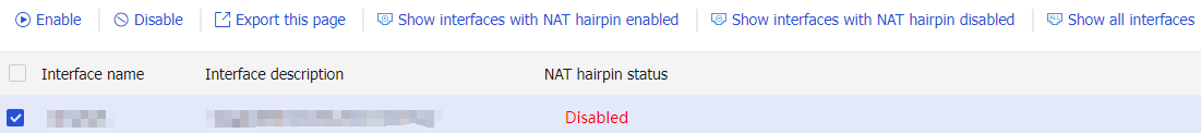
NAT Hairpin tab.Select an interface.
Click
Enable to enable NAT Hairpin on the selected interface.Figure-21 Enabling NAT hairpin on the selected interface
Configure general settings
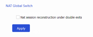
On a WAN network where two output interfaces of the NAT device are in the same security zone, if the link of one interface fails, traffic is switched to the link of the other interface. The NAT device retains old session entries after link switchover. Internal users cannot access the external network because the NAT device uses old session entries to match the user traffic. To avoid this issue, enable NAT session recreation to ensure availability of NAT services. The device will recreate NAT sessions when user traffic arrives.
Click the
Policies tab.In the navigation pane, select
Interface NAT >IPv4 .Click the
General Settings tab.Select
Nat session reconstruction under double exis ts .Click
Apply .Figure-22 Enabling NAT session recreation
Configure PAT mode
Click the
Policies tab.In the navigation pane, select
Interface NAT >IPv4 .Click the
General Settings tab.Select a PAT mapping mode. Options include
Address and Port-Dependent Mapping (APDM) andEndpoint-Independent Mapping (EIM) .Click
Apply .Figure-23 Selecting a PAT mapping mode