Server load balancing
This help contains the following topics:
Introduction
Server load balancing is a cluster technology that distributes services among multiple servers or firewalls.
Load balancing types
Server load balancing is classified into Layer 4 server load balancing and Layer 7 server load balancing.
Layer 4 server load balancing —Identifies network layer and transport layer information, and is implemented based on streams. It distributes packets in the same stream to the same server. Layer 4 server load balancing cannot distribute Layer 7 services based on contents.Layer 7 server load balancing —Identifies network layer, transport layer, and application layer information, and is implemented based on contents. It analyzes packet contents, distributes packets one by one based on the contents, and distributes connections to the specified server according to the predefined policies. Layer 7 server load balancing applies load balancing services to a large scope.
Deployment modes
Server load balancing supports the gateway, indirect, and triangle deployment modes.
Gateway mode
In the gateway mode, the LB device is directly connected to the real servers and processes both of the requests and responses. When the LB device receives a user request, it uses the predefined health monitoring, sticky method, LB policy, and scheduling algorithm settings to calculate a real server for distributing the request. Then, the LB device sets the destination IP address of the request to the IP address of the calculated real server. When the LB device receives a response from the real server, it sets the source IP address to the VSIP.
Gateway-mode LB requires you to configure the default gateway or a static route for the real server. The real server can then send packets destined to the user through the LB device.
The gateway mode typically applies to small networks, because the deployment of the LB device changes the network topology.
Figure-1 Gateway-mode LB deployment
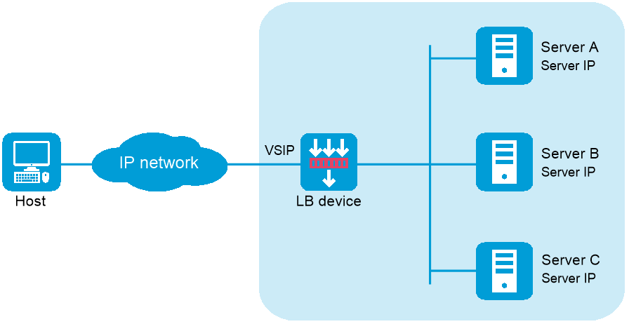
NAT-mode server load balancing contains the following elements:
LB device —Distributes different service requests to multiple servers.Server —Responds to and processes different service requests.VSIP —Virtual service IP address of the cluster, used for users to request services.Server IP —IP address of a server, used by the LB device to distribute requests.
Indirect mode
In the indirect mode, the LB device is attached to the core switch and processes both of the requests and responses.
When the LB device receives a user request, it uses the predefined health monitoring, sticky method, LB policy, and scheduling algorithm settings to calculate a real server for distributing the request. Then, the LB device sets the destination IP address of the request to the IP address of the calculated real server. When the SLB device receives a response from the real server, it sets the source IP address to the VSIP.
Indirect-mode LB requires you to configure the default gateway or a static route for the real server. The real server can then send packets destined to the user through the core switch to which the LB device is attached.
The indirect mode is more flexible, because the LB device deployment does not change the network topology.
Figure-2 Indirect-mode LB deployment
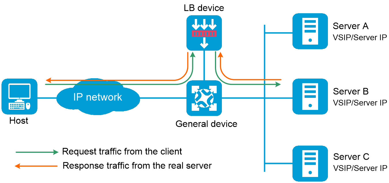
Indirect-mode server load balancing contains the following elements:
LB device —Distributes different service requests to multiple servers.General device —Forwards data according to general forwarding rules.Server —Responds to and processes different service requests.VSIP —Virtual service IP address of the cluster, used for users to request services.Server IP —IP address of a server, used by the LB device to distribute requests.
Indirect-mode server load balancing requires configuring the VSIP on both the LB device and the servers. Because the VSIP on a server cannot be contained in an ARP request and response, you can configure the VSIP on a loopback interface.
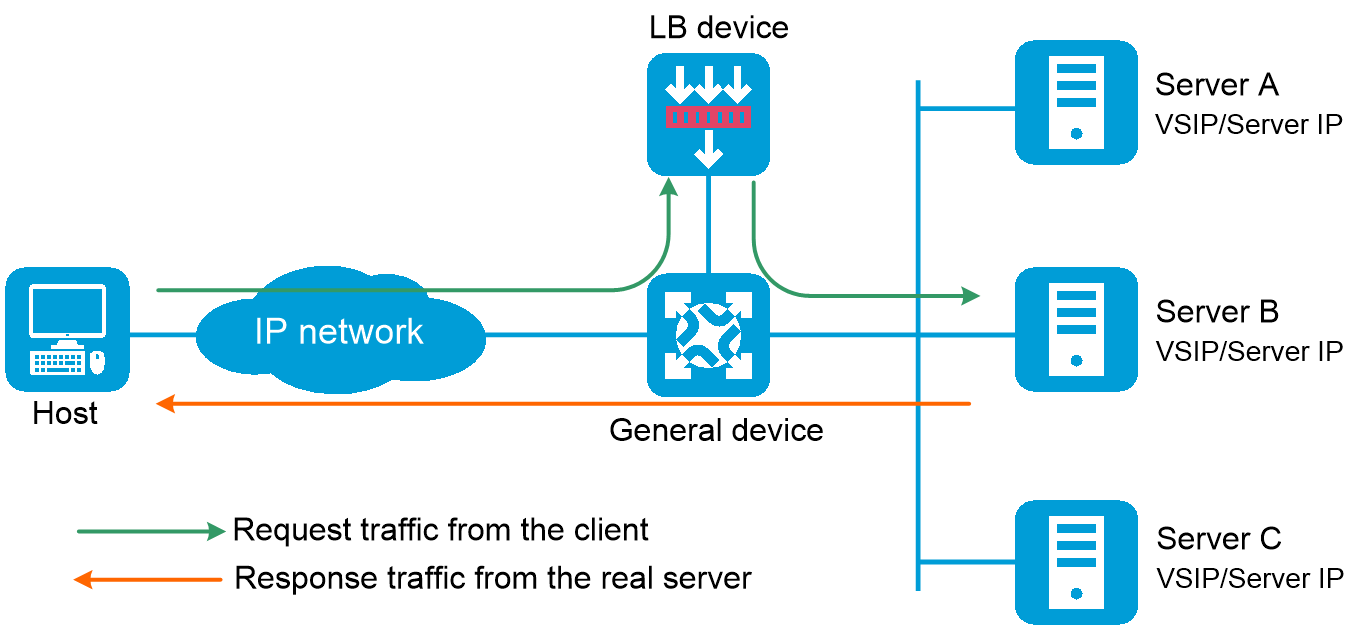
Triangle mode
In the triangle mode, the LB device is attached to the core switch and processes only user requests. The LB device does not process the responses from the real servers. When the LB device receives a request from the user, it uses the predefined health monitoring, sticky method, LB policy, and scheduling algorithm settings to calculate a real server for distributing the request. Then, the LB device distributes the request to the calculated real server, with the VSIP as the destination IP address but the MAC address of the real server as the destination MAC address. When the real server receives the request, it processes the request and sends a response directly to the user, with the VSIP as the source IP address and the user's IP address as the destination IP address.
Triangle-mode LB requires configuring the default gateway or a static route for the real server to send packets destined to the user through the gateway. In addition, you must configure the VSIP for the loopback interface on each real server.
The triangle mode is flexible, because the LB device deployment does not change the network topology. It typically applies to the scenarios with heavy traffic, such as video services, because the response traffic does not go through the LB device.
Figure-3 Triangle-mode LB deployment
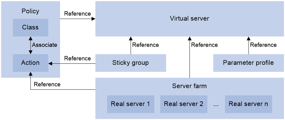
Relationship between the main configuration items
Figure-4 Relationship between the main configuration items
vSystem support information
Support of non-default vSystems for this feature depends on the device model. This feature is available on the Web interface only if it is supported.
Restrictions and guidelines
Server load balancing supports IPv4 and IPv6, but Layer 4 server load balancing does not support IPv4-to-IPv6 or IPv6-to-IPv4 translation.
Do not specify the same VSIP and port number for virtual servers of the UDP and SIP-UDP types; do not specify the same VSIP and port number for virtual servers of the TCP, SIP-TCP, HTTP, HTTPS, HTTP redirection, RADIUS, MySQL, and Diameter types.
Licensing requirements
To configure server load balancing, you must purchase and install the required license. For more information about licensing, see the license management help.
Configure server load balancing
Analysis
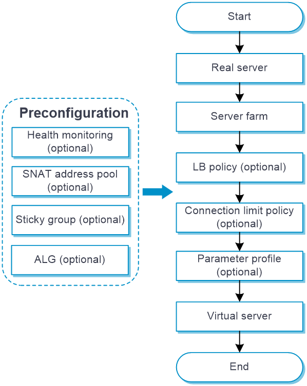
Configure server load balancing as shown in Figure-5
Figure-5 Server load balancing configuration procedure
Prerequisites
Complete the following tasks before you configure this feature:
Assign IP addresses to interfaces on the
Network >Interface Configuration >Interfaces page.Configure routes on the
Network >Routing page. Make sure the routes are available.Create security zones on the
Network >Security Zones page.Add interfaces to security zones. You can add interfaces to a security zone on the
Security Zones page or select a security zone for an interface on theInterfaces page.Configure security policies to permit the target traffic on the
Policies >Security Policies page.(Optional.) Configure health monitoring on the
Object >Load Balancing >Health Monitoring page. You can specify a health monitoring probe template for a real server or server farm.(Optional.) Configure SNAT pools on the
Object >Load Balancing >SNAT Pools page. You can specify an SNAT pool for a server farm.(Optional.) Configure sticky groups on the
Object >Load Balancing >Session Persistence page. You can specify a sticky group for a virtual server or LB action.(Optional.) Configure ALG on the
Network >ALG page.
Quick configuration
The quick configuration page facilitates server load balancing configuration by guiding you through the key steps of virtual server configuration.
To perform quick configuration:
Select
LB >Application Load Balancing >Quick Configuration .Figure-6 Quick configuration for server load balancing settings
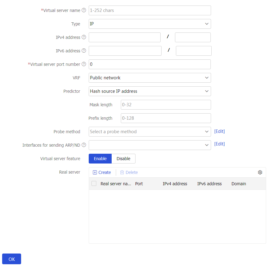
Click
OK . The configured virtual server will be displayed on the virtual server page.
Configure a virtual server
A virtual server is a virtual service provided by the LB device to determine whether to perform load balancing for packets received on the LB device. Only the packets that match a virtual server are load balanced.
To configure a virtual server:
Select
Polic ies >LB Policy >Server Load Balancing >Virtual Servers .Click
Create .Create a virtual server and configure basic virtual server settings.
Figure-7 Basic virtual server settings
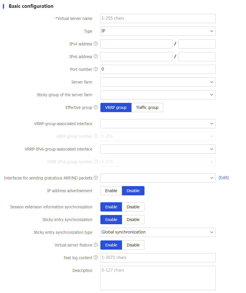
Table-1 Basic configuration items
Item
Description
Virtual server name
Enter a name for the virtual server, case insensitive.
Type
Specify the virtual server type, which can be IP, TCP, UDP, SIP-TCP, SIP-UDP, HTTP, HTTPS, HTTP redirection, RADIUS, MySQL, or Diameter.
IPv4 address
Configure an IPv4 address/mask length (0-32) for the virtual server.
IPv6 address
Configure an IPv6 address/prefix length (0-128) for the virtual server.
Port number
Configure the port number of the virtual server. 0 indicates any port.
For the IP, TCP, UDP, and RADIUS virtual server types, you can enter a comma-separated list of up to 32 port number items. Each item specifies a port number or a range of port numbers, for example, 5,10,20-28.
UDP per-packet load balancing
Enable or disable per-packet load balancing for UDP traffic for a virtual server.
When per-packet load balancing for UDP traffic is disabled, the LB device distributes traffic matching the virtual server according to application type. Traffic of the same application type is distributed to one real server. When per-packet load balancing for UDP traffic is enabled, the LB device distributes traffic matching the virtual server on a per-packet basis.
This parameter is supported only by virtual servers of the UDP type, SIP-UDP type, and RADIUS type.
SSL server policy
Specify an SSL server policy for a virtual server to encrypt traffic between the LB device (SSL server) and the SSL client.
You can select an existing SSL server policy or create an SSL server policy.
This parameter is supported only by virtual servers of the TCP, HTTPS, and Diameter types.
Redirection URL
Specify a redirection URL for the virtual server, case sensitive. The redirection feature redirects all request packets matching the virtual server to the URL.
You can also specify the question mark (?) or the following character strings as the redirection URL:
%h: Specifies the host name in the client request packet.
%p: Specifies the URL in the client request packet.
%%: Specifies the percentage sign (%).
This parameter is supported only by virtual servers of the HTTP redirection type.
Redirection mode
Specify a redirection mode for the virtual server.
Temporary-302
Temporary-307
Permanent-301
This parameter is supported only by virtual servers of the HTTP redirection type.
Server farm
Select an existing server farm or create a server farm for the virtual server.
This parameter is not supported by virtual servers of the HTTP redirection or Diameter type.
Sticky group of the server farm
Select an existing sticky group or create a sticky group as the primary sticky group for the server farm.
This parameter is not supported by virtual servers of the HTTP redirection or Diameter type.
VRRP-group-associated interface
Specify the interface to be associated with the VRRP group.
If you configure this parameter, you must bind a VRRP group number to the virtual server.
VRRP group number
Specify the number of the VRRP group to be bound to the virtual server.
In a dual-active-mode hot backup system, both devices back up each other and process services. If you do not bind a VRRP group number to the virtual server, both devices process services and use the SNAT address pool. If you bind a VRRP group number to the virtual server, only the primary device processes services and uses the SNAT address pool. For more information about the hot backup system, see its online help.
You can configure this parameter only after you specify a VRRP-group-associated interface.
VRRP-IPv6-group-associated interface
Specify the interface to be associated with the IPv6 VRRP group.
If you configure this parameter, you must bind an IPv6 VRRP group number to the virtual server.
VRRP IPv6 group number
Specify the number of the IPv6 VRRP group to be bound to the virtual server.
In a dual-active-mode hot backup system , both devices back up each other and process services. If you do not bind an IPv6 VRRP group number to the virtual server, both devices process services and use the SNAT address pool. If you bind an IPv6 VRRP group number to the virtual server, only the primary device processes services and uses the SNAT address pool. For more information about the hot backup system, see its online help.
This setting applies only to virtual servers with IPv6 addresses.
You can configure this parameter only after you specify an VRRP-IPv6-group-associated interface.
MySQL version
Specify the MySQL database version.
The LB device initiates authentication to clients on behalf of the MySQL server and sends database initialization packets of the specified MySQL version to clients.
This parameter is supported only by MySQL virtual servers.
Read/Write splitting
Enable or disable read/write splitting.
This feature allows read commands and write commands to be executed by the read server farm and write server farm, respectively.
This feature helps reduce the impact of concurrent read/write requests on database performance.
After this feature is enabled, you must configure both a read server farm and a write server farm.
This parameter is supported only by MySQL virtual servers.
Read server farm
Select an existing server farm or create a server farm as the read server farm for the virtual server.
This parameter is available only when read/write splitting is enabled.
Read sticky group
Select an existing sticky group or create a sticky group as the read sticky group for the virtual server.
This parameter is available only when read/write splitting is enabled.
Write server farm
Select an existing server farm or create a server farm as the write server farm for the virtual server.
This parameter is available only when write/write splitting is enabled.
Write sticky group
Select an existing sticky group or create a sticky group as the write sticky group for the virtual server.
This parameter is available only when write/write splitting is enabled.
Interfaces for sending gratuitous ARP/ND packets
Specify interfaces for sending gratuitous ARP packets and ND packets.
If the IP address of an interface connected to a client is in the same network segment as the virtual server IP address, you must perform the following tasks:
Specify the interface connected to the corresponding client as an interface for sending gratuitous ARP/ND packets.
Enable IP address advertisement.
Operation mode
Operating mode of the virtual server:
Layer 4.
Layer 7.
This parameter is supported only by TCP virtual servers.
If you configure a TCP virtual server to operate at Layer 7, you must also specify a non-zero port number or a range of port numbers for the TCP virtual server.
Enable proxy protocol
After you enable the proxy protocol for the TCP virtual server, the device transparently transmits the actual source IP addresses to the real servers.
To avoid connection failures, make sure the real servers support the proxy protocol of the specified version before you enable it.
This parameter is available only for TCP virtual servers with the operation mode of Layer 7.
IP address advertisement
Enable or disable IP address advertisement for the virtual server.
After this feature is configured, the device advertises the IP address of the virtual server to OSPF for route calculation. When the service of a data center switches to another data center, the traffic to the virtual server can also be switched to that data center.
Redundancy group traffic distribution
Select an existing redundancy group or create a redundancy group. The traffic matching the virtual server is directed to the specified redundancy group.
If the redundancy group does not exist or contains no effective failover groups, this function does not take effect.
Support for this function depends on the device model.
Session extension information synchronization
Enable or disable session extension information synchronization for the virtual server.
This parameter is supported only by virtual servers of the IP, TCP, UDP, SIP-TCP, SIP-UDP, and RADIUS types.
Sticky entry synchronization
Enable or disable sticky entry synchronization for the virtual server.
The following configuration changes will cause the device to delete existing sticky entries and generate new ones based on subsequent traffic:
Disable sticky entry synchronization.
Change the sticky entry synchronization type.
Virtual servers of the HTTP redirection type do not support this function.
Sticky entry synchronization type
Select the sticky entry synchronization type:
Intra-group synchronization —Synchronizes sticky entries to the device in the same failover group.Global synchronization —Synchronizes sticky entries to devices in all failover groups.
This function is available only when sticky entry synchronization is enabled.
Virtual servers of the HTTP redirection type do not support this function.
Support for this function depends on the device model.
Virtual server feature
Enable or disable the virtual server.
After you configure a virtual server, you must enable the virtual server for it to work.
Reset connection
Enable or disable resetting connections upon virtual server unavailability.
With this feature enabled, the device immediately responds with an RST packet upon receiving a SYN packet and tears down the connection if the virtual server is unavailable.
This parameter is available only for virtual servers of the TCP, SIP-TCP, HTTP, and HTTPS types.
Fast log output
Configure the content to be output by using the fast log output feature.
Multiple semicolon-separated variables are supported, for example, %{host};%{is};%{ps}.
This parameter is supported only by IP, TCP, UDP, HTTP and HTTPS virtual servers.
For information about the supported variables, see "Appendix Fast log output content
." Description
Enter a description for the virtual server.
User list
Configure the user name and password used to log in to the MySQL server.
Click
Create to create a user.Username: Enter a username.
Password: Enter a password.
Click
OK . The new user appears in the user list.
The device supports a maximum of 100 login users.
This parameter is supported only by MySQL virtual servers.
(Optional.) Configure advanced virtual server settings.
Figure-8 Advanced virtual server settings
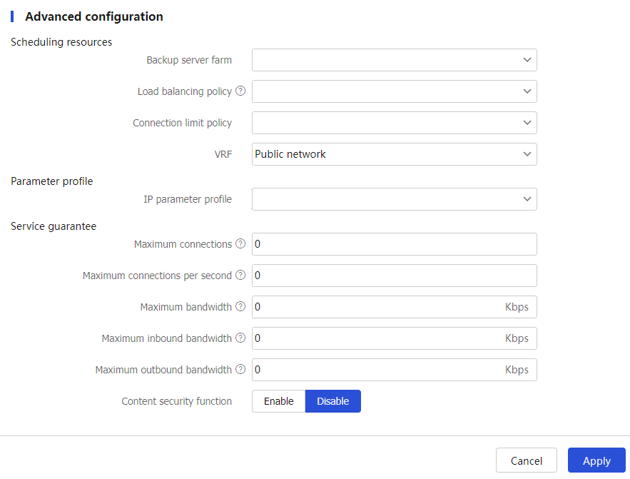
Table-2 Advanced configuration items
Item
Description
Insert X-Forwarded-For
Enable or disable source IP address insertion into the X-Forwarded-For field of the HTTP headers.
With this feature enabled, the device inserts the client source IP address into the X-Forwarded-For field of the HTTP headers when receiving a request from the client.
This parameter is supported only by virtual servers of the HTTP and HTTPS types.
Scheduling resources-Backup server farm
Specify the backup server farm for the virtual server.
When the primary server farm is available (contains real servers), the virtual server forwards packets through the primary server farm. When the primary server farm is not available, the virtual server forwards packets through the backup server farm.
You can select an existing server farm or create a server farm.
This parameter is not supported by virtual servers of the Diameter type.
Scheduling resources-Backup sticky group of the server farm
Specify the backup sticky group for the server farm.
If you specify both a primary sticky group and a backup sticky group, the device generates both primary sticky entries and backup sticky entries. If packets do not match primary sticky entries, backup sticky entries are used to match the packets.
This parameter is supported only by virtual servers of the HTTP, HTTPS, and RADIUS types.
Scheduling resources-Load balancing policy
Specify an LB policy for the virtual server.
By using an LB policy, the virtual server implements load balancing for matching packets based on the packet contents.
You can select an existing LB policy or create an LB policy.
A virtual server can use the policy template of the specified type. For example, a virtual server of the HTTP type can use a policy template of the generic type or HTTP type. A virtual server of the IP, TCP, UDP, SIP-TCP, or SIP-UDP type can use a policy template of the generic type only. A virtual server of the RADIUS type can use a policy template of the generic or RADIUS type only. A virtual server of the Diameter type can use a policy template of the Diameter type only.
Virtual servers of the HTTP redirection type do not support this function.
Scheduling resources-Connection limit policy
Specify a connection limit policy for the virtual server to limit the number of connections on the virtual server.
You can select an existing connection limit policy or create a connection limit policy.
Virtual servers of the HTTP redirection type do not support this function.
Scheduling resources-Cache policy
Specify a cache policy for the virtual server.
You can select an existing cache policy or create a cache policy.
This parameter is supported only by virtual servers of the HTTP and HTTPS types.
Scheduling resources-SSL client policy
Specify an SSL client policy for the virtual server to encrypt traffic between the LB device (SSL client) and the SSL server.
You can select an existing SSL client policy or create an SSL client policy.
This parameter is supported only by virtual servers of the HTTP or HTTPS type.
Scheduling resources-SSL server policy with SNI
Configure an SSL server policy with an SNI for the virtual server.
Click
Add to create an SSL server policy with an SNI.Policy name: Enter a policy name, case insensitive.
Server name indication (SNI): Enter an SNI, case insensitive.
Click
OK . The new SSL server policy appears in the policy list.
If you configured both an SSL server policy without an SNI and an SSL server policy with an SNI, the SSL server policy with an SNI takes effect.
You cannot configure multiple SSL server policies with the same SNI for a virtual server.
This parameter is supported only by virtual servers of the HTTPS type.
Scheduling resources-Cookie sticky group
Specify a cookie sticky group for the virtual server.
You can also specify sticky groups to be associated with server farms on the
Create Virtual Server page orCreate Action page. The cookie sticky group specified for the virtual server has the highest priority. It is preferentially used to generate sticky entries.Only cookie sticky groups can be specified for this parameter.
Cookie sticky groups with the cookie get sticky method cannot be specified for this parameter.
This parameter is supported only by virtual servers of the HTTP and HTTPS types.
Scheduling resources-VPN instance
Specify a VPN instance for the virtual server.
You can select an existing VPN instance or create a VPN instance.
Protection policy-HTTP protection policy
Specify an HTTP protection policy for the virtual server to guard against attack traffic matching the protection policy.
You can select an existing HTTP protection policy or create an HTTP protection policy.
This parameter is supported only by virtual servers of the HTTP and HTTPS types.
Parameter profile-IP parameter profile
Specify an IP parameter profile for the virtual server to process matching traffic based on the parameter profile.
You can select an existing IP parameter profile or create an IP parameter profile.
Virtual servers of the HTTP redirection type do not support this function.
Parameter profile-TCP parameter profile
Specify a TCP parameter profile for the virtual server to process and optimize matching traffic based on the parameter profile.
You can select an existing TCP parameter profile or create a TCP parameter profile.
This parameter is supported only by TCP virtual servers with the operation mode of Layer 4.
Parameter profile-TCP parameter profile (client side)
Specify a TCP parameter profile for the virtual server to process matching traffic based on the parameter profile. A TCP parameter profile (client) used by the virtual server processes and optimizes TCP connections between the device and the client.
You can select an existing TCP parameter profile or create a TCP parameter profile.
This parameter is supported only by HTTP, HTTPS, MySQL, Diameter virtual servers, and TCP virtual servers with the operation mode of Layer 7.
Parameter profile-TCP parameter profile (server side)
Specify a TCP parameter profile for the virtual server to process matching traffic based on the parameter profile. A TCP parameter profile (server) used by the virtual server processes and optimizes TCP connections between the device and the server.
You can select an existing TCP parameter profile or create a TCP parameter profile.
This parameter is supported only by HTTP, HTTPS, MySQL virtual servers, and TCP virtual servers with the operation mode of Layer 7.
Parameter profile-TCP-application parameter profile
Specify a TCP-application parameter profile for the virtual server to process matching traffic based on the parameter profile.
You can select an existing TCP-application parameter profile or create a TCP-application parameter profile.
This parameter is supported only by TCP virtual servers operating at Layer 7.
Parameter profile-HTTP parameter profile
Specify an HTTP parameter profile for the virtual server to process matching traffic based on the parameter profile.
You can select an existing HTTP parameter profile or create an HTTP parameter profile.
This parameter is supported only by virtual servers of the HTTP, or HTTPS type.
Parameter profile-HTTP2 parameter profile (client side)
Specify an HTTP/2 parameter profile on the client side for the virtual server. The device processes and optimizes HTTP/2 packets from the clients based on the specified parameter profile and sends HTTP/1.0 or HTTP/1.1 packets to the real servers.
You can select an existing HTTP/2 parameter profile or create an HTTP/2 parameter profile.
This parameter is supported only by virtual servers of the HTTP and HTTPS types.
Parameter profile-HTTP2 parameter profile (server side)
Specify an HTTP/2 parameter profile on the server side for the virtual server. After you specify HTTP/2 parameter profiles on both the client and server sides, the device processes and optimizes HTTP/2 packets from the clients based on the specified parameter profile and sends HTTP/2 packets to the real servers. If you specify an HTTP/2 parameter profile only on the server side but not on the client side for the virtual server, the specified parameter profile does not take effect.
You can select an existing HTTP/2 parameter profile or create an HTTP/2 parameter profile.
This parameter is supported only by virtual servers of the HTTP and HTTPS types.
Parameter profile-HTTP statistics parameter profile
Specify an HTTP statistics parameter profile for the virtual server to process matching traffic based on the parameter profile.
You can select an existing HTTP statistics parameter profile or create an HTTP statistics parameter profile.
This parameter is supported only by virtual servers of the HTTP or HTTPS type.
Parameter profile-HTTP compression parameter profile
Specify an HTTP compression parameter profile for the virtual server to process matching traffic based on the parameter profile.
You can select an existing HTTP compression parameter profile or create an HTTP compression parameter profile.
This parameter is supported only by virtual servers of the HTTP or HTTPS type.
Parameter profile-OneConnect parameter profile
Specify a OneConnect parameter profile for the virtual server to process matching traffic based on the parameter profile.
You can select an existing OneConnect parameter profile or create a OneConnect parameter profile.
This parameter is supported only by virtual servers of the HTTP or HTTPS type.
Parameter profile-MySQL parameter profile
Specify a MySQL parameter profile for the virtual server to process matching traffic based on the parameter profile.
You can select an existing MySQL parameter profile or create a MySQL parameter profile.
This parameter is supported only by virtual servers of the MySQL type.
Parameter profile-Diameter-Session parameter profile
Specify a Diameter-Session parameter profile for the virtual server to process matching traffic based on the parameter profile.
You can select an existing Diameter-Session parameter profile or create a Diameter-Session parameter profile.
This parameter is supported only by virtual servers of the Diameter type.
QoS-Maximum connections
Specify the maximum number of connections for the virtual server. 0 means not limited.
Virtual servers of the HTTP redirection type do not support this function.
QoS-Maximum connections per second
Specify the maximum number of connections per second for the virtual server. 0 means not limited.
Virtual servers of the HTTP redirection type do not support this function.
QoS-Maximum bandwidth
Specify the maximum bandwidth for the virtual server. 0 means not limited.
Virtual servers of the HTTP redirection or Diameter type do not support this function.
QoS-Maximum inbound bandwidth
Specify the maximum inbound bandwidth for the virtual server. 0 means not limited.
Virtual servers of the HTTP redirection or Diameter type do not support this function.
QoS-Maximum outbound bandwidth
Specify the maximum outbound bandwidth for the virtual server. 0 means not limited.
Virtual servers of the HTTP redirection or Diameter type do not support this function.
External link domain name rewrite
Enable or disable external link proxy.
The external link proxy feature enables an LB device to operate as an external link proxy to request IPv4 resources on behalf of IPv6 clients. This feature helps achieve smooth IPv4-to-IPv6 network transition.
This parameter is supported only by HTTP virtual servers.
When the LB device detects an external link in the HTTP response from the server, it returns a script file for rewriting the external link. The client executes the script file and adds the specified parameters to the domain name of the external link. The parameters include the URI, domain name suffix, and virtual server port number. Upon receiving a DNS request containing the modified domain name, the LB device will request the associated IPv4 resource on behalf of the IPv6 client.
The format of the domain name after rewrite is
protocol type ://original domain name +URI +domain name suffix +:virtual server port number . The protocol type can be HTTP or HTTPS.Suppose the protocol type is HTTP, domain name of the original external link is
www.example1.com , URI isproxy , domain name suffix isexample2.com , and virtual server port number is8080 . The external link domain name after rewrite ishttp://www.example1.com.proxy.example2.com:8080 .URI
Specify the URI for rewriting domain names of external links. The URI is a case-insensitive string that can contain only letters, digits, hyphens (-), and underscores (_).
Upon receiving a response from the IPv6 site server, the LB device rewrites the IPv4 external link in the response by adding the specified parameters to the associated domain name. The parameters include the URI, domain name suffix, and virtual server port number. Suppose the domain name of the original external link is
http://www.example1.com , URI isproxy , domain name suffix isexample2.com , and virtual server port number is8080 . The external link domain name after rewrite ishttp://www.example1.com.proxy.example2.com:8080 . Upon receiving a DNS request containing this modified domain name, the LB device performs the following operations:Extracts the original domain name.
Requests the associated IPv4 resource on behalf of the IPv6 client.
Returns the obtained IPv4 resource to the IPv6 client.
This parameter is supported only by HTTP virtual servers.
Domain name suffix
Specifies the domain name suffix for rewriting domain names of external links.
The domain name suffix is a case-insensitive, dot-separated string. Each dot-separated label in the domain name can contain a maximum of 63 characters. The domain name can contain letters, digits, hyphens (-), underscores (_), and dots (.).
This parameter is supported only by HTTP virtual servers.
SNAT address pool
Specify a SNAT address pool for external link proxy.
To request an IPv4 resource as an external link proxy, the LB device will choose an IP address from the specified SNAT pool. The LB device uses this IP address as the client IP address to initiate a request on behalf of the IPv6 client.
If you configure a traffic distribution method, you must specify a SNAT address pool. If you disable traffic distribution, you can choose to specify or not specify a SNAT address pool.
If you do not specify a SNAT address pool, the LB device uses the IP address of the output interface to the server as the client IP address.
This parameter is supported only by HTTP virtual servers.
Allowlists
Add a domain name to the allowlist for external link proxy.
Enter a domain name, a case-insensitive, dot-separated string. Each dot-separated label in the domain name can contain a maximum of 63 characters. The domain name can contain letters, digits, hyphens (-), underscores (_), and dots (.).
Click
Add . The domain name appears in theAllowlists .
The LB device does not rewrite the external links containing any domain names in the allowlist.
This parameter is supported only by HTTP virtual servers.
Click
OK . The new virtual server appears on theVirtual Server page.
Configure a server farm
You can add real servers that contain similar content to a server farm to facilitate management. A server farm can be used by a virtual server or an action.
To configure a server farm:
Select
Polic ies >LB Policy >Server Load Balancing >Server Farm s .Click
Create .Create a server farm and configure basic server farm settings.
Figure-9 Basic server farm settings
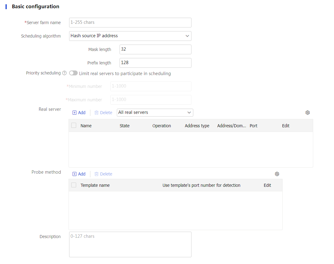
Table-3 Basic configuration items
Item
Description
Server farm name
Enter a name for the server farm, case insensitive.
Scheduling algorithm
Select a scheduling algorithm for the server farm.
Round robin —Assigns user requests to real servers based on the weights of real servers. A higher weight indicates more user requests will be assigned.Random —Randomly assigns user requests to real servers.Weighted least connection s —Always assigns user requests to the real server with the fewest number of weighted active connections (the number of active connections divided by weight). The weight used by this algorithm is configured on theCreate R eal Server page.Bandwidth —Distributes user requests to real servers according to the product ratio of the weights and remaining bandwidth of real servers. For example, if the remaining bandwidths for real serversrs1 andrs2 are 150 kbps and 250 kbps, respectively, and their weights are 5 and 6, the traffic distribution ratio is 150×5:250×6, which is 1:2.Maximum bandwidth —Distributes user requests always to an idle real server that has the largest remaining bandwidth. For example, if the remaining bandwidths of real serversrs1 andrs2 are 150 kbps and 250 kbps, respectively, the bandwidth difference is 100 kbps.When the request traffic is less than 100 kbps, all traffic is allocated to
rs2 .When the request traffic is more than 100 kbps, such as 130 kbps, 100 kbps is allocated to
rs2 , and the remaining 30 kbps is evenly distributed between both servers.
Dynamic feedback —Assigns new connections to real servers based on load weight values calculated by using the memory, CPU, and disk usage of the real servers. The less the load, the greater the weight value. A real server with a greater weight value is assigned more connections.L east time —Assigns new connections to real servers based on load weight values calculated by using the response time of the real servers. The shorter the response time, the greater the weight value. A real server with a greater weight value is assigned more connections.S ource IP address hash —Hashes the source IP address of user requests and distributes user requests to different real servers according to the hash values. This algorithm applies to a scenario where user requests with the same source IP address need to be distributed to the same real server.Source IP address CARP hash —Hashes the source IP address of user requests and distributes user requests to different real servers according to the CARP hash values. This algorithm applies to a scenario where user requests with the same source IP address need to be distributed to the same real server. When the number of available real servers changes, this algorithm makes all available real servers have the smallest load changes.S ource IP address and port number hash —Hashes the source IP address and port number of user requests and distributes user requests to different real servers according to the hash values. This algorithm applies to a scenario where user requests with the same source IP address and port number need to be distributed to the same real server.Source IP address and port number CARP hash —Hashes the source IP address and port number of user requests and distributes user requests to different real servers according to the CARP hash values. This algorithm applies to a scenario where user requests with the same source IP address and port number need to be distributed to the same real server. When the number of available real servers changes, this algorithm makes all available real servers have the smallest load changes.D estination IP address hash —Hashes the destination IP address of user requests and distributes user requests to different real servers according to the hash values. This algorithm applies to a scenario where a client needs to communicate with a real server repeatedly.Destination IP address CARP hash —Hashes the destination IP address of user requests and distributes user requests to different real servers according to the CARP hash values. This algorithm applies to a scenario where a client needs to communicate with a real server repeatedly. When the number of available real servers changes, this algorithm makes all available real servers have the smallest load changes.HTTP hash —Hashes the content of user requests and distributes user requests to different real servers according to the hash values. This scheduling algorithm takes effect only for an HTTP virtual server.HTTP CARP hash —Hashes the content of user requests and distributes user requests to different real servers according to the CARP hash values. When the number of available real servers changes, this algorithm makes all available real servers have the smallest load changes. This scheduling algorithm takes effect only for an HTTP virtual server.Weighted least connection s ( member ) —Always assigns user requests to the real server with the fewest number of weighted active connections (the number of active connections divided by weight). The weight used by this algorithm is configured on theReal Server page.L east time ( member ) —Always assigns user requests to real servers based on load weight values calculated by using the response time of the real servers. The shorter the response time, the greater the weight value. A real server with a greater weight value is assigned more connections.
By default, the round robin algorithm is used.
Offset
Specify the offset value based on the start of the HTTP content.
This parameter is supported only when the scheduling algorithm is HTTP hash or HTTP CARP hash.
Start string
Specify the regular expression that marks the start of the HTTP content, a string starting from the offset value. The string cannot contain question marks (?).
This parameter is supported only when the scheduling algorithm is HTTP hash or HTTP CARP hash.
Length/End string
Length specifies the length of the HTTP content.E nd string specifies the regular expression that marks the end of the HTTP content, a string starting from the start string value. The string cannot contain question marks (?).
This parameter is supported only when the scheduling algorithm is HTTP hash or HTTP CARP hash.
Priority scheduling
Specify the upper limit and lower limit of real servers in a server farm that can be scheduled. By default, all real servers with the highest priority in a server farm are scheduled.
If the number of real servers with the highest priority is greater than the configured maximum number, the maximum number
If the number of such real servers is less than the minimum number, real servers with lower priority are selected to meet the minimum number or until no real servers are available.
The real server priority can be configured on the
Real Servers page.Real server
You can add a real server to a server farm in one of the following ways:
Create a real server and add it to the server farm.
Click
Add , and selectCreate real server .Configure the parameters for the real server (see "Configure a real server").
Click
OK . The new real server appears in the real server list.
Select an existing real server.
Click
Add , and selectAdd existing real server .Select a real server from the list, and configure real server parameters (see "Configure a real server").
Click
OK . The real server appears in the real server list.
Probe method
Specify a probe template used by the server farm to detect the health and availability of its real servers. You can configure this parameter by using one of the following methods:
Configure the parameter globally for all members in the server farm on the
Server Farm s page, facilitating configuration and management.Configure the parameter for a specific real server farm member from the real server list on the
Server Farm s page or on theReal Servers page.
The parameter setting specific to a real server takes precedence over the global setting.
The probe result of a real server affects the use of the corresponding server farm member. The probe result of a server farm member does not affect the use of the corresponding real server.
You can select an existing probe template or create a probe template.
To create a probe template:
Click
Add .Template name: Enter a name for the probe template.
Use template's port number for detection: If you select this option, the destination port number specified in the template is used for detection. If you do not select this option, the real server's port number is used for detection.
Click
OK . The new probe template appears on theHealth Monitoring page.
Description
Enter a description for the server farm.
(Optional.) Configure advanced server farm settings.
Figure-10 Advanced server farm settings
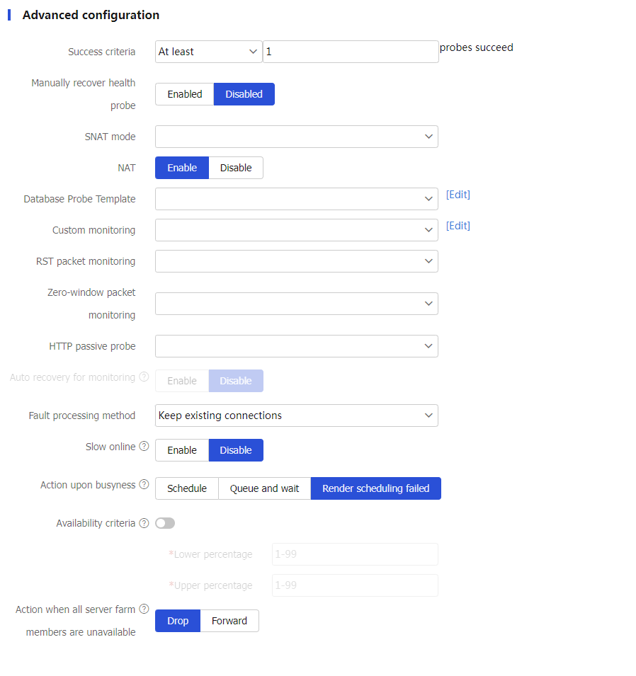
Table-4 Advanced configuration items
Item
Description
Success criteria
Specify the health monitoring success criteria for the real server.
All probes succeed: Health monitoring succeeds only when all the specified health monitoring methods succeed.
At least n probes succeed: Health monitoring succeeds when a minimum of the specified number of health monitoring methods succeed. When the specified number of health monitoring methods is greater than the number of health monitoring methods on the device, health monitoring succeeds if all health monitoring methods succeed.
Manually recover health probe
Enable or disable the health probe manual recovery feature.
With this feature disabled, the device automatically restores the state of a server farm member to available after health monitoring succeeds for the server farm member. With this feature enabled, after health monitoring succeeds for the server farm member, you must manually restore the state of the server farm member to available on the real server list of the
Edit Server Farm page.SNAT mode
Specify an SNAT mode for the server farm.
SNAT pool: Translates the source IP address into an IP address in the specified SNAT address pool.
Auto mapping: Translates the source IP address into the IP address of the interface connecting to the real servers.
TCP option: Translates the source IP address into the IP address carried in the TCP option field of packets.
If SNAT is not configured for a server farm, the server farm uses global SNAT policies for address translation.
SNAT pool name
Select an existing SNAT pool or create an SNAT pool for the server farm.
This parameter is supported only when the SNAT mode is SNAT pool.
NAT
Disable NAT for the server farm in indirect-mode NAT configuration, or enable NAT for the server farm in NAT-mode configuration.
RST packet monitoring
Select an existing RST probe template or create an RST probe template for the server farm.
Zero-window packet monitoring
Select an existing zero-window probe template or create a zero-window probe template for the server farm.
HTTP passive probe
Select an existing HTTP passive probe template or create an HTTP passive probe template for the server farm.
Custom monitoring
Select an existing custom probe template or create a custom probe template for the server farm.
This parameter does not take effect for server farm members configured with domain names.
Auto recovery
Enable or disable auto recovery. This function enables automatic recovery for real servers shut down by intelligent probe templates when the auto recovery timer expires.
If health monitoring is not configured, a real server is recovered to the unknown state.
If health monitoring is configured and succeeds, a real server is recovered to the available state. If health monitoring fails, a real server is recovered to the health-monitoring-failed state.
This function is available only when an HTTP passive, RST, or zero-window probe template is specified for a server farm.
Recovery time
Enter the auto recovery time. The value 0 means that real servers cannot automatically recover.
This parameter is available only when auto recovery is enabled.
Fault processing method
Specify the fault processing method for the real server.
Keep existing connections —Keeps the connection with the failed real server. Keeping or terminating the connection depends on the timeout mechanism of the protocol.Redirect connections —Redirects the connection to another available real server in the server farm.Terminate existing connections —Terminates the connection with the failed real server by sending RST packets (for TCP packets) or ICMP unreachable packets (for other types of packets).
Slow online
The real servers newly added to a server farm might not be able to immediately process large numbers of services assigned by the LB device. To resolve this issue, enable the slow online feature for the server farm. The feature uses the standby timer and ramp-up timer. When the real servers are brought online, the LB device does not assign any services to the real servers until the standby timer expires. When the standby timer expires, the ramp-up timer starts. During the ramp-up time, the LB device increases the service amount according to the processing capability of the real servers, until the ramp-up timer expires.
Standby time: The value range is 0 to 600 seconds.
Ramp-up time: The value range is 3 to 600 seconds.
Action upon busyness
Specify the action to take when the server farm is busy. A server farm is considered busy when all its real servers are busy. You can configure one of the following actions:
Schedule —Forcibly assigns connection requests to all real servers in the server farm.Queue and wait —Stops assigning connection requests to a server farm and assigns new connection requests to a wait queue.Queue length : New connection requests will be dropped when the queue length exceeds the configured length.Timeout time : Connection requests already in the queue will be aged out when the configured timeout time expires.
Render scheduling failed —Stops assigning client requests to a server farm. If the LB policy for the server farm contains the action of matching the next rule, the device compares client requests with the next rule. Otherwise, the device drops the client requests.
The device determines whether a real server is busy based on the following factors:
Maximum number of connections.
Maximum number of connections per second.
Maximum number of HTTP requests per second.
Maximum bandwidth, maximum inbound bandwidth, and maximum outbound bandwidth.
SNMP-DCA probe result.
Availability criteria
Set the criteria (lower percentage and upper percentage) to determine whether a server farm is available. This helps implement traffic switchover between the master and backup server farms.
Lower percentage —When the number of available real servers to the total number of real servers in the primary server farm is smaller than the lower percentage, traffic is switched to the backup server farm.Upper percentage —When the number of available real servers to the total number of real servers in the primary server farm is greater than the upper percentage, traffic is switched back to the master server farm.
Action when all server farm members are unavailable
Specify an action to take when all server farm members are unavailable:
Drop .Forward —Forwards requests to the most recently selected server farm member.
Click
OK . The new server farm appears on theServer Farm page.
Configure a real server
A real server is an entity on the LB device to process user services. A real server can belong to multiple server farms. A server farm can have multiple real servers.
To configure a real server:
Select
Polic ies >LB Policy >Server Load Balancing >Real Server s .Click
Create .Create a real server and configure basic real server settings.
Figure-11 Basic real server settings
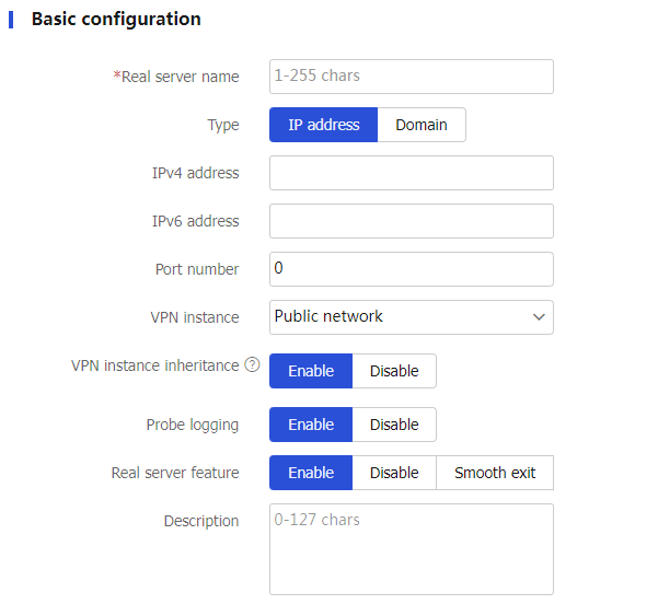
Table-5 Basic configuration items
Item
Description
Real server name
Enter a name for the real server, case insensitive.
Type
Select the real server type:
IP address .Domain .
IPv4 address
Specify an IPv4 address for the real server.
The IPv4 address cannot be a loopback address, multicast address, broadcast address, or an address in the format of 0.X.X.X.
IPv6 address
Specify an IPv6 address for the real server.
The IPv6 address cannot be a loopback address, multicast address, link-local address, or all-zero address.
Domain
Specify a domain name for the real server.
After you specify a domain name for the real server, the device immediately sends a domain name query request to the DNS server, and creates a real server named
auto_ X.X.X.X based on the query results. If the specified domain name is resolved into multiple IP addresses, the device automatically creates multiple real servers.To specify a domain name for the real server, you must specify a DNS server on the
DNS page for domain name resolution.Do not specify the same domain name for different real servers.
Port number
Specify the port number for the real server. If the port number is 0, packets use their respective port numbers.
VPN instance
Specify a VPN instance for the real server.
VPN instance inheritance
Enable or disable VPN instance inheritance.
When VPN instance inheritance is enabled, a real server without a VPN instance specified inherits the VPN instance of its virtual server.
Probe logging
Enable or disable logging for health monitoring.
This feature logs heath status changes of the real server.
Real server feature
Enable or disable the real server feature. Options include:
Enable .Disable —Immediately tear down the existing connections for the real server.Smooth exit —Process traffic only for the existing connections and existing sticky entries, and maintain health monitoring for the real server.Slow offline —Stop establishing new connections and wait for the existing connections to expire.
Description
Enter a description for the real server.
(Optional.) Configure advanced real server settings.
Figure-12 Advanced real server settings
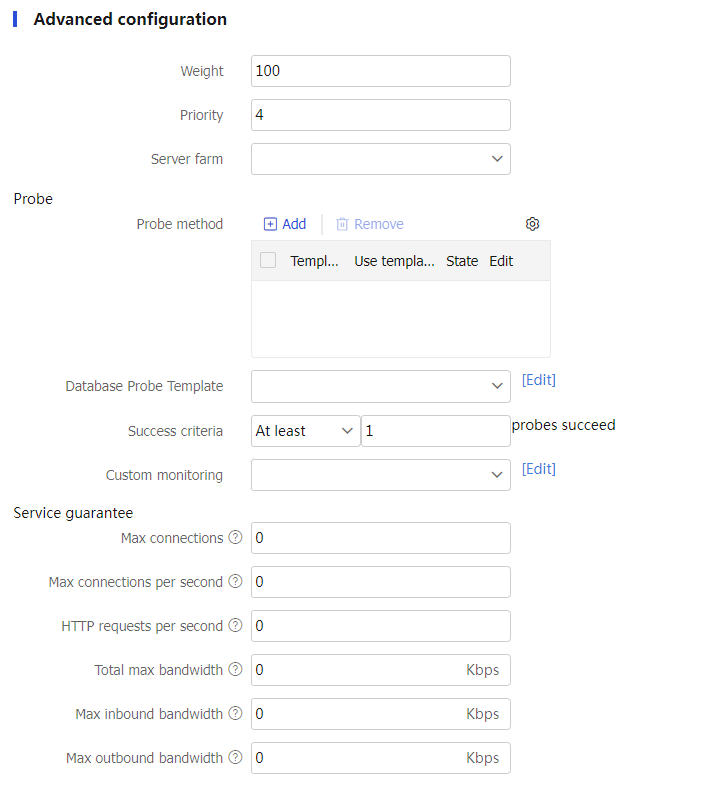
Table-6 Advanced configuration items
Item
Description
Weight
Enter the weight for the real server. A greater value means a higher priority to be selected.
Priority
Enter a priority for the real server in the server farm. A greater value means a higher priority to be selected.
If the number of real servers with the highest priority is smaller than the configured minimum number, real servers with lower priority are selected to meet the minimum number.
You can configure the maximum number and minimum number on the
Server Farm s page.Server farm
Select an existing server farm or create a server farm for the real server.
Probe-Probe method
Specify a probe template used by the real server to detect the health and availability. You can configure this parameter by using one of the following methods:
Configure the parameter globally for all members in the server farm on the
Server Farm s page, facilitating configuration and management.Configure the parameter for a specific real server farm member from the real server list on the
Server Farm s page or on theReal Servers page.
The parameter setting specific to a real server takes precedence over the global setting.
The probe result of a real server affects the use of the corresponding server farm member. The probe result of a server farm member does not affect the use of the corresponding real server.
You can select an existing probe template or create a probe template
To create a probe template:
Click
Add .Template name: Enter a name for the probe template.
Use template's port number for detection: If you select this option, the destination port number specified in the template is used for detection. If you do not select this option, the real server's port number is used for detection.
Click
OK . The new probe template appears on theHealth Monitoring page.
Probe-Success criteria
Specify the health monitoring success criteria for the real server.
All probes succeed: Health monitoring succeeds only when all the specified health monitoring methods succeed.
At least n probes succeed: Health monitoring succeeds when a minimum of the specified number of health monitoring methods succeed. When the specified number of health monitoring methods is greater than the number of health monitoring methods on the device, health monitoring succeeds if all health monitoring methods succeed.
Custom monitoring
Select an existing custom probe template or create a custom probe template for the real server.
This parameter is not available for real servers configured with domain names.
Manually recover health probe
Enable or disable the health probe manual recovery feature.
With this feature disabled, the device restores the state of a server farm member to available after health monitoring succeeds for the server farm member. With this feature enabled, after health monitoring succeeds for the server farm member, you must manually restore the state of the server farm member to available on the real server list of the
Edit Server Farm page.This parameter is available only for server farm members.
Variables
Configure a variable for a server farm member.
To configure a variable:
Click
Add .Name: Enter a variable name, case-sensitive.
Value: Enter a variable value, case-sensitive.
Click
OK . The new variable appears in theV ariable s list.
This variable is used to rewrite the TCP payload in a general LB action. The specific content in the TCP payload will be replaced with the variable value associated with a server farm member. For example, if you configure a variable with name
var1 and value_1 and configure an action of rewritingQMGR.S01 asQMGR.S01 % [var1] , theQMGR.S01 string in the TCP payload is rewritten asQMGR.S01_1 .QoS-Max connections
Specify the maximum number of connections for the real server. 0 means not limited.
QoS-Max connections per second
Specify the maximum number of connections per second for the real server. 0 means not limited.
QoS-HTTP requests per second
Specify the maximum number of HTTP requests per second for the real server. 0 means not limited.
QoS-Total max bandwidth
Specify the maximum bandwidth for the real server. 0 means not limited.
QoS-Max inbound bandwidth
Specify the maximum inbound bandwidth for the real server. 0 means not limited.
QoS-Max outbound bandwidth
Specify the maximum outbound bandwidth for the real server. 0 means not limited.
Click
OK . The new real server appears on theReal Server page.
Configure an LB policy (optional)
An LB policy associates a class with an action to guide packet forwarding. In an LB policy, you can configure an action for packets matching the specified class, and configure the default action for packets matching no class.
You can specify multiple classes for an LB policy. Packets match the classes in the order the classes are configured. If a class is matched, the specified action is taken and packets stop matching the subsequent classes. As a best practice for finer matching when a class rule is included in the rule of another class, configure the class with more detailed rule first. If no class is matched, the default action is taken.
An LB policy can be used by a virtual server.
A Diameter LB policy takes effect only for Diameter requests.
Configure a class
Select
Polic ies >LB Policy >Server Load Balancing >Advanced Policies >Class .Click
Create .Create a class.
Figure-13 Class settings
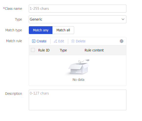
Table-7 Class configuration items
Item
Description
Class name
Enter a name for the class, case insensitive.
Type
Specify the type for the class.
Generic: Applies to Layer 4 server load balancing.
HTTP: Applies to Layer 7 server load balancing.
RADIUS: Applies to Layer 7 server load balancing.
MySQL: Applies to Layer 7 server load balancing.
Diameter: Applies to Layer 7 server load balancing. Diameter is a protocol that provides authentication, authorization, and accounting services for computer networks. It evolved from the RADIUS protocol.
Match type
Specify the match type for the class.
Match any: Requires matching any rule of the LB class.
Match all: Requires matching all rules of the LB class.
Match rule
A class classifies packets by comparing packets with specific rules. Matching packets are further processed by actions. You can create a maximum of 65535 rules for a class.
Click
Create to create a match rule.Rule ID: Specify the rule ID. Rules are matched in ascending order of rule IDs.
Type: Specify the rule type. The rule types include source IPv4 address, source IPv6 address, class, IPv4 ACL, IPv6 ACL, cookie, HTTP header, method, URL, content, user, RADIUS attribute, input interface, HTTP version, ISP, TCP payload, MySQL, application ID, and destination realm.
IPv4 address: Specify an IPv4 address. This parameter is available only when the rule type is source IPv4 address.
Mask length: Specify a mask length. This parameter is available only when the rule type is source IPv4 address.
IPv6 address: Specify an IPv6 address. This parameter is available only when the rule type is source IPv6 address.
Prefix length: Specify a prefix length. This parameter is available only when the rule type is source IPv6 address.
Class: Specify a class. This parameter is available only when the rule type is class.
ACL: Specify an ACL. You can select an existing ACL or create an ACL. This parameter is available only when the rule type is IPv4 ACL or IPv6 ACL.
Cookie name: Specify the cookie name for HTTP packets. The cookie name is a case-sensitive string excluding spaces, horizontal tabs, ASCII characters smaller than or equal to 31, ASCII characters greater than or equal to 127, or the following characters: ( ) < > @ , ; : \ " / [ ] ? = { }. This parameter is available only when the rule type is cookie.
Cookie value: Specify the cookie value regular expression. The string cannot contain question marks (?). This parameter is available only when the rule type is cookie.
Header name: Specify the header name for HTTP packets. The header name is a case-insensitive string excluding spaces, horizontal tabs, ASCII characters smaller than or equal to 31, ASCII characters greater than or equal to 127, or the following characters: ( ) < > @ , ; : \ " / [ ] ? = { }. This parameter is available only when the rule type is HTTP header.
Header value: Specify the header value regular expression. The string cannot contain question marks (?). This parameter is available only when the rule type is HTTP header.
Extension type: The extension type can be
Predefined orCustom . This parameter is available only when the rule type is method.Method: The predefined methods include GET, CONNECT, DELETE, HEAD, OPTIONS, POST, PUT, and TRACE. The custom method is a case-sensitive string excluding spaces, horizontal tabs, ASCII characters smaller than or equal to 31, ASCII characters greater than or equal to 127, or the following characters: ( ) < > @ , ; : \ " / [ ] ? = { }. This parameter is available only when the rule type is method.
URL: Specify the URL regular expression. The string cannot contain question marks (?). This parameter is available only when the rule type is URL.
Content offset: Specify the offset value of the HTTP entity based on the start of the HTTP packet. This parameter is available only when the rule type is content.
Content value: Specify the HTTP entity regular expression. The string cannot contain question marks (?). This parameter is available only when the rule type is content.
User: Select an existing user or user group in an identity domain, or create a user or user group. This parameter is available only when the rule type is user.
Attribute type: Enter an attribute type value. This parameter is available only when the rule type is RADIUS attribute.
Attribute value: Specify the RADIUS attribute regular expression. This parameter is available only when the rule type is RADIUS attribute.
Input interface: Specify an input interface. This parameter is available only when the rule type is input interface.
HTTP version: Specify an HTTP version. This parameter is available only when the rule type is HTTP version.
ISP: Select an existing ISP, or create an ISP. This parameter is available only when the rule type is ISP.
TCP payload: Enter a regular expression used to match TCP payloads. This parameter is available only when the rule type is TCP payload.
Case insensitivity: Enable case insensitivity for matching. This parameter is available only when the rule type is TCP payload or MySQL.
Negate the match rule: If this option is not selected, an LB action is taken when TCP packets match the regular expression. If this option is selected, an LB action is taken when TCP packets do not match the regular expression. This parameter is available only when the rule type is TCP payload or MySQL.
Regular expression: Enter a regular expression used to match MySQL statements. This parameter is available only when the rule type is MySQL.
Application ID: Specify an application ID. An LB action is taken when the application ID in a Diameter request matches the specified application ID. The application ID must be an application ID value defined in the Diameter Base Protocol and its extensions. This parameter is available only when the rule type is Diameter.
Destination Realm: Specify a destination realm. An LB action is taken when the destination realm in a Diameter request matches the specified destination realm. This parameter is available only when the rule type is Diameter.
Click
OK .
Description
Enter a description for the class.
Click
OK . The new class appears on theClass page.
Configure an action
Select
Polic ies >LB Policy >Server Load Balancing >Advanced Policies >Action .Click
Create .Create an action and configure basic action settings.
Figure-14 Basic action settings
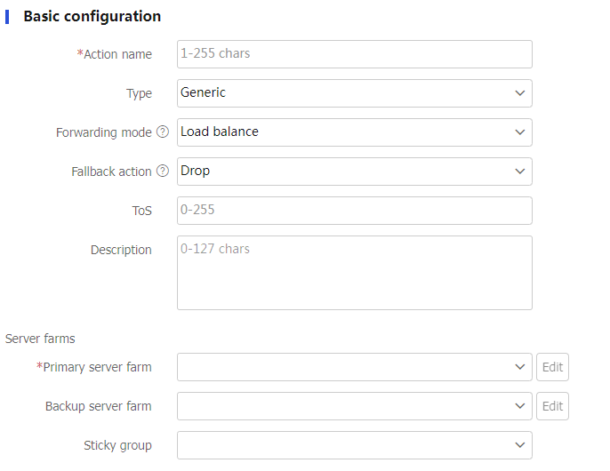
Table-8 Basic configuration items
Item
Description
Action name
Enter a name for the action, case insensitive.
Type
Specify an action type.
Generic
HTTP
HTTP redirection
RADIUS
Diameter
Forwarding mode
Specify a forwarding mode:
Load balance
Drop
Forward (supported by generic type and RADIUS type only)
Respond by using a file (supported by HTTP type only)
If the LB policy is used by a SIP, HTTP, HTTP redirection, HTTPS, MySQL, or Layer 7 TCP virtual server, the
Forward option does not take effect.Uncompressed file
If the URL path in a client request matches the specified URL path, the device responds to the request by using an uncompressed file.
Click
Create to create an uncompressed response file.URL path: Specifies the URL path used to match HTTP requests, a case-sensitive string. The specified URL path must start with a forward slash (/).
Uncompressed file: Specifies an uncompressed file by its absolute path plus a file name, which is case insensitive, for example, flash:/file.html. Only one uncompressed file can be used for a URL, and one uncompressed file can be used for multiple URLs.
Click
OK .
This parameter is available only when the forwarding mode is
R espond by using a file .Compressed file
If the URL path in a client request matches the specified working path plus a relative path
/index and compressed file asflash:/za/zb/test.zip , and a relative path/css/col.css exists intest.zip , the matching URL is/index/css/col.css and the response file iscol.css .Working path: Specify a working path plus a relative path in the zip file to match the URL in HTTP requests, a case-sensitive string. The working path must start with a forward slash.
Compressed file: Specify a compressed file by its absolute path plus a file name, which is case insensitive. The file must be a zip file, for example, flash:/file.zip.
This parameter is available only when the forwarding mode is
R espond by using a file .Fallback action
Specify a fallback action.
Drop: Drops packets upon failure to find an available real server.
Match next rule: Matches the next rule upon failure to find an available real server.
Respond by using another file: Responds to client requests with the specified default response file upon failure to find an available real server. Make sure the response file is a complete HTTP packet, rather than only the content of HTTP packet body.
Default response file: Specifies an uncompressed file by its absolute path plus a file name, which is case insensitive, for example, flash:/file.html.
Fin close: Sends FIN packets to close the TCP connection.
Rst close: Sends RST packets to close the TCP connection.
This parameter is available only when the forwarding mode is
Load balance .If the LB policy is used by a SIP virtual server, the
Match next rule option does not take effect.Action taken upon failure to find the response file
Specify an action taken upon failure to find the response file.
Drop: Drops packets upon failure to find an available real server.
Match next rule: Matches the next rule upon failure to find a response file.
Respond by using a file: Responds to client requests with the specified default response file upon failure to find a response file. Make sure the response file is a complete HTTP packet, rather than only the content of HTTP packet body.
Default response file: Specifies an uncompressed file by its absolute path plus a file name, which is case insensitive, for example, flash:/file.html.
Fin close: Sends FIN packets to close the TCP connection.
Rst close: Sends RST packets to close the TCP connection.
This parameter is available only when the forwarding mode is
R espond by using a file .TCP connection close mode
Specify a TCP connection close mode.
By sending FIN: Sends FIN packets to close the TCP connection.
By sending RST: Sends RST packets to close the TCP connection.
This parameter is available only when the forwarding mode is
Drop .ToS
Set the ToS field value of IP packets sent to the server.
Description
Enter a description for the action.
Server farms-Primary server farm
Select an existing server farm or create a server farm as the primary server farm.
When the primary server farm is available (contains real servers), packets are forwarded through the primary server farm. When the primary server farm is not available, packets are forwarded through the backup server farm.
This parameter is available only when the forwarding mode is
Load balance .Server farms-Backup server farm
Select an existing server farm or create a server farm as the backup server farm.
This parameter is available only when the forwarding mode is
Load balance .Server farms-Sticky group
Select an existing sticky group or create a sticky group.
This parameter is available only when the forwarding mode is
Load balance .HTTP redirection configuration-Redirection URL
This setting redirects all HTTP request packets matching an action to the specified URL.
Specify a redirection URL, a case-sensitive string. You can also specify the question mark (?) or the following character strings as the redirection URL:
%h: Specifies the host name in the client request packet.
%p: Specifies the URL in the client request packet.
%%: Specifies the percentage sign (%).
This parameter is available only when the action type is HTTP redirection.
HTTP redirection configuration -Redirection mode
Specify a redirection mode.
Temporary-302
Temporary-307
Permanent-301
This parameter is available only when the action type is HTTP redirection.
(Optional.) Configure advanced action settings.
Figure-15 Advanced action settings
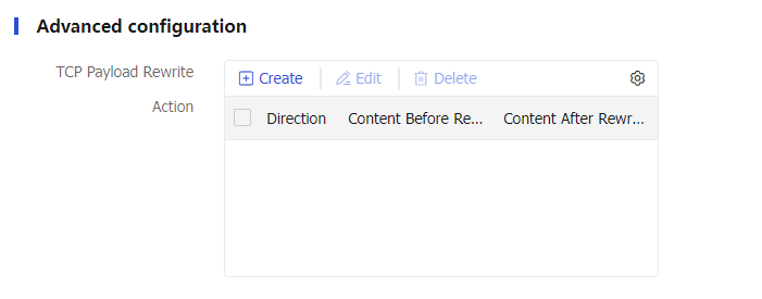
Table-9 Advanced configuration items
Item
Description
TCP payload rewrite
Click
Create .Direction: Specify the direction, which can be
Both ,Request , orResponse .Content before rewrite: TCP message body to rewrite, a case-sensitive regular expression string.
Content after rewrite: TCP message body after rewrite. You can also specify the following replacement strings:
%[ variable ] —Replaces the specified value with the variable associated with the server farm member. Thevariable is the variable name.%[1-9] —Replaces the specified value with the content in the corresponding parentheses. For example, if you configure the content before rewrite as(Wel)(co)(me) and the content after rewrite as%2 , the stringWelcome will be replaced withco in the second pair of parentheses.
Click
OK .
This parameter is supported only in a generic LB action.
Only TCP virtual servers operating at Layer 7 support an LB policy containing the TCP payload rewrite configuration.
Insert X-Forwarded-For
Insert the X-Forwarded-For header.
If you enable this feature, you do not need to enable the Insert X-Forwarded-For feature for the virtual server. If you enable both features, the Insert X-Forwarded-For feature for the virtual server takes effect.
This parameter is supported only in an HTTP LB action.
Response content rewrite-Content before rewrite
Specify the HTTP packet content to be rewritten.
This parameter is supported only in an HTTP LB action.
Response content rewrite-Content after rewrite
Specify the HTTP packet content after rewrite.
%is: Source IPv4 or IPv6 address.
%ps: Source port number.
%id: Destination IPv4 or IPv6 address.
%pd: Destination port number.
%%: Percentage sign (%).
%[1-9] : Header value enclosed in parenthesis.
This parameter is supported only in an HTTP LB action.
Header deletion
Click
Create .Direction: Specify the direction, which can be
Both ,Request , orResponse .Header name: Specify the header name, which is case insensitive and can be predefined or customized. It cannot contain spaces, horizontal tabs, ASCII characters less than or equal to 31, ASCII characters greater than or equal to 127, or the following characters: ( ) < > @ , ; : \ " / [ ] ? = { }.
Click
OK .
This parameter is supported only in an HTTP LB action.
Header insertion
Click
Create .Direction: Specify the direction of HTTP packets, which can be
Both ,Request , orResponse .Header name: Specify the header name, which is case insensitive and can be predefined or customized. It cannot contain spaces, horizontal tabs, ASCII characters less than or equal to 31, ASCII characters greater than or equal to 127, or the following characters: ( ) < > @ , ; : \ " / [ ] ? = { }.
Header value: Specify the header content to be inserted to the HTTP packet. The string cannot contain question marks (?). You can also specify the following replacement strings:
%is: Source IP address in HTTP requests.
%ps: Source port number in HTTP requests.
%id: Destination IP address in HTTP requests.
%pd: Destination port number in HTTP requests.
%sps: Source port number in HTTP responses.
%spd: Destination port number in HTTP responses.
%sis: Source IP address in HTTP responses.
%sid: Destination IP address in HTTP responses.
%{x509v}: Certificate version.
%{x509snum}: Certificate serial number.
%{x509sigalgo}: Certificate signature algorithm.
%{x509issuer}: Certificate issuer.
%{x509before}: Certificate effective time.
%{x509after}: Certificate expiration time.
%{x509sub}: Certificate subject.
%{x509spktype}: Public key type for the certificate subject.
%{x509spk}: Public key for the certificate subject.
%{x509spkRSA}: Length of the RSA public key for the certificate subject (available only for an RSA public key).
%{x509hash}: MD5 hash value of the client certificate.
%{x509whole}: All content of the certificate. To configure this variable, you must specify the encoding method as
Base64 .%{x509cipher}: Cipher suites of the certificate.
%{dncn}: Issuee.
%{dne}: Email.
%{dno}: Company/Organization.
%{dnou}: Department.
%{dnc}: Country.
%{dns}: State/Province.
%{dnl}: City.
Encoding method: Specify an encoding method for replacement strings, which can be
Not encoded ,URL , orBase64 . URL encoding encodes only spaces and the following special characters in replacement strings ; / ? : @ & = + $ | { } , \ ^ [ ] ` < > # %. Base64 encoding encodes entire replacement strings.
Click
OK .
This parameter is supported only in an HTTP LB action. To insert certificate information, you must enable client verification for the SSL server policy.
Header rewrite
Click
Create .Direction: Specify the direction of HTTP packets, which can be
Both ,Request , orResponse .Header name: Specify the header name, which is case insensitive and can be predefined or customized. It cannot contain spaces, horizontal tabs, ASCII characters less than or equal to 31, ASCII characters greater than or equal to 127, or the following characters: ( ) < > @ , ; : \ " / [ ] ? = { }.
Header value: Specify the header content after rewrite. The string cannot contain question marks (?). You can also specify the following replacement strings:
%is: Source IP address in HTTP requests.
%ps: Source port number in HTTP requests.
%id: Destination IP address in HTTP requests.
%pd: Destination port number in HTTP requests.
%sps: Source port number in HTTP responses.
%spd: Destination port number in HTTP responses.
%sis: Source IP address in HTTP responses.
%sid: Destination IP address in HTTP responses.
%1-9: Specified string used for replacement. A maximum of nine items are supported.
%{x509v}: Certificate version.
%{x509snum}: Certificate serial number.
%{x509sigalgo}: Certificate signature algorithm.
%{x509issuer}: Certificate issuer.
%{x509before}: Certificate effective time.
%{x509after}: Certificate expiration time.
%{x509sub}: Certificate subject.
%{x509spktype}: Public key type for the certificate subject.
%{x509spk}: Public key for the certificate subject.
%{x509spkRSA}: Length of the RSA public key for the certificate subject (available only for an RSA public key).
%{x509hash}: MD5 hash value of the client certificate.
%{dncn}: Issuee.
%{dne}: Email.
%{dno}: Company/Organization.
%{dnou}: Department.
%{dnc}: Country.
%{dns}: State/Province.
%{dnl}: City.
Encoding method: Specify an encoding method for replacement strings, which can be
Not encoded ,URL , orBase64 . URL encoding encodes only spaces and the following special characters in replacement strings ; / ? : @ & = + $ | { } , \ ^ [ ] ` < > # %. Base64 encoding encodes entire replacement strings.
Click
OK .
This parameter is supported only in an HTTP LB action.
URL rewrite
Click
Create .URL to be rewritten: The URL content cannot contain question marks (?).
URL after rewrite: Specify the URL content after rewrite. You can also specify the following replacement strings:
%is: Source IP address in HTTP requests.
%ps: Source port number in HTTP requests.
%id: Destination IP address in HTTP requests.
%pd: Destination port number in HTTP requests.
%sps: Source port number in HTTP responses.
%spd: Destination port number in HTTP responses.
%sis: Source IP address in HTTP responses.
%sid: Destination IP address in HTTP responses.
%1-9: Specified string used for replacement. A maximum of nine items are supported.
%{x509v}: Certificate version.
%{x509snum}: Certificate serial number.
%{x509sigalgo}: Certificate signature algorithm.
%{x509issuer}: Certificate issuer.
%{x509before}: Certificate effective time.
%{x509after}: Certificate expiration time.
%{x509sub}: Certificate subject.
%{x509spktype}: Public key type for the certificate subject.
%{x509spk}: Public key for the certificate subject.
%{x509spkRSA}: Length of the RSA public key for the certificate subject (available only for an RSA public key).
%{x509hash}: MD5 hash value of the client certificate.
%{dncn}: Issuee.
%{dne}: Email.
%{dno}: Company/Organization.
%{dnou}: Department.
%{dnc}: Country.
%{dns}: State/Province.
%{dnl}: City.
Encoding method: Specify an encoding method for replacement strings, which can be
Not encoded ,URL , orBase64 . URL encoding encodes only spaces and the following special characters in replacement strings ; / ? : @ & = + $ | { } , \ ^ [ ] ` < > # %. Base64 encoding encodes entire replacement strings.
Click
OK .
This parameter is supported only in an HTTP LB action.
SSL security-SSL client policy
Select an existing SSL client policy or create an SSL client policy.
This parameter is supported only in an HTTP LB action.
SSL security-SSL redirection URL list
Click
Create .URL: Specify the Location header URL regular expression.
HTTP port: Specify the HTTP port number to be rewritten.
SSL port: Specify the SSL port number after rewrite.
Click
OK .
This parameter is supported only in an HTTP LB action.
Location header rewriting list for HTTP responses
Click
Create .Regular expression before rewriting: Specify a case-sensitive regular expression to match the content to be rewritten in the Location header of HTTP responses.
Location value after rewriting: Specify the Location header content after rewriting, which is case-sensitive.
Click
OK .
Location header rewriting for HTTP responses will be performed after SSL redirection URL rewriting.
This parameter is supported only in an HTTP LB action.
SSL client policy
Specify an SSL client policy to encrypt the matching traffic from the device (SSL client) to the SSL server.
You can select an existing SSL client policy or create an SSL client policy.
This parameter is supported only in a Diameter LB action.
TCP parameter profile (server side)
Specify a TCP parameter profile to process the traffic with the action of forwarding to a server farm. The TCP parameter profile processes and optimizes TCP connections between the device and the servers.
You can select an existing TCP parameter profile or create a TCP parameter profile.
This parameter is supported only in a Diameter LB action.
Diameter-Session parameter profile
Specify a Diameter-Session parameter profile to process traffic with the action of forwarding to a server farm.
You can select an existing Diameter-Session parameter profile or create a Diameter-Session parameter profile.
This parameter is supported only in a Diameter LB action.
Click
OK . The new action appears on theAction page.
Configure an LB policy
Select
Polic ies >LB Policy >Server Load Balancing >Advanced Policies >Load Balancing Policy .Click
Create .Create an LB policy.
Figure-16 LB policy settings
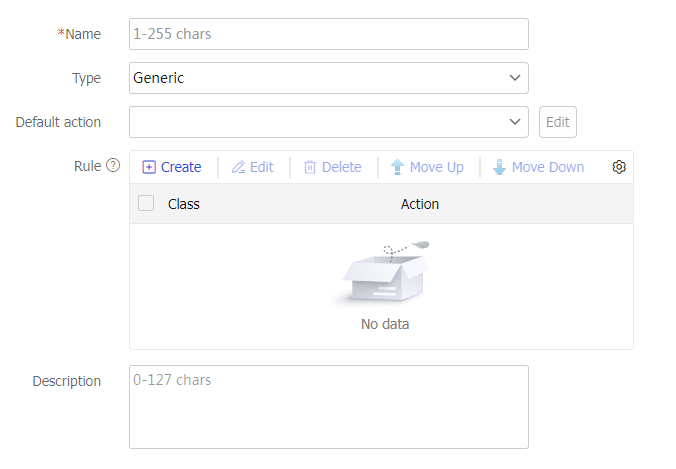
Table-10 LB policy configuration items
Item
Description
Name
Enter a name for the LB policy, case insensitive.
Type
Specify the type for the LB policy.
Generic: Applies to Layer 4 server load balancing.
HTTP: Applies to Layer 7 server load balancing.
RADIUS: Applies to Layer 7 server load balancing.
MySQL: Applies to Layer 7 server load balancing.
Diameter: Applies to Layer 7 server load balancing.
Default action
Specify a generic action for a generic LB policy, or specify any type of action for an HTTP LB policy.
You can select an existing action or create an action.
Rule
Specify an action for packets matching the specified class.
Click
Create .Class: Select an existing class or create a class.
Action: Select an existing action or create an action.
Insert before: Inserts the target class before a class.
Click
OK .
Description
Enter a description for the LB policy.
Click
OK . The new LB policy appears on theL oad B alancing Policy page.
Configure a connection limit policy (optional)
Using a connection limit policy can limit the number of connections on the device. It helps prevent a large number of connections from consuming too many device system resources and server resources. In this way, internal network resources (hosts or servers) are protected, and device system resources can be used more appropriately.
A connection limit policy can have multiple rules. Each rule specifies a range of users and the limit to the user connections. A connection limit policy applies only to the user connections matching a rule. When the number of connections for a certain type reaches the upper limit, the device does not accept new connection requests of that type. It accepts new connection requests only when the number of connections drops below the lower limit.
The user ranges in the rules are set by using ACLs.
To configure a connection limit policy:
Select
Polic ies >LB Policy >Server Load Balancing >Advanced Policies >Connection Limit Policy .Click
Create .Create a connection limit policy.
Figure-17 Connection limit policy settings
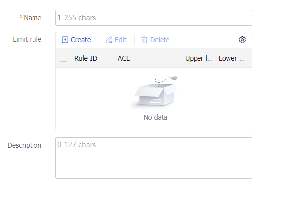
Table-11 Connection limit policy configuration items
Item
Description
Name
Enter a name for the connection limit policy, case insensitive.
Limit rule
Create a rule.
Click
Create .Rule ID: Specify an ID for the connection limit rule.
Type: Specify a connection limit rule type, which can be IPv4 ACL or IPv6 ACL.
ACL: Specify an ACL. You can select an existing ACL or create an ACL.
Limit by: Select source IP address, destination IP address, or service. Source IP address limits user connections by source IP address. Destination IP address limits user connections by destination IP address. Service limits user connections by service. Services are classified by transport layer protocol and service port number.
Connection limits-Upper limit: Specify the upper limit of connections. When the number of connections in a specified range or for a certain type reaches the upper limit, the device does not accept new connection requests.
Connection limits–Lower limit: Specify the lower limit of connections. The lower limit must be equal to or smaller than the upper limit. The device accepts new connection requests only when the number of connections drops below the lower limit.
Click
OK .
Description
Enter a description for the connection limit policy.
Click
OK . The new connection limit policy appears on theConnection Limit Policy page.
Configure a protection policy (optional)
You can specify a protection policy to protect the URLs specified in the protection policy. A protection action is taken if the number of times a user accesses a protected URL exceeds the configured protection threshold during the protection period.
To configure a protection policy:
Select
Polic ies >LB Policy >Server Load Balancing >Advanced Policies >Protection Policy .Click
Create .Create a protection policy.
Figure-18 Protection policy settings
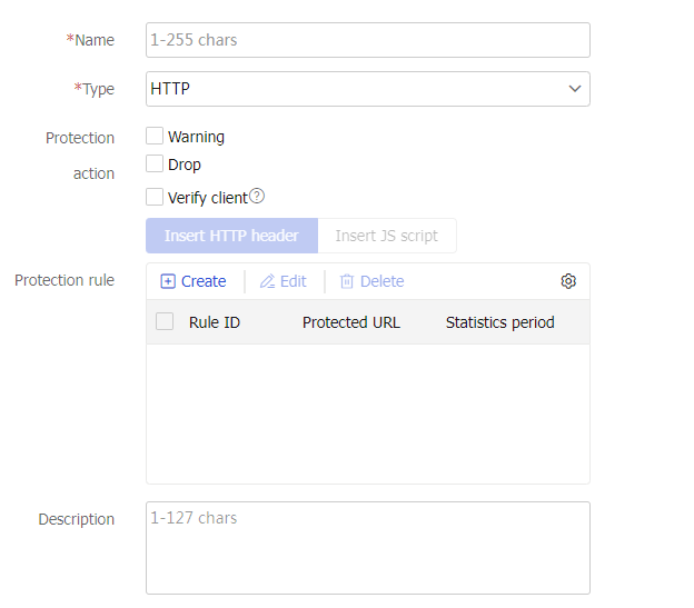
Table-12 Protection policy configuration items
Item
Description
Name
Enter a name for the protection policy, case insensitive.
Type
Specify the type for the protection policy.
The device supports only the HTTP type.
Protection action
Select protection actions. A protection action is taken if the number of times a user accesses a protected URL exceeds the configured protection threshold. You can specify the following protection actions:
Warning —Generates a log message and sends it to the information center.Drop —Drops requests.Verify client —Returns a response carrying a cookie value to the client. If a subsequent request carries the returned cookie value, it passes the verification. If a subsequent request does not carry a cookie value or carries a different cookie value, it fails to pass the verification and is dropped. The device supports returning a cookie value by inserting an HTTP header or a JS script.
Protection rule
A protection policy can contain multiple protection rules. Each protection rule defines the URLs to be protected and the protection period. A protection action is taken if the number of times a user accesses a protected URL exceeds the configured protection threshold during the protection period. The device supports using source-IP-based and cookie-based criteria to determine whether requests belong to the same user. If you configure both a cookie-based request threshold and a source-IP-based request threshold, the protection action is taken when either threshold is exceeded.
Click
Create to create a protection rule.Rule ID: Specify the rule ID.
Protected URL: Specify a regular expression to match URLs, a case-sensitive string. The regular expression cannot contain question marks (?).
Statistics period: Set the protection period. If the number of times that a user accesses a protected URL exceeds the request threshold during the protection period, the protection action is taken.
Source-IP-based threshold: Configure a source-IP-based request threshold.
Cookie name: Specify an HTTP cookie by its name, a case-sensitive string. The cookie name cannot contain brackets ({ }, ( ),[ ], < >), at sign (@), comma (,), semicolon (;), colon (:), backslash (\), quotation mark ("), slash (/), question mark (?), equal sign (=), space character (SP), and horizontal tab (HT). Additionally, the cookie name cannot contain ASCII codes that are less than or equal to 31 and greater than or equal to 127.
Cookie-based threshold: Configure a cookie-based protection threshold.
Click
OK .
Description
Enter a description for the protection policy.
Click
OK . The new protection policy appears on theProtection Policy page.
Configure a cache policy (optional)
A cache policy allows the device to cache the response packets from the server. When the device receives an HTTP request for a cached response, it replies with the cached response instead of sending the request to the server, thereby alleviating the pressure on the server.
| Support for this function depends on the device model. |

To configure a cache policy:
Select
Polic ies >LB Policy >Server Load Balancing >Advanced Policies >C ache Policy .Click
Create .Create a cache policy.
Figure-19 Cache policy settings
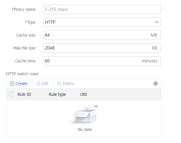
Table-13 Cache policy configuration items
Item
Description
Policy name
Enter a name for the cache policy, case insensitive.
Type
Enter the cache policy type.
Only the HTTP type is supported in the current software version.
Cache size
Specify the cache size allowed for the policy.
Max file size
Specify the maximum size of a single cached file. A file exceeding the maximum size is not cached.
Cache time
Specify the default cache time. If a response packet does not include the cache time, the default cache time applies. If a response packet includes the cache time, the included cache time or the default cache time applies, whichever is shorter.
HTTP match rule
Multiple HTTP match rules can be configured for a cache policy. Response packets that match the URI expression in an HTTP match rule are cached.
To create an HTTP match rule:
Click
Create .Rule ID: Enter a rule ID.
Rule type: Select a rule type. Only the URI type is supported in the current software version.
URI: Enter a regular expression string to match URIs. The string is case-insensitive and cannot contain question marks (?).
Click
OK . The new match rule appears in the match rule list.
Click
OK . The new cache policy appears on theC ache Policy page.
Configure a parameter profile (optional)
You can configure advanced parameters through a parameter profile. The virtual server references the parameter profile to analyze, process, and optimize service traffic.
To configure a parameter profile:
Select
Polic ies >LB Policy >Server Load Balancing >Parameter Profile s .Click
Create .Create a parameter profile.
Figure-20 Parameter profile settings
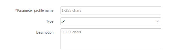
Table-14 Parameter profile configuration items
Item
Description
Parameter profile name
Enter a name for the parameter profile, case insensitive.
Type
Specify the type for the parameter profile.
IP: Applies to Layer 4 and Layer 7 server load balancing. For more information about IP parameter configuration.
TCP: Applies to Layer 4 and Layer 7 server load balancing. For more information about TCP parameter configuration.
HTTP: Applies to Layer 7 server load balancing. For more information about HTTP parameter configuration.
HTTP-Compression: Applies to Layer 7 server load balancing. For more information about HTTP compression parameter configuration.
HTTP-Statistics: Applies to Layer 7 server load balancing. For more information about HTTP statistics parameter configuration.
OneConnect: Applies to Layer 7 server load balancing. For more information about OneConnect parameter configuration.
TCP-Application: Applies to Layer 7 server load balancing. For more information about TCP application parameter configuration.
MySQL: Applies to Layer 7 server load balancing. For more information about MySQL application parameter configuration.
Diameter-Session: Applies to Layer 7 server load balancing. For more information about Diameter-Session parameter configuration.
HTTP2.0: Applies to Layer 7 server load balancing. For more information about HTTP/2 parameter configuration.
Description
Enter a description for the parameter profile.
Figure-21 IP parameter profile settings
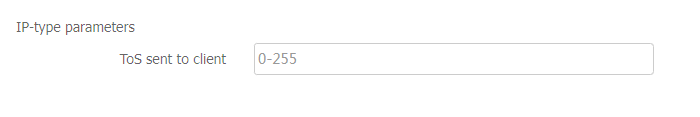
Table-15 IP parameter configuration items
Item
Description
ToS sent to client
Set the ToS field value of IP packets sent to the client.
Figure-22 TCP parameter profile settings
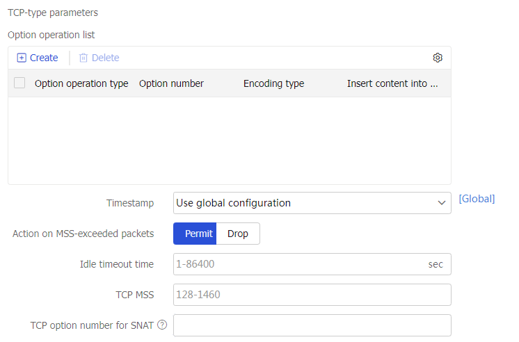
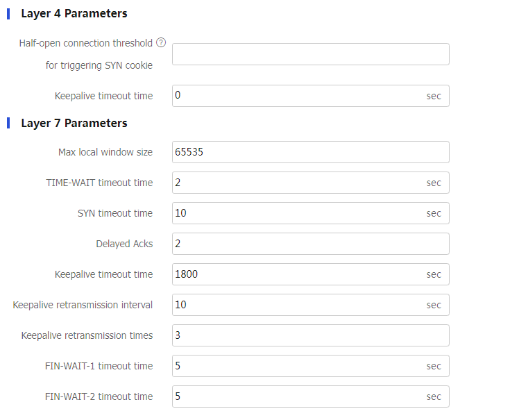
Table-16 TCP parameter configuration items
Item
Description
Option operation list
This feature enables the LB device to insert the client's actual IP address into the specified option in headers of TCP packets sent to the server or remove the specified option.
To create an option operation, click
Create .Insert: Inserts content into the specified option in headers of TCP packets sent to the server.
Remove: Removes the specified option from headers of TCP packets sent to the server.
Option number: Number of the option to be operated.
Encoding type: Select the binary or string encoding mode for the TCP option.
Insert content into TCP options: Enter a string to be inserted into TCP options. You can also specify one or multiple replacement strings including %{is} (client source IP address), %{isl} (length of the source IP address), %{ps} (source port number), and %{psl} (length of the source port number).
Click
OK . The new option operation appears in theOption operation list .
Insert only into data packets
Enable or disable inserting specified content only into data packets.
With this feature enabled, the specified content will be inserted only into data packets. With this feature disabled, the specified content will be inserted into both data packets and handshake packets.
This feature does not take effect if the TCP parameter profile is used by an IP or UDP virtual server, or a TCP virtual server with the operation mode of Layer 4.
Timestamps option
Specify an action to take on the Timestamps option in headers of TCP packets sent to the server. Options include:
Preserve: Preserve the Timestamps option in the headers of TCP packets sent to the server.
Remove: Remove the Timestamps option from the headers of TCP packets sent to the server.
Rewrite: Rewrite the Timestamps option in the headers of TCP packets sent to the server with the Timestamps option value of the LB device.
Use global settings: Use the action specified globally. To view the global settings, click
Global settings to open theObjects >L oad B alancing >Advanced Configuration page.
Action on MSS-exceeded packets
Specify the action to take on the segments that exceed the MSS in the HTTP requests sent by the client.
Permit: Allows the segments to exceed the MSS.
Drop: Discards the segments that exceed the MSS.
Idle timeout time
Specify the idle timeout time for TCP connections.
If no data is transmitted before the idle timeout time expires, the LB device disconnects the TCP connection with the client or server.
TCP MSS
Specify the MSS for the LB device.
TCP option number for SNAT
Specify the number of the TCP option used for SNAT.
The LB device translates the source IP address of packets into the IP address in the specified TCP option.
Layer 4 Parameters-Half-open connection threshold for triggering SYN cookie
Set the half-open connection threshold for triggering SYN cookie.
During the process of establishing a TCP connection between the client and the virtual server, the connection is half-open from the time the virtual server receives the SYN packet until it receives the ACK packet.
This parameter takes effect only when the TCP parameter profile is used by a TCP virtual server with the operation mode of Layer 4.
Layer 4 Parameters-Keepalive timeout time
Set the TCP keepalive packet sending interval for an idle TCP connection.
This parameter takes effect only when the TCP parameter profile is used by a TCP virtual server.
Layer 7 Parameters-Max local window size
Configure the maximum local window size for TCP connections.
Layer 7 Parameters-TIME-WAIT timeout time
Set the TIME_WAIT state timeout time for TCP connections.
A TCP connection is released slowly after it is disconnected, because the TIME_WAIT timer of TCP is long. You can adjust the TIME_WAIT state timeout time.
This parameter takes effect only when the TCP parameter profile is used by an HTTP or HTTPS virtual server.
Layer 7 Parameters-SYN timeout time
Set the SYN packet timeout time for TCP connections. If no SYN-ACK packet is received when the timer expires, the TCP connection is closed.
This parameter takes effect only when the TCP parameter profile is used by an HTTP or HTTPS virtual server.
Layer 7 Parameters-Delayed Acks
Set the number of received TCP data packets for a delayed ACK. With this parameter configured, the device uniformly sends an ACK after receiving the specified number of data packets. This parameter reduces the number of ACK packets and improves network transmission efficiency.
Layer 7 Parameters-Keepalive timeout time
Set the TCP keepalive packet sending interval for an idle TCP connection.
This parameter takes effect only when the TCP parameter profile is used by an HTTP or HTTPS virtual server.
Layer 7 Parameters-Keepalive retransmission interval
Set the TCP keepalive packet retransmission interval.
This parameter takes effect only when the TCP parameter profile is used by an HTTP or HTTPS virtual server.
Layer 7 Parameters-Keepalive retransmission times
Set the TCP keepalive packet retransmission times.
This parameter takes effect only when the TCP parameter profile is used by an HTTP or HTTPS virtual server.
Layer 7 Parameters-FIN-WAIT-1 timeout time
Set the FIN-WAIT-1 state timeout timer for TCP connections.
This parameter takes effect only when the TCP parameter profile is used by an HTTP or HTTPS virtual server.
Layer 7 Parameters-FIN-WAIT-2 timeout time
Set the FIN-WAIT-2 state timeout timer for TCP connections.
This parameter takes effect only when the TCP parameter profile is used by an HTTP or HTTPS virtual server.
Figure-23 HTTP parameter profile settings
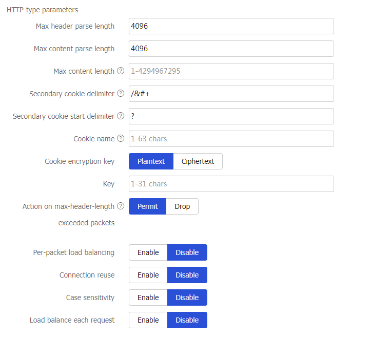
Table-17 HTTP parameter configuration items
Item
Description
Max header parse length
Set the maximum length of HTTP headers that can be parsed.
Max content parse length
Set the maximum length of the HTTP entities that can be parsed.
Max content length
Set the maximum length of the HTTP content permitted by the device. The device drops an HTTP request if its content exceeds the specified maximum length.
Secondary cookie delimiter
Specify the delimiter that separates secondary cookies in URLs, including ! " # ; < > ? [ \ ] ^ ` | : @ & $ + * ' ( ) , /.
Secondary cookie start delimiter
Specify the start delimiter for secondary cookies in URLs, including ! " # ; < > ? [ \ ] ^ ` |.
Cookie name
Specify the cookie to be encrypted by its name, a case-sensitive string.
Cookie encryption key
Specify a key in plaintext or ciphertext form.
Key
Specifies the key, a case-sensitive string.
Action on max-header-length exceeded packets
Specify the action to take on the HTTP requests when their packet headers exceed the maximum length.
Permit: Allows the HTTP requests to pass.
Drop: Discards the HTTP requests.
When the HTTP packet header length exceeds the processing capability of load balancing, the
drop action applies.Per-packet load balancing
Enable or disable per-packet load balancing for HTTP requests.
Connection reuse
Enable or disable connection reuse between the LB device and the server.
Connection reuse allows the LB device to establish connections to the server that can be reused by clients. Because multiple clients can use the same connection, the number of connections between the clients and the server is reduced.
Case sensitivity
Enable or disable case sensitivity for matching character strings. This setting affects the following content:
HTTP header value, HTTP cookie name and value, and URL for matching classes.
Header value, URL, and key value used for generating sticky entries for the HTTP header sticky method.
Cookie name and value and key value used for generating sticky entries for the cookie get sticky method.
Load balance each request
Enable or disable per-request load balancing for HTTP requests.
Figure-24 HTTP compression parameter profile settings
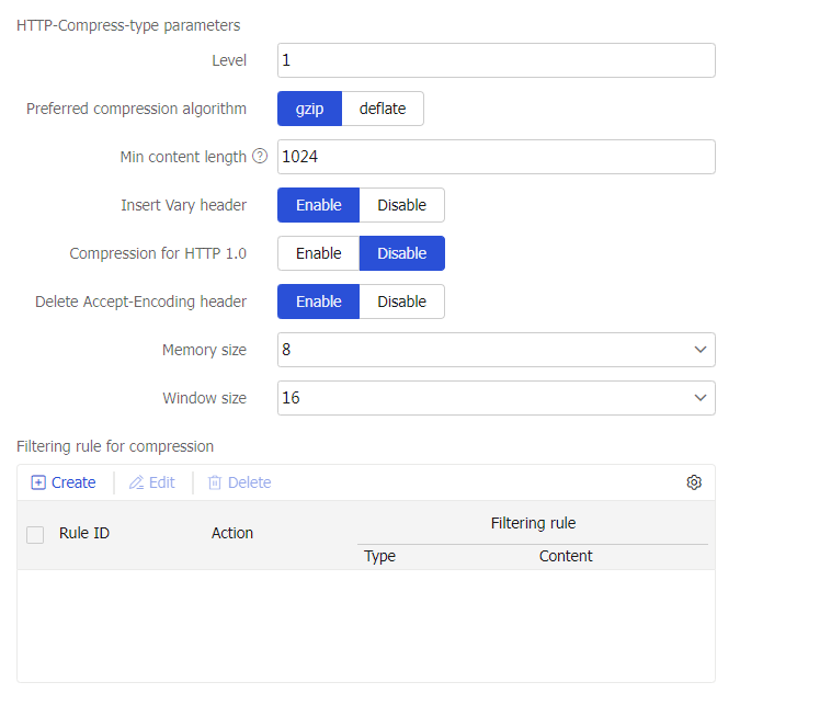
Table-18 HTTP compression parameter configuration items
Item
Description
Level
Set the compression level for response packets. A larger value indicates a lower compression speed and a higher compression ratio.
Preferred compression algorithm
Specify the preferred compression algorithm. If the client request supports the configured compression algorithm, the configured compression algorithm applies. If the client request does not support the configured compression algorithm, the compression algorithm contained in the request applies.
gzip: Specifies the GNU zip compression algorithm.
deflate: Specifies the Deflate compression algorithm.
Min content length
Set the minimum length of HTTP response content for compression. The value 0 indicates that the packet content is always compressed, regardless of the content length.
If an HTTP response packet contains the Content-Length header, the packet content is compressed only when its length reaches the minimum length of HTTP response content for compression. If the HTTP response packet does not contain the Content-Length header, the configuration does not take effect. The packet content is compressed regardless of its length.
Insert Vary header
Enable or disable insertion of the Vary header into HTTP responses.
Enabling this feature inserts the Vary header to HTTP responses and sets the header content to Accept-Encoding before sending them to the client. The setting takes effect regardless of whether the response packets contain the Vary header or whether the packets are compressed.
Compression for HTTP 1.0
Enable or disable compression for responses to HTTP 1.0 requests.
Delete Accept-Encoding header
Enable or disable deletion of the Accept-Encoding header from HTTP requests.
Enabling this feature enables the LB device to delete the Accept-Encoding header from the HTTP request before sending it to the server. If the response packet sent by the server matches the specified match rule, the LB device compresses the packet before sending it to the requesting client. If the HTTP request sent by the client does not contain the Accept-Encoding header, the LB device does not compress the response packet regardless of whether this feature is enabled.
Memory size
Specify the memory size in KB used for compression. The value can only be 1, 2, 4, 8, 16, 32, or 64.
Window size
Specify the window size in KB used for compression. The value can only be 1, 2, 4, 8, 16, or 32.
Filtering rule for compression
Click
Create .Rule ID: Specify the rule ID.
Action: Specify permit to compress matching packets, or specify deny to not compress matching packets.
Type: Specify URL to match URLs in packets, or specify Content-Type to match content types in the Content-Type header of packets.
URL: Specify a regular expression for matching URLs, a case-sensitive string. The string cannot contain question marks (?). This parameter is available only for the URL type.
Content-Type: Specify a regular expression for matching content types, a case-sensitive string. The string cannot contain question marks (?). This parameter is available only for the content type.
Click
OK .
Figure-25 HTTP statistics parameter profile settings
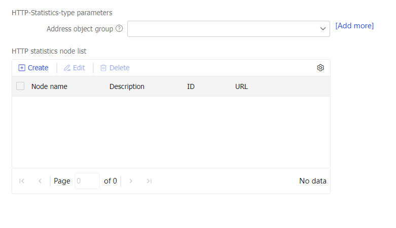
Table-19 HTTP statistics parameter configuration items
Item
Description
Address object group
If HTTP packets match the specified URL and source IP address object group, they are counted based on the source IP address object group. If HTTP packets match the specified URL but do not match the specified source IP address object group, they are counted based on the source IP address.
You can specify a maximum of 1024 source IP address object groups in one HTTP statistics parameter profile.
HTTP statistics node list
Click
Create .Node name: Specify the statistics node name, case insensitive. You can configure a maximum of 256 statistics nodes in one HTTP statistics parameter profile.
Description: Enter a description for the statistics node, case sensitive.
Statistics rule list: List of URL match rules. You can configure a maximum of 256 URL match rules for one statistics node.
ID: Specify the match rule ID.
URL: Specify a URL regular expression. The string cannot contain question marks (?).
Click
OK .
Figure-26 OneConnect parameter profile settings
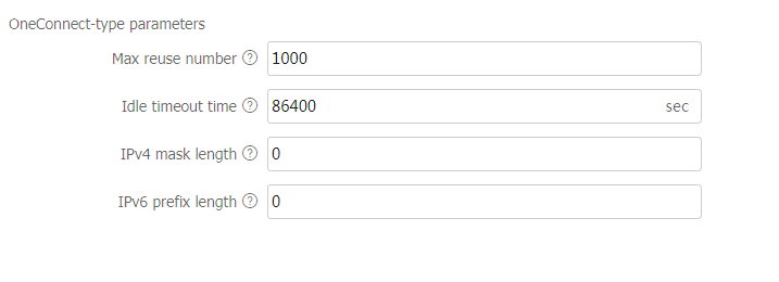
Table-20 OneConnect parameter configuration items
Item
Description
Max reuse number
Set the maximum number of times that a TCP connection can be reused.
After connection reuse is enabled, a TCP connection is not disconnected until the maximum number of reuse times is reached. After the TCP connection is disconnected, new connection requests trigger establishment of a new TCP connection.
Idle timeout time
Set the idle timeout time for TCP connections between the LB device and servers.
The idle timeout time is the amount of time that a TCP connection can stay idle before it is disconnected. After the TCP connection is disconnected, new connection requests trigger establishment of a new TCP connection.
IPv4 mask length
Specify the IPv4 mask length for connection reuse.
This setting limits the network segment of clients that can reuse connections between the LB device and servers. If the client that initiates a connection request is in the same network segment as the idle TCP connection, the idle TCP connection is reused. If the client does not match this requirement, a new TCP connection is established.
IPv6 prefix length
Specify the IPv6 prefix length for connection reuse.
This setting limits the network segment of clients that can reuse connections between the LB device and servers. If the client that initiates a connection request is in the same network segment as the idle TCP connection, the idle TCP connection is reused. If the client does not match this requirement, a new TCP connection is established.
Figure-27 TCP application parameter profile settings
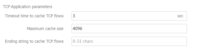
Table-21 TCP application parameter configuration items
Item
Description
TCP buffering period
Specify the buffering period for TCP payload matching.
TCP maximum buffering size
Specify the maximum buffering size.
The device stops buffering traffic when the maximum buffering size is reached.
TCP buffering end string
Configure the TCP buffering end string.
The device stops buffering traffic when it receives the buffering end string.
Figure-28 MySQL parameter profile settings
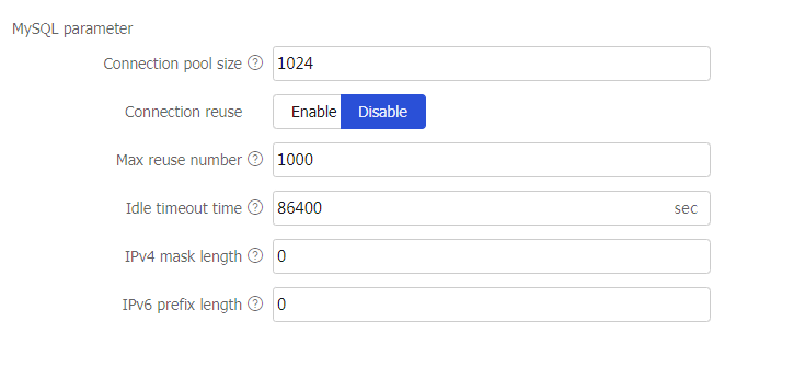
Table-22 MySQL parameter configuration items
Item
Description
Connection pool size
Specify the maximum number of TCP connections that can be stored in a connection pool.
After MySQL data transfer is completed, the TCP connection is stored in a connection pool instead of being closed. For a new connection request, the device selects an available connection from the connection pool before attempting to open a new connection.
Connection reuse
Enable or disable connection reuse.
This feature allows the LB device to establish connections to the server that can be reused by multiple clients.
This feature helps reduce the connections opened between clients and servers.
Max reuse number
Set the maximum number of times that a TCP connection can be reused.
After connection reuse is enabled, a TCP connection is not disconnected until the maximum number of reuse times is reached. After the TCP connection is disconnected, new connection requests trigger establishment of a new TCP connection.
Idle timeout time
Set the idle timeout time for TCP connections between the LB device and servers.
The idle timeout time is the amount of time that a TCP connection can stay idle before it is disconnected. After the TCP connection is disconnected, new connection requests trigger establishment of a new TCP connection.
IPv4 mask length
Specify the IPv4 mask length for connection reuse.
This setting limits the network segment of clients that can reuse connections between the LB device and servers. If a client that initiates a connection request is in the same network segment as the idle TCP connection, the client reuses the idle TCP connection. If the client does not match this requirement, a new TCP connection is established.
IPv6 prefix length
Specify the IPv6 prefix length for connection reuse.
This setting limits the network segment of clients that can reuse connections between the LB device and servers. If a client that initiates a connection request is in the same network segment as the idle TCP connection, the client reuses the idle TCP connection. If the client does not match this requirement, a new TCP connection is established.
Figure-29 Diameter-Session parameter profile settings
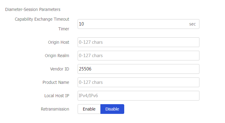
Table-23 Diameter-Session parameter configuration items
Item
Description
Capability exchange timeout timer
Specify the timeout time for capability exchange. When the device establishes a TCP connection with a client or a server, they must exchange Capabilities-Exchange-Request (CER) and Capabilities-Exchange-Answer (CEA) messages. If no CER or CEA messages are exchanged before the timer expires, the device determines that the TCP connection is down and tears down the connection to save system resources.
A Diameter-Session parameter profile takes effect only for Diameter requests.
Original host
Specify the original host name for the device to send to the peer during capability exchange.
The original host name must be a Fully Qualified Domain Name (FQDN), which contains a host name and a domain name.
Original realm
Specify the original realm for the device to send to the peer during capability exchange.
Vendor ID
Specify the vendor ID for the device to send to the peer during capability exchange.
Product name
Specify the product name for the device to send to the peer during capability exchange.
Local host IP
Specify the IP address for the device to send to the peer during capability exchange.
The IP address must be an available IP address that is already configured for an interface on the device.
Retransmission
Enable or disable retransmission of Diameter messages.
This feature enables the device to retransmit Diameter messages to the server farm if it does not receive any response before the retransmission timeout timer expires, ensuring service availability for users.
Retransmission timeout timer
Set the timeout time for retransmitting Diameter messages.
With the retransmission feature enabled, the device retransmits Diameter messages to another real server in the server farm and restarts the timer if it does not receive any response before the timer expires. If the device still does not receive any response before the second timer expires, it determines that the data transmission fails and informs the client that the server is not reachable.
The device can retransmit Diameter messages only once.
Figure-30 HTTP2.0 parameter profile settings
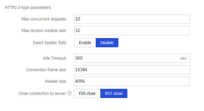
Table-24 HTTP2.0 parameter configuration items
Item
Description
Max concurrent requests
Specify the maximum number of concurrent requests for each TCP connection.
Max receive window size
Specify the maximum receive window size for HTTP/2 packets.
Insert header field
Enable or disable inserting fields into headers of HTTP/2 requests.
Header field name
Specify the header field name to be inserted into HTTP/2 packet headers.
Idle Timeout
Specify the timeout time for idle TCP connections.
Connection frame size
Specify the maximum connection frame size for HTTP/2 packets.
Header size
Specify the header size for HTTP/2 packets.
Close connection to server
FIN close: Close connections to the server by sending FIN packets.
RST close: Close connections to the server by sending RST packets.
This parameter takes effect only when the client sends HTTP/2 requests while the device and real server support only HTTP1.1.
Click
OK . The new parameter profile appears on theParameter Profile page.
Configure an intelligent probe template (optional)
You can configure an HTTP passive, RST, zero-window, custom, or database intelligent probe template to monitor a single server farm member or all members in a server farm.
| Support for intelligent probe template types varies by device model. |

To configure an intelligent probe template:
Select
Polic ies >LB Policy >Server Load Balancing >P robe T emplate s .Click
Create .Create an intelligent probe template.
Figure-31 Intelligent probe template settings
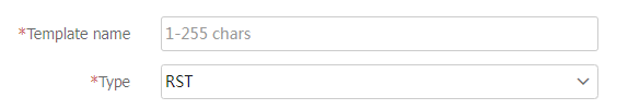
Table-25 Intelligent probe template configuration items
Item
Description
Probe template name
Enter a name for the probe template, case insensitive.
Type
Specify the type for the intelligent probe template:
RST: Monitors the number of RST packets sent by a real server. For information about configuring an RST probe template.
Zero-window: Monitors the number of zero-window packets sent by a real server. For information about configuring a zero-window probe template.
HTTP passive: Monitors the number of abnormal URLs in HTTP response packets. For information about configuring an HTTP passive probe template.
Custom: Monitors the state of real servers by using a custom script file. For information about configuring a custom probe template.
Description
Enter a description for the intelligent probe template.
Figure-32 RST and zero-window probe template settings
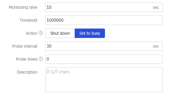
Table-26 RST and zero-window probe template configuration items
Item
Description
Monitoring time
Specify the monitoring time. During the monitoring time, the system counts the number of RST packets or zero-window packets sent by each server farm member in a server farm if an RST or zero-window probe template is specified.
Threshold
Specify the maximum number of RST packets or zero-window packets a real server can send before an action is taken.
Action
Specify the action to take when the RST or zero-window packet threshold is reached.
Shut down: Shuts down a real server.
Set to busy: Places a real server in busy state. The system continues to probe the real server at the probe intervals. If the number of RST or zero-window packets sent does not reach the threshold during the probe interval, the real server is placed back in normal state. If the packet number reaches the threshold, the system probes the real server until the maximum probe times is reached. If the result of every probe reaches the threshold, the system automatically shuts down the real server.
A real server that is shut down due to packet threshold violation or exceeded probe times will be restored to normal state immediately when the intelligent probe template is deleted.
Probe interval
Specify the interval to probe the real server in busy state.
Probe times
Specify the maximum number of times for probing the real server in busy state. The value 0 means that the number of probe times is not limited.
Figure-33 HTTP passive probe template settings
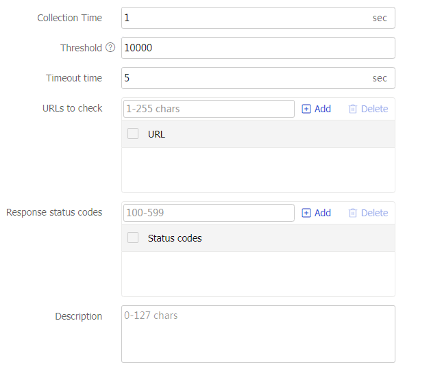
Table-27 HTTP passive probe template configuration items
Item
Description
Monitoring time
Specify the monitoring time. During the monitoring time, the system monitors the responses of matching HTTP requests if an HTTP passive probe template is specified.
Threshold
Specify the maximum number of abnormal URLs in HTTP response packets. If the number of abnormal URLs exceeds the maximum number, the real server is shut down.
Timeout time
Specify the timeout time for the HTTP passive probe template.
The device monitors the responses of HTTP requests with the specified URL. If the response time for an HTTP request exceeds the timeout time, a URL error is recorded.
URLs to check
Configure the URLs to check. The URLs cannot contain question marks (?).
If the device receives an HTTP request with any of the specified URLs, the device monitors the responses of the HTTP request.
A maximum of 10 URLs can be configured for an HTTP passive probe template.
Response status code
Configure the response status codes to check.
If an HTTP response contains any of the specified response status codes, a URL error is recorded.
A maximum of 10 response status codes can be configured for an HTTP passive probe template.
Figure-34 Custom probe template settings
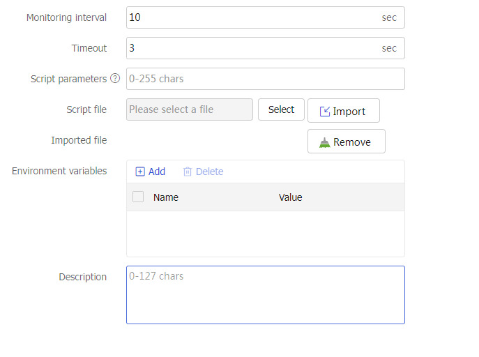
Table-28 Custom probe template configuration items
Item
Description
Monitoring time
Specify the monitoring interval. At the monitoring intervals, the system executes the specified script file.
Timeout time
Specify the timeout time for waiting for responses.
As a best practice, set timeout time to be smaller than the monitoring interval.
Script parameters
Configure script parameters.
When executing a script file, the device transfers the script parameters to the script file.
Multiple space-separated script parameters are supported.
Script file
Select and import a script file.
The device detects the state of real servers according to the detection contents in the script file.
The device supports only script files with the
.py suffix.Environment variables
Configure an environment variable.
You can specify the environment to execute the custom script file by configuring an environment variable.
Click
OK . The new intelligent probe template appears on theP robe T emplate s page.
Configure a global SNAT policy (optional)
A global SNAT policy is used to translate the source IP addresses of packets into the specified IP addresses. You can implement SNAT by configuring a global SNAT policy on the Global SNAT Policy page or by configuring SNAT on the Server Farm page. The SNAT configuration on the Server Farm page has higher priority. A server farm without SNAT configuration uses the global SNAT policy for address translation.
To configure a global SNAT policy:
Select
Polic ies >LB Policy >Server Load Balancing >Global SNAT Policies .Click
Create .Create a global SNAT policy.
Figure-35 Global SNAT policy settings
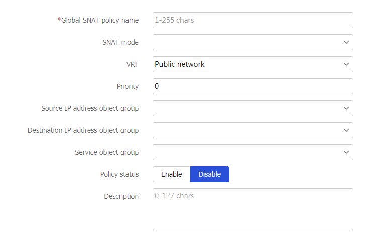
Table-29 Global SNAT policy configuration items
Item
Description
Global SNAT policy name
Enter a name for the global SNAT policy, case insensitive.
SNAT mode
Select an SNAT mode.
Only the SNAT pool mode is supported. This mode translates the source IP address into an IP address in the specified SNAT address pool.
SNAT pool name
Select an existing SNAT pool or create an SNAT pool.
VRF
Specify the VPN instance to which the global SNAT policy belongs.
Priority
Set the priority for the global SNAT policy.
You can configure multiple global SNAT policies with different priorities. They are matched in descending order of priority values.
Source IP address object group
Specify a source IP address object group for address translation. The device performs SNAT on only packets with a matching source IP address.
Destination IP address object group
Specify a destination IP address object group for address translation. The device performs SNAT on only packets with a matching destination IP address.
Service object group
Specify a service object group for address translation. The device performs SNAT on only packets with a matching service.
Policy status
Enable or disable the global SNAT policy.
Description
Enter a description for the global SNAT policy.
Click
OK . The new global SNAT policy appears on theG l obal SNAT Policy page.
Appendix Fast log output content
Fast log output content supported by IP, TCP, UDP, HTTP and HTTPS virtual servers
Specify the content to be output by using the fast log output feature. You can enter multiple variables separated by semicolons, for example,
IP, TCP, and UDP virtual servers support configuring the following variables:
%{is} —Source IP address on the client side.%{ps} —Source port number on the client side.%{id} —Destination IP address on the client side.%{pd} —Destination port number on the client side.%{sis} —Source IP address on the server side.%{sps} —Source port number on the server side.%{sid} —Destination IP address on the server side.%{spd} —Destination port number on the server side.%{vsn} —Virtual server name.%{sfn} —Server farm name.%{protocol} —Protocol type of traffic.%{tmfirst} —Timestamp of the first packet in the current flow, in GMT format.%{tmlast} —Timestamp of the last packet in the current flow, in GMT format.%{tmduration} —Duration of the current flow (time between the first packet and last packet).%{cbytes_recv} —Total data size received from the client (of the entire session).%{cbytes_sent} —Total data size sent to the client (of the entire session).%{sbytes_recv} —Total data size received from the server (of the entire session).%{sbytes_sent} —Total data size sent to the server (of the entire session).
HTTP and HTTPS virtual servers support configuring the following variables:
%{is} —Source IP address on the client side.%{ps} —Source port number on the client side.%{id} —Destination IP address on the client side.%{pd} —Destination port number on the client side.%{sis} —Source IP address on the server side.%{sps} —Source port number on the server side.%{sid} —Destination IP address on the server side.%{spd} —Destination port number on the server side.%{vsn} —Virtual server name.%{sfn} —Server farm name.%{reqtmstamp} —HTTP request timestamp in GMT format.%{reqtime} —HTTP request timestamp in CST format.%{uri} —HTTP URI.%{ver} —HTTP version number.%{args} —HTTP access parameters.%{method} —HTTP request method.%{xff} —IP address of XFF (X-Forwarded-For).%{ctype} —Content-Type field in HTTP requests.%{clen} —Content-Length field in HTTP requests.%{ref} —Referer header field in HTTP requests.%{ua} —User-Agent header field in HTTP requests.%{host} —Host header field in HTTP requests.%{path} —Path in HTTP requests.%{reqsz} —HTTP request size in bytes.%{reqtm} —HTTP request duration in milliseconds. The duration is from the time when the device receives an HTTP request to the time when the device receives the HTTP response.%{reqtm_s} —HTTP request duration in seconds. The duration is from the time when the device receives an HTTP request to the time when the device receives the HTTP response.%{conntm_s} —HTTP connection duration in seconds. The duration is from the time when the device establishes an HTTP connection with the client to the time when the device sends the HTTP response.%{repstatus} —Status code of HTTP response packets.%{rspclen} —Content-Length field in HTTP responses.%{reqsz} —HTTP response size in bytes.%{rsptm} —HTTP response duration in milliseconds. The duration is from the time when the device receives an HTTP response to the time when the device finishes sending out the HTTP response.%{stscode} —HTTP response status code.%{reqbsz} —Body size of HTTP requests, in bytes.%{rspbsz} —Body size of HTTP responses, in bytes.%{rspsntbsz} —Body size of HTTP responses sent from the device to the client, in bytes.%{rspctype} —Content-Type field in HTTP responses.%{x509v} —Certificate version.%{x509sigalgo} —Certificate algorithm.%{x509issuer} —Certificate issuer.%{x509before} —Certificate effective time.%{x509after} —Certificate expiration time.%{x509sub} —Certificate subject.%{dnc} —Country.%{dns} —State/Province.%{dnl} —City.%{dno} —Company.%{dncn} —Common name.%{cookie_ cookie-name } —HTTP cookie name, case sensitive. For example,%{cookie_cookie1} . The cookie name cannot contain brackets ({ }, ( ),[ ], < >), at sign (@), comma (,), semicolon (;), colon (:), backslash (\), quotation mark ("), slash (/), question mark (?), equal sign (=), space character (SP), or horizontal tab (HT). Additionally, the cookie name cannot contain ASCII codes that are less than or equal to 31 or greater than or equal to 127. You can specify multiple cookies for the device.%{reqhdr_ header-name } —Name of the HTTP request packet header, case insensitive. For example,%{reqhdr_Host} . The header name cannot contain brackets ({ }, ( ),[ ], < >), at sign (@), comma (,), semicolon (;), colon (:), backslash (\), quotation mark ("), slash (/), question mark (?), equal sign (=), space character (SP), or horizontal tab (HT). Additionally, the header name cannot contain ASCII codes that are less than or equal to 31 or greater than or equal to 127. You can specify multiple header names for the device, for example,%{reqhdr_Host};%{reqhdr_Connection} .%{rsphdr_ header-name } —Name of the HTTP response packet header, case insensitive. For example,%{rsphdr_Content-Length} . The header name cannot contain brackets ({ }, ( ),[ ], < >), at sign (@), comma (,), semicolon (;), colon (:), backslash (\), quotation mark ("), slash (/), question mark (?), equal sign (=), space character (SP), or horizontal tab (HT). Additionally, the header name cannot contain ASCII codes that are less than or equal to 31 or greater than or equal to 127. You can specify multiple header names for the device, for example,%{rsphdr_Server};%{rsphdr_Expires} .%{reqbody_ content-type_size } —Body information of the HTTP request packet. You can customize the Content-Type and length (size ) values for the body information. The value range for the size value is 1 to 131072 bytes. If you do not specify thesize value, the default setting 512 bytes applies. If the actual body length exceeds the specified size, the system outputs log for only the specified length of the body information. For example, if the actual body length is 1024 bytes and you configure%{reqbody_content-type_512};%{reqbody_content-type_2048} , the system outputsxxxxx (log length of 512 bytes );yyyy (log length of 1024 bytes ).The following table shows the input formats for the Content-Type value in a standard packet header.
Table-30 Input formats for the Content-Type value in a standard packet header
Input format
Content-Type value in a standard packet header
axwfu
application/x-www-form-urlencoded
ajson
application/json
acejson
application/cloudevents+json
acebjson
application/cloudevents-batch+json
ayaml
application/yaml
axml
application/xml
asxml
application/soap+xml
multiformdata
multipart/form-data
multirelated
multipart/related
tplain
text/plain
tcsv
text/csv
txml
text/xml
thtml
text/html
axhtmlxml
application/xhtml+xml
To specify multiple Content-Type values, use vertical bars (|) to separate them. For example,
%{reqbody_axwfu|ajson|multirelated_512} .%{rspbody_content-type_size} —Body information of the HTTP response packet. You can customize the Content-Type and maximum length (size ) values for the body information. Configure the content-type and size values in the same way%{reqbody_content-type_size} is configured. (Details not shown.)