IPsec diagnosis
This help contains the following topics:
Introduction
IPsec diagnosis can detect the status of IPsec connections. If the diagnosed IPsec connection is faulty, you can use the diagnosis results to check for misconfigurations and find possible causes.
The following diagnosis modes are supported:
Data flow—The system obtains the IPsec policy according to the specified data flow to initiate diagnosis of IPsec with the peer.
Interface—The system obtains the IPsec policy according to the specified interface to initiate diagnosis of IPsec with the peer.
IP address—The system starts diagnosis of IPsec with the peer (specified by its IP address) after the peer initiates the IPsec connection.
Table-1 IPsec diagnosis items
Item | Description |
IPsec peer reachability | Determines whether a route to the peer IP address exists in the routing table. |
Interface state | Determines the physical layer status and IP protocol layer status of the interface. The system determines the interface to check according to the diagnosis mode:
|
If IPsec policy applied on interface | Determines whether an IPsec policy is applied to the interface. |
If ACL rule in IPsec policy matches specified flow | This item is available only for IPsec diagnosis in data flow mode. Check the IPsec policy configuration if this item displays No. |
If ACL rule can match flow on the interface | This item is available only for IPsec diagnosis in interface mode. This item shows whether the ACL used in the IPsec policy contains permit rules to identify traffic that needs IPsec protection. The permit rules are required for IPsec to operate correctly. |
IPsec policy configuration check | Checks if the IPsec policy configuration is complete.
|
IKE negotiation result | If the IKE negotiation is operating correctly, this item displays IKE negotiation succeeded or IKE SA already exists. Any other information indicates that the IKE negotiation is faulty. Follow the instructions to find the cause. For example, verify that the local end and peer end have correct and matching IKE profiles. |
IPsec negotiation result | If the IPsec negotiation is operating correctly, this item displays IPsec negotiation succeeded or IPsec tunnel already exists. Any other information indicates that the IPsec negotiation is faulty. Follow the instructions to find the cause. For example, verify that the local end and peer end have correct and matching IPsec policy settings. |
vSystem support information
Support of non-default vSystems for this feature depends on the device model. This feature is available on the Web interface only if it is supported.
Restrictions and guidelines
In data flow mode, specify the source and destination IP addresses of the data flow before IPsec encapsulation in the Source IP address and Destination IP address fields.
In data flow and interface modes, IPsec diagnosis works only if the device can find an IPsec policy to initiate an IPsec connection. IPsec policies configured by using IPsec policy templates cannot initiate IPsec connections, so they are ignored during IPsec diagnosis in data flow or interface mode.
An IPsec diagnosis in data flow or interface mode can last up to 20 minutes. After the timer expires, the diagnosis stops and the completed diagnosis items are displayed.
An IPsec diagnosis in IP address mode starts when it detects an IPsec connection initiated by the peer and stops when it finishes diagnosis for the IPsec connection.
Only one IPsec diagnosis can run at the same time.
IPsec diagnosis is available only on the IPv4 network.
The device supports IPsec policy-based IPsec diagnosis but does not support IPsec profile-based IPsec diagnosis.
The VRF is the VPN instance of the interface where the IPsec policy is applied.
Configure IPsec diagnosis
Prerequisites
Complete the following tasks before you configure this feature:
Assign IP addresses to interfaces on the Network > Interface Configuration > Interfaces page.
Configure routes on the Network > Routing page. Make sure the routes are available.
Create security zones on the Network > Security Zones page.
Add interfaces to security zones. You can add interfaces to a security zone on the Security Zones page or select a security zone for an interface on the Interfaces page.
Configure security policies to permit the target traffic on the Policies > Security Policies page.
Configure IPsec diagnosis settings
Click the System tab.
Select Diagnosis Center > IPsec Diagnosis.
Configure IPsec diagnosis parameters.
Figure-1 Configuring IPsec diagnosis parameters
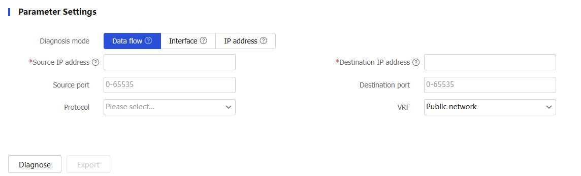
Table-2 IPsec diagnosis configuration items
Item
Description
Diagnosis mode
Specify the diagnosis mode. Options include:
Data flow—Obtains the IPsec policy according to the specified data flow to initiate diagnosis of IPsec with the peer.
Interface—Obtains the IPsec policy according to the specified interface to initiate diagnosis of IPsec with the peer.
IP address—Starts IPsec diagnosis after receiving a packet from the specified peer IP address.
Source IP address
Source IP address of the data flow before IPsec encapsulation.
Destination IP address
Destination IP address of the data flow before IPsec encapsulation.
Source port
Source port of the data flow before IPsec encapsulation.
Destination port
Destination port of the data flow before IPsec encapsulation.
Protocol
Protocol used by the data flow before IPsec encapsulation.
VRF
VRF to which the data flow before IPsec encapsulation belongs.
Policy-applied interface
Interface where the IPsec policy is applied.
Peer IP address
Peer IP address of the IPsec tunnel, namely the peer IP address of the data flow after IPsec encapsulation.
VRF
VRF to which the peer IP address belongs.
Click Diagnose and view diagnosis results.