Interface
This help contains the following topics:
Introduction
Your device supports the following types of Ethernet interfaces:
Layer 2 Ethernet interface —Physical Ethernet interface operating at the data link layer (Layer 2) to switch packets.Layer 3 Ethernet interface —Physical Ethernet interface operating at the network layer (Layer 3) to route packets. You can assign an IP address to a Layer 3 Ethernet interface.Layer-configurable Ethernet interface —Physical Ethernet interface that can be configured to operate in bridge mode as Layer 2 Ethernet interfaces or in route mode as Layer 3 Ethernet interfaces.Layer 3 Ethernet subinterface —Logical interface operating at the network layer. You can assign an IP address to a Layer 3 Ethernet subinterface. To enable a Layer 3 Ethernet interface to transport packets for multiple VLANs, you must create Layer 3 subinterfaces on the Layer 3 Ethernet interface.Layer 2 aggregate interface —Logical interface that uniquely corresponds to a Layer 2 aggregation group. This type of interface is used for implementing Layer 2 link aggregation.Layer 3 aggregate interface —Logical interface that uniquely corresponds to a Layer 3 aggregation group. This type of interface can be assigned IP addresses and is used for implementing Layer 3 link aggregation.Layer 3 aggregate subinterface —Logical interface that can be assigned IP addresses. This type of interface is used to enable a Layer 3 aggregate interface to send and receive VLAN tagged packets.Loopback interface —Logical interface that can be assigned IP addresses. After a loopback interface is created, the physical layer state of the loopback interface is always up unless the loopback interface is manually shut down.VLAN interface —Logical interface. Each VLAN corresponds to one VLAN interface. After an IP address is assigned to a VLAN interface, the IP address can be used as the gateway address for network devices in the VLAN, and the VLAN interface can forward packets destined for another IP subnet at Layer 3. For more information about VLAN interfaces, see "VLAN."SSL VPN interface —Logical interface that can be assigned IP addresses. When a user accesses an SSL VPN gateway through the IP access method, the gateway uses this interface to communicate with the client. For more information about SSL VPN interfaces, see "SSL VPN."Reth interface —Logical interface that can be assigned IP addresses. A Reth interface uses two member interfaces to ensure link availability. For more information about Reth interfaces, see "Hot backup."Reth subinterface —Logical interface that can be assigned IP addresses. This type of interface is used to enable a Reth interface to send and receive Layer 2 VLAN-tagged packets. For more information about Reth subinterfaces, see "Hot backup."
IPv4 address
IP address representation and classes
IP addressing uses a 32-bit address to identify each host on an IPv4 network. To make addresses easier to read, they are written in dotted decimal notation, each address being four octets in length. For example, address 00001010000000010000000100000001 in binary is written as 10.1.1.1.
Each IP address breaks down into the following sections:
Net ID —Identifies a network. The first several bits of a net ID, known as the class field or class bits, identify the class of the IP address.Host ID —Identifies a host on a network.
IP addresses are divided into five classes, as shown in Table-1. The first three classes are most commonly used.
Table-1 IP address classes and ranges
Class | Address range | Remarks |
A | 0.0.0.0 to 127.255.255.255 | The IP address 0.0.0.0 is used by a host at startup for temporary communication. This address is never a valid destination address. Addresses starting with 127 are reserved for loopback test. Packets destined to these addresses are processed locally as input packets rather than sent to the link. |
B | 128.0.0.0 to 191.255.255.255 | N/A |
C | 192.0.0.0 to 223.255.255.255 | N/A |
D | 224.0.0.0 to 239.255.255.255 | Multicast addresses. |
E | 240.0.0.0 to 255.255.255.255 | Reserved for future use, except for the broadcast address 255.255.255.255. |
Subnetting and masking
Subnetting divides a network into smaller networks called subnets by using some bits of the host ID to create a subnet ID.
Masking identifies the boundary between the host ID and the combination of net ID and subnet ID.
Each subnet mask comprises 32 bits that correspond to the bits in an IP address. In a subnet mask, consecutive ones represent the net ID and subnet ID, and consecutive zeros represent the host ID.
Before being subnetted, Class A, B, and C networks use these default masks (also called natural masks): 255.0.0.0, 255.255.0.0, and 255.255.255.0, respectively.
Subnetting increases the number of addresses that cannot be assigned to hosts. Therefore, using subnets means accommodating fewer hosts.
For example, a Class B network without subnetting can accommodate 1022 more hosts than the same network subnetted into 512 subnets.
Without subnetting —65534 (216 – 2) hosts. (The two deducted addresses are the broadcast address, which has an all-one host ID, and the network address, which has an all-zero host ID.)With subnetting —Using the first nine bits of the host-id for subnetting provides 512 (29 ) subnets. However, only seven bits remain available for the host ID. This allows 126 (27 – 2) hosts in each subnet, a total of 64512 (512 × 126) hosts.
IPv6 address
IPv6, also called IP next generation (IPng), was designed by the IETF as the successor to IPv4. One significant difference between IPv6 and IPv4 is that IPv6 increases the IP address size from 32 bits to 128 bits.
IPv6 address format
An IPv6 address is represented as a set of 16-bit hexadecimals separated by colons (:). An IPv6 address is divided into eight groups, and each 16-bit group is represented by four hexadecimal numbers, for example, 2001:0000:130F:0000:0000:09C0:876A:130B.
To simplify the representation of IPv6 addresses, you can handle zeros in IPv6 addresses by using the following methods:
The leading zeros in each group can be removed. For example, the above address can be represented in a shorter format as 2001:0:130F:0:0:9C0:876A:130B.
If an IPv6 address contains one or more consecutive groups of zeros, they can be replaced by a double colon (::). For example, the above address can be represented in the shortest format as 2001:0:130F::9C0:876A:130B.
An IPv6 address consists of an address prefix and an interface ID, which are equivalent to the network ID and the host ID of an IPv4 address.
An IPv6 address prefix is written in IPv6-address/prefix-length notation. The prefix-length is a decimal number indicating how many leftmost bits of the IPv6 address are in the address prefix.
IPv6 address type
IPv6 addresses include the following types:
Unicast address —An identifier for a single interface, similar to an IPv4 unicast address. A packet sent to a unicast address is delivered to the interface identified by that address.Multicast address —An identifier for a set of interfaces (typically belonging to different nodes), similar to an IPv4 multicast address. A packet sent to a multicast address is delivered to all interfaces identified by that address. Broadcast addresses are replaced by multicast addresses in IPv6.Anycast address —An identifier for a set of interfaces (typically belonging to different nodes). A packet sent to an anycast address is delivered to the nearest interface among the interfaces identified by that address. The nearest interface is chosen according to the routing protocol's measure of distance.
The type of an IPv6 address is designated by the first several bits, called the format prefix.
Table-2 Mappings between address types and format prefixes
Type | Format prefix (binary) | IPv6 prefix ID | Description | |
Unicast address | Unspecified address | 00...0 (128 bits) | ::/128 | It cannot be assigned to any node. Before acquiring a valid IPv6 address, a node fills this address in the source address field of IPv6 packets. The unspecified address cannot be used as a destination IPv6 address. |
Loopback address | 00...1 (128 bits) | ::1/128 | It has the same function as the loopback address in IPv4. It cannot be assigned to any physical interface. A node uses this address to send an IPv6 packet to itself. | |
Link-local address | 1111111010 | FE80::/10 | Used for communication among link-local nodes for neighbor discovery and stateless autoconfiguration. Packets with link-local source or destination addresses are not forwarded to other links. | |
Global unicast address | Other forms | N/A | Equivalent to public IPv4 addresses, global unicast addresses are provided for Internet service providers. This type of address allows for prefix aggregation to restrict the number of global routing entries. | |
Multicast address | 11111111 | FF00::/8 | N/A | |
Anycast address | Anycast addresses use the unicast address space and have the identical structure of unicast addresses. | N/A | ||
IEEE EUI-64 address-based interface identifiers
An interface identifier is 64 bits long and uniquely identifies an interface on a link.
On an IEEE 802 interface (such as a VLAN interface), the interface identifier is derived from the link-layer address (typically a MAC address) of the interface. The MAC address is 48 bits long.
To obtain an EUI-64 address-based interface identifier, follow these steps:
Insert the 16-bit binary number 1111111111111110 (hexadecimal value of FFFE) behind the 24th high-order bit of the MAC address.
Invert the universal/local (U/L) bit (the seventh high-order bit). This operation makes the interface identifier have the same local or global significance as the MAC address.
On a tunnel interface, the lower 32 bits of the EUI-64 address-based interface identifier are the source IPv4 address of the tunnel interface. The higher 32 bits of the EUI-64 address-based interface identifier of an ISATAP tunnel interface are 0000:5EFE, whereas those of other tunnel interfaces are all zeros.
On an interface of another type (such as a serial interface) the EUI-64 address-based interface identifier is generated randomly by the device.
Link aggregation
Ethernet link aggregation bundles multiple physical Ethernet links into one logical link (called an aggregate link). Link aggregation provides the following benefits:
Increased bandwidth beyond the limits of a single individual link. In an aggregate link, traffic is distributed across the member ports.
Improved link reliability. The member ports dynamically back up one another. When a member port fails, its traffic is automatically switched to other member ports.
Aggregation groups
Each link aggregation is represented by a logical aggregate interface. Each aggregate interface has an automatically created aggregation group, which contains member ports to be used for aggregation. The type and number of an aggregation group are the same as its aggregate interface.
An aggregate interface can be one of the following types:
Layer 2 —The member ports in a Layer 2 aggregation group can only be Layer 2 Ethernet interfaces.Layer 3 —The member ports in its Layer 3 aggregation group can only be Layer 3 Ethernet interfaces.
The port rate of an aggregate interface equals the total rate of its Selected member ports. Its duplex mode is the same as that of the Selected member ports.
Aggregation states of member ports in an aggregation group
A member port in an aggregation group might be placed in one of the following aggregation states:
Selected —A Selected port can forward traffic.Unselected —An Unselected port cannot forward traffic.
Operational key
When aggregating ports, the system automatically assigns each port an operational key based on port information, such as port rate and duplex mode. Any change to this information triggers a recalculation of the operational key.
In an aggregation group, all Selected ports have the same operational key.
Attribute configuration
To become a Selected port, a member port must have the same attribute configuration as the aggregate interface. Table-3 describes the attribute configuration.
Table-3 Attribute configuration
Feature | Attribute configuration |
Port isolation | Membership of the port in an isolation group. Isolation group number. |
VLAN | VLAN attribute settings:
VLAN tagging mode. |
Link aggregation modes
An aggregation group operates in one of the following modes:
How static link aggregation works
Reference port selection process
When setting the aggregation states of the ports in an aggregation group, the system automatically chooses a member port as the reference port. A Selected port must have the same operational key and attribute configurations as the reference port.
All up member ports with the same attribute configuration as the aggregate interface are candidate reference ports. The system chooses a reference port from among the candidate reference ports based on the following tiebreakers in descending order:
Highest port priority.
Full duplex and high speed.
Full duplex and low speed.
Half duplex and high speed.
Half duplex and low speed.
Port that used to be Selected.
Lowest numbered port.
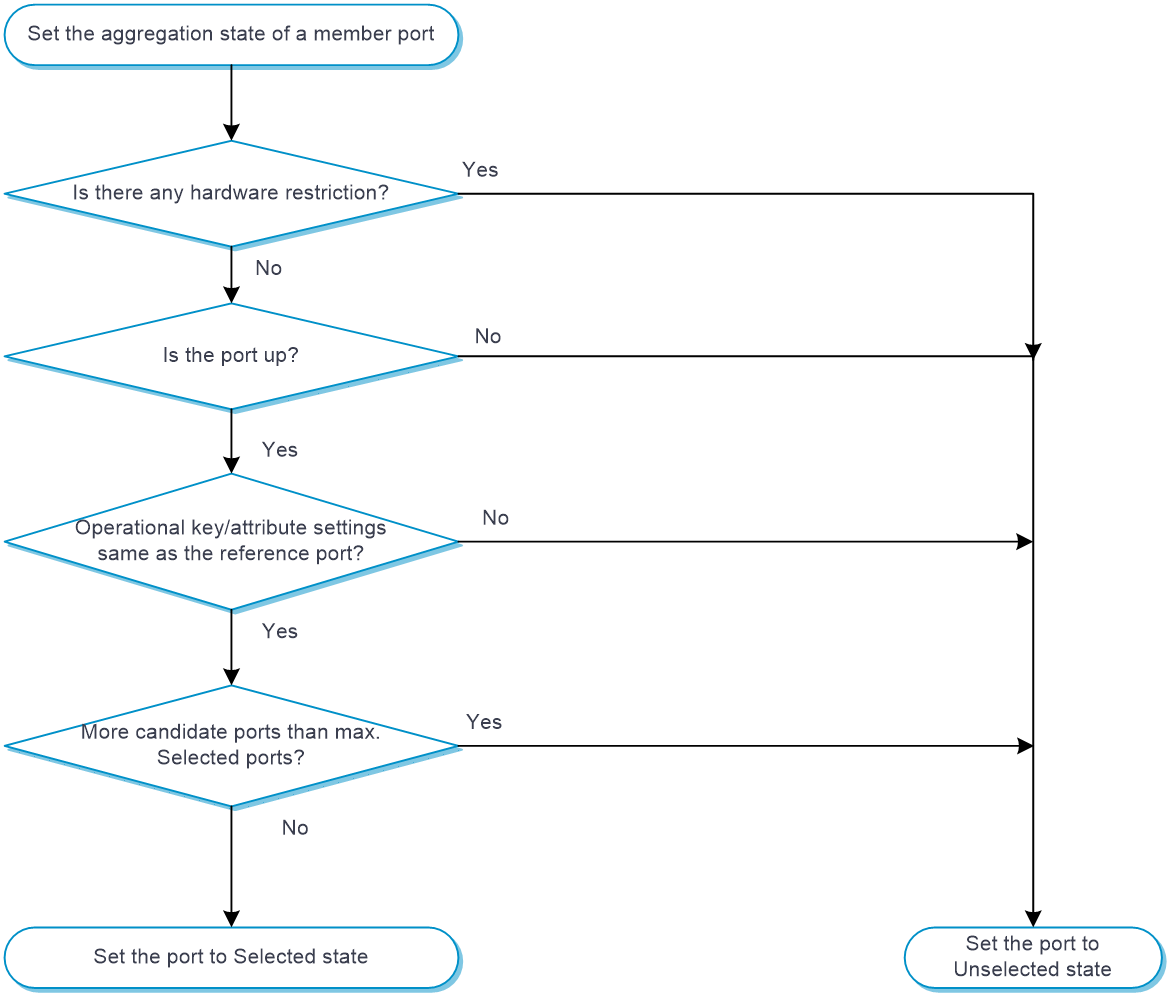
Setting the aggregation state of each member port
After the reference port is chosen, the system sets the aggregation state of each member port in the static aggregation group.
Figure-1 Setting the aggregation state of a member port in a static aggregation group
How dynamic link aggregation works
Dynamic aggregation is an implementation of IEEE 802.3ad Link Aggregation Control Protocol (LACP).
LACP uses LACPDUs to exchange aggregation information between LACP systems. Each member port in a dynamic aggregation group exchanges aggregation information with its peer and compares the received information with information received on the other member ports. Based on the exchanged aggregation information, the two systems reach an agreement on which ports are placed in Selected state.
The system chooses a reference port from the member ports in up state. A Selected port must have the same operational key and attribute configurations as the reference port.
The local system (the actor) and the peer system (the partner) negotiate a reference port by using the following workflow:
The two systems determine the system with the smaller system ID.
A system ID contains the LACP system priority and the system MAC address.
The two systems compare their LACP priority values.
The lower the LACP priority, the smaller the system ID. If the LACP priority values are the same, the two systems proceed to the next step.
The two systems compare their MAC addresses.
The lower the MAC address, the smaller the system ID.
The system with the smaller system ID chooses the port with the smallest port ID as the reference port.
A port ID contains a port priority and a port number. The lower the port priority, the smaller the port ID.
The system chooses the port with the lowest priority value as the reference port.
If the ports have the same priority, the system proceeds to the next step.
The system compares their port numbers.
The smaller the port number, the smaller the port ID.
The port with the smallest port number and the same attribute configurations as the aggregate interface is chosen as the reference port.
Setting the aggregation state of each member port
After determining the reference port, the system with the smaller system ID sets the state of each member port on its side.
The system with the greater system ID detects the aggregation state changes on the peer system. Then, it sets the aggregation state of local member ports to be the same as their peer ports.
Figure-2 Setting the state of a member port in a dynamic aggregation group

A comparison of static link aggregation and dynamic link aggregation
The following are differences between static and dynamic link aggregation modes:
Static —A static aggregation is stable. The peer systems do not negotiate the aggregation states of their member ports. The aggregation state of a member port does not change automatically after the aggregation state of its peer port changes.Dynamic —The local system and the peer system automatically negotiate and maintain the aggregation states of the member ports.
VLAN termination
About VLAN termination
VLAN termination typically processes packets that include VLAN tags. A VLAN termination-enabled interface performs the following tasks when receiving a VLAN-tagged packet:
Assigns the packet to an interface according to its VLAN tags.
Removes the VLAN tags of the packet.
Delivers the packet to Layer 3 forwarding or other processing pipelines.
Before sending the packet, the VLAN termination-enabled interface determines whether to add new VLAN tags to the packet, based on the VLAN termination type.
VLAN termination types
Types of packets to be terminated on the interface | Tags of outgoing packets on the interface | |
Dot1q termination | The packets must meet both of the following requirements:
| Single-tagged |
Untagged termination | Untagged packets. | Untagged |
Default termination | Packets that cannot be processed on any other subinterfaces of the same main interface. | Untagged |
VLAN termination mechanism
VLAN interfaces and subinterfaces, such as Layer 3 Ethernet subinterfaces and Layer 3 aggregate subinterfaces, can terminate the following packets:
Packets whose outermost VLAN IDs match the configured values.
Packets whose outermost two layers of VLAN IDs match the configured values.
A VLAN interface terminates only the packets whose outermost VLAN ID is the same as the VLAN interface number. For example, VLAN-interface 10 terminates only the packets with the outermost VLAN tag 10.
A main interface does not terminate VLAN-tagged packets (for example, Layer 3 Ethernet interface or Layer 3 aggregate interface). To terminate VLAN-tagged packets, create subinterfaces for the main interface.
Subinterfaces of the same main interface can use different types of VLAN termination. To process received packets, the system selects a subinterface based on the following VLAN termination types in descending order of priority:
Dot1q termination or support for Dot1q termination by default.
Untagged termination.
Default termination.
If none of these VLAN termination types applies, the main interface processes the packets.
If default termination is enabled on a subinterface of an interface, packets are processed by the subinterface instead of the main interface.
When a main interface is bound to a VLAN interface, the main interface processes VLAN-tagged packets according to the VLAN termination configuration of the VLAN interface.
Restrictions and guidelines
When an interface is shut down, all services that need to pass through the device are interrupted on the network connected to the interface.
You must set the same aggregation mode at the two ends of an aggregate link.
For a successful static aggregation, make sure the ports at both ends of each link are in the same aggregation state.
Deleting a Layer 2 aggregate interface also deletes its Layer 2 aggregation group. At the same time, the member ports of the aggregation group, if any, leave the aggregation group.
For a link aggregation, attribute configurations are configurable only on the aggregate interface and are automatically synchronized to all member ports. The configuration synchronized from the aggregate interface is retained on the member ports even after the aggregate interface is deleted.
You cannot assign an interface to a Layer 3 aggregation group if that interface is the member of a Reth interface or is on a redundancy group node.
Make sure the ports at both ends of a dynamic link aggregation are assigned to the correct aggregation group. The two ends can automatically negotiate the aggregation state of each member port.
vSystem support information
Support of non-default vSystems for this feature depends on the device model. This feature is available on the Web interface only if it is supported.
Configure interfaces
Prerequisites
Complete the following tasks before you configure this feature:
Assign IP addresses to interfaces on the
Network >Interface Configuration >Interfaces page.Configure routes on the
Network >Routing page. Make sure the routes are available.Create security zones on the
Network >Security Zones page.Add interfaces to security zones. You can add interfaces to a security zone on the
Security Zones page or select a security zone for an interface on theInterfaces page.Configure security policies to permit the target traffic on the
Policies >Security Policies page.
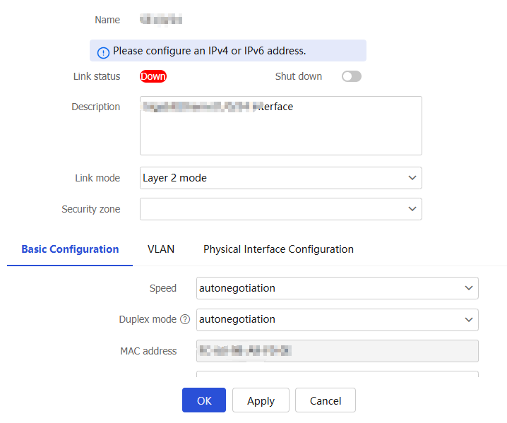
Configure Layer 3 interfaces
A Layer 3 Ethernet interface is a physical interface that operates at the network layer. It allows you to configure an IP address and can forward received packets at Layer 3.
To configure a Layer 3 interface:
Click the
Network tab.In the navigation pane, select
Interface Configuration >Interfaces .On the
Interfaces page, select the Layer 3 interface you want to edit, and then clickEdit for that interface to access theModify Interface Settings page.Figure-3 Modifying the settings of a Layer 3 interface
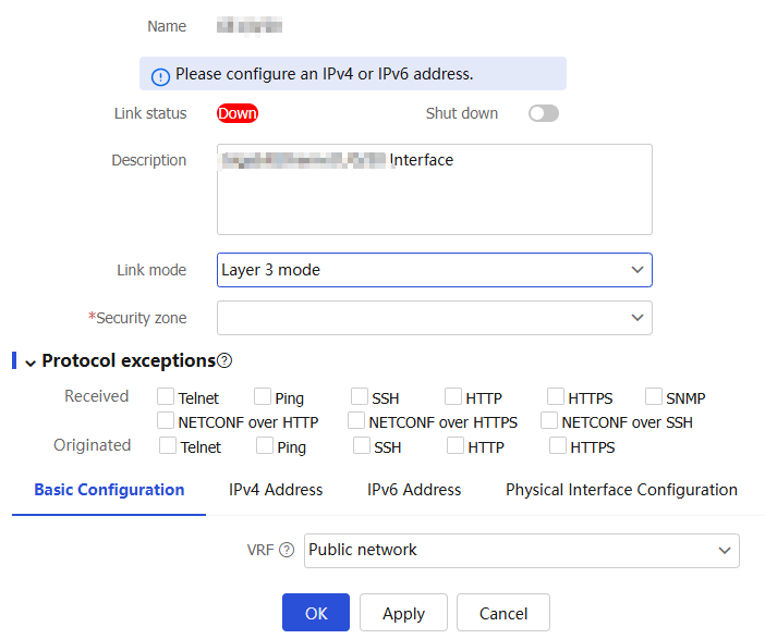
From the
Link mode list, selectLayer 3 mode . Then, configure the following settings for the interface:Figure-4 Basic configuration
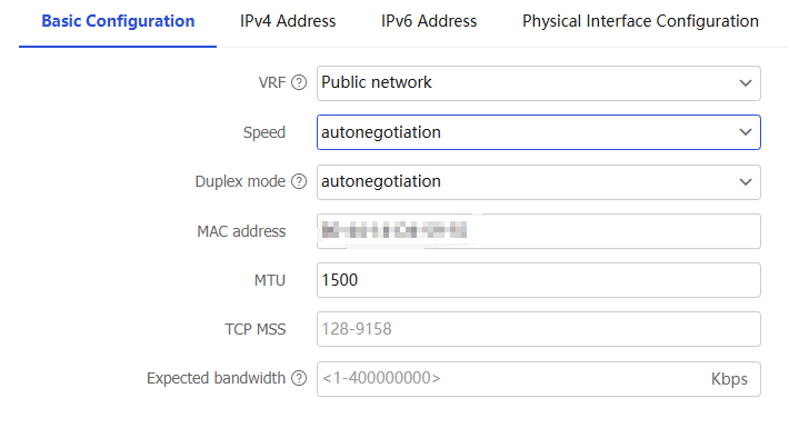
Figure-5 IPv4 address configuration
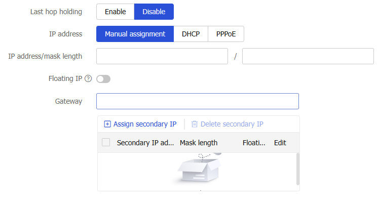
Figure-6 IPv6 address configuration
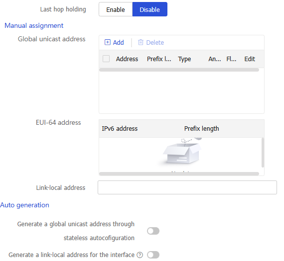
Figure-7 Physical interface configuration
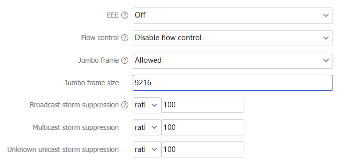
Table-4 Configuration items
Item
Description
Protocol exceptions
Select protocols in the
Received orOriginated area. Then, the received or sent packets of the selected protocols are directly permitted, bypassing security policies and bandwidth management policies.VRF
Select a VRF from the list. You can select an existing VRF or create a new one. For more information about creating a VRF, see the help on the
Network >Interface Configuration >VRF page.Speed
Specify the speed at which the interface transmits data. Options include:
autonegotiation —The device automatically detects and selects the optimal transmission speed.Maximum data transmission speed supported by the interface—The value varies by interface type. Typical Ethernet interface speeds include 10 Mbps, 100 Mbps, and 1 Gbps.
Duplex mode
Select a duplex mode from the list. Options include:
autonegotiation —The interface and the peer interface negotiate automatically to determine whether to operate in full duplex or half duplex mode.Full duplex —The interface can send packets and receive packets at the same time.Half duplex —The interface can only send or receive packets at the same time.
MAC address
Specify a MAC address in the format of H-H-H. You cannot edit the MAC address for a subinterface.
MTU
When the device receives a packet and finds that the packet length exceeds the MTU of the forwarding interface, the device will perform either of the following operations:
If the packet does not support fragmentation, the device drops the packet.
If the packet supports fragmentation, the device fragments the packets and forwards the fragments.
To alleviate the burden of fragmenting and reassembling packets on forwarding devices during transmission and to use network resources more efficiently, set the appropriate interface MTU value based on the actual network environment to minimize fragmentation occurrences.
TCP MSS
Set the maximum data payload size of a TCP data segment that can be sent through the interface.
Expected bandwidth
The expected bandwidth is available only for service modules, and does not affect the actual interface bandwidth.
Last hop holding
When an interface with this feature enabled receives the first packet of the forward traffic, the interface records the traffic characteristics and last hop in the high-speed cache. When the backward traffic reaches the device for forwarding, the device can guide packet forwarding based on the last hop information recorded. This feature ensures that the forward traffic from the peer end to the local end and the backward traffic from the local end to the peer end are transmitted on the same path. Therefore, traffic of the same session can be processed in the same way.
IP address
The following are methods available for assigning an IPv4 address to an interface:
Manual assignment.
DHCP.
PPPoE.
Support for DHCP and PPPoE depends on the device model.
Floating IP
The floating IP is an IP address attribute. It takes effect only on RBM networks, and does not affect the usage of the IP address in other scenarios. On an RBM network, the floating IP address configuration can simplify high availability (HA) configuration. Configure the floating IP address on the service interface of the primary HA device. Then, the address will be automatically synchronized to the secondary device. You do not need to configure the Virtual Router Redundancy Protocol (VRRP) virtual address on the service interface of the primary or secondary device. The floating IP address can be configured only on the primary device in primary/secondary mode and is not supported in dual-primary mode. The floating IP address cannot be configured, edited, or deleted on the secondary device.
Global unicast address
Use one of the following methods to configure an IPv6 global unicast address for an interface:
EUI-64 IPv6 address —The IPv6 address prefix of the interface is manually configured, and the interface ID is generated automatically by the interface.Manual configuration —The IPv6 global unicast address is manually configured.Stateless address autoconfiguration —The IPv6 global unicast address is generated automatically based on the address prefix information contained in the RA message.Stateful address autoconfiguration —The IPv6 global unicast address is obtained through DHCPv6.
You can configure multiple IPv6 global unicast addresses on an interface.
Link-local address
Configure IPv6 link-local addresses in one of the following methods:
Automatic generation —The device automatically generates a link-local address for an interface according to the link-local address prefix (FE80::/10) and the link-layer address of the interface.Manual assignment —Manually configure an IPv6 link-local address for an interface.
An interface can have only one link-local address. As a best practice, use the automatic generation method to avoid link-local address conflicts.
If both the automatic generation and manual assignment methods are used, the manual assignment takes precedence.
If you first use automatic generation and then manual assignment, the manually assigned link-local address overwrites the automatically generated one.
If you first use manual assignment and then automatic generation, both of the following occur:
The link-local address is still the manually assigned one.
The automatically generated link-local address does not take effect. If you delete the manually assigned address, the automatically generated link-local address takes effect.
EEE
With this feature enabled on an interface, if the interface remains up and no packets are sent or received for a continuous period, the interface will automatically enter low power mode.
When the interface needs to send and receive packets, it automatically returns to normal operating mode.
Flow control
With flow control enabled on an interface, if congestion occurs on the local device, the local device will send messages to notify the peer device to pause sending packets. Upon receiving the messages, the peer device will pause sending packets to the local device. This process applies both ways. Use this feature to avoid packet loss.
With Rx-mode flow control enabled on an interface, the local device will stop sending packets to the peer device when the local device receives flow control packets from the peer. If congestion occurs on the local device, the local device cannot send flow control packets to the peer device.
Jumbo frame
A jumbo frame refers to a frame longer than the standard Ethernet frame length. When a packet exceeds the allowed jumbo frame size, it will be dropped.
Jumbo frame size
Specify the jumbo frame size, which is typically 9216 bytes.
Broadcast storm suppression
With this feature enabled on an interface, when the broadcast traffic on the interface exceeds the suppression threshold, the system will drop the packets exceeding the threshold. This operation reduces the traffic to the specified range and ensures the normal operation of network services. Setting the ratio to 100 indicates no suppression.
ratio —Specify the proportion of the maximum permitted traffic to the interface bandwidth. Setting the value to 100 indicates no suppression.pps —Specify the maximum number of packets that can be forwarded on an interface per second. The value is in the range of 0 to 1.4881 × interface bandwidth.kbps —Specify the maximum number of kilobits that can be forwarded on an interface per second. The value is in the range of 0 to the interface bandwidth.
Multicast storm suppression
With this feature enabled on an interface, when the multicast traffic on the interface exceeds the suppression threshold, the system will drop the packets exceeding the threshold. This operation reduces the traffic to the specified range and ensures the normal operation of network services. Setting the ratio to 100 indicates no suppression.
ratio —Specify the proportion of the maximum permitted traffic to the interface bandwidth. Setting the value to 100 indicates no suppression.pps —Specify the maximum number of packets that can be forwarded on an interface per second. The value is in the range of 0 to 1.4881 × interface bandwidth.kbps —Specify the maximum number of kilobits that can be forwarded on an interface per second. The value is in the range of 0 to the interface bandwidth.
Unknown unicast storm suppression
With this feature enabled on an interface, when the unknown unicast traffic on the interface exceeds the suppression threshold, the system will drop the packets exceeding the threshold. This operation reduces the traffic to the specified range and ensures the normal operation of network services.
ratio —Specify the proportion of the maximum permitted traffic to the interface bandwidth. Setting the value to 100 indicates no suppression.pps —Specify the maximum number of packets that can be forwarded on an interface per second. The value is in the range of 0 to 1.4881 × interface bandwidth.kbps —Specify the maximum number of kilobits that can be forwarded on an interface per second. The value is in the range of 0 to the interface bandwidth.
Click
OK .
Configure Layer 2 interfaces
A Layer 2 Ethernet interface is a physical interface that operates at the data link layer and it can forward received packets at Layer 2.
To configure a Layer 2 interface:
On the
Interfaces page, select the interface you want to edit, and then clickEdit for that interface to access theModify Interface Settings page.Figure-8 Modifying the settings of a Layer 2 interface
From the
Link mode list, selectLayer 2 mode . Then, configure the following settings for the interface:Figure-9 Basic configuration
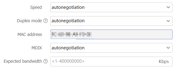
Figure-10 VLAN configuration
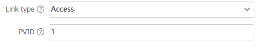
Figure-11 Physical interface configuration
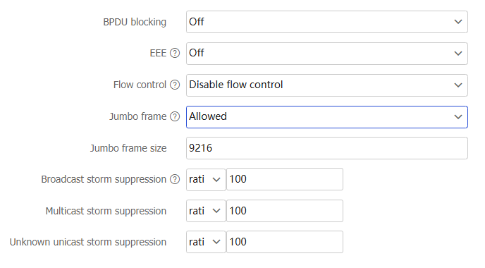
Table-5 Configuration items
Parameter
Description
Speed
Specify the speed at which the interface transmits data. Options include:
autonegotiation —The device automatically detects and selects the optimal transmission speed.Maximum data transmission speed supported by the interface—The value varies by interface type. Typical Ethernet interface speeds include 10 Mbps, 100 Mbps, and 1 Gbps.
Duplex mode
Select a duplex mode from the list. Options include:
autonegotiation —The interface and the peer interface negotiate automatically to determine whether to operate in full duplex or half duplex mode.Full duplex —The interface can send packets and receive packets at the same time.Half duplex —The interface can only send or receive packets at the same time.
MAC address
Specify a MAC address in the format of H-H-H. You cannot edit the MAC address for a subinterface.
MDIX
Select an MDIX mode from the list. Options include:
autonegotiation —Configure the interface to automatically adapt to straight-through or crossover cables.s traight-through —Configure the interface to use straight-through cables to connect devices of different types.c rossover —Configure the interface to use crossover cables to connect devices of the same type.
Expected bandwidth
The expected bandwidth is available only for service modules, and does not affect the actual interface bandwidth.
Link type
Depending on the VLAN tag handling mode, the link type of a port can be one of the following three:
Access —An access port can forward packets only from one VLAN and send these packets untagged. An access port is typically used in the following conditions:Connecting to a terminal device that does not support VLAN packets.
In scenarios that do not distinguish VLANs.
Trunk —A trunk port can forward packets from multiple VLANs. Except packets from the port VLAN ID (PVID), packets sent out of a trunk port are VLAN-tagged. Ports connecting network devices are typically configured as trunk ports.Hybrid —A hybrid port can forward packets from multiple VLANs. The tagging status of the packets forwarded by a hybrid port depends on the port configuration. Ports connecting network devices are typically configured as trunk ports.
PVID
Port VLAN ID (PVID) of an interface. When a port receives an untagged packet, the port transmits the packet in the PVID. When an access or trunk port sends packets from the PVID, the port removes the VLAN tag before sending the packets. An access port can join only one VLAN. The VLAN to which the access port belongs is the PVID of the port. A trunk or hybrid port supports multiple VLANs and the PVID configuration.
BPDU blocking
This feature prevents the propagation of unauthorized BPDUs within the spanning tree protocol.
EEE
With this feature enabled on an interface, if the interface remains up and no packets are sent or received for a continuous period, the interface will automatically enter low power mode.
When the interface needs to send and receive packets, it automatically returns to normal operating mode.
Flow control
With flow control enabled on an interface, if congestion occurs on the local device, the interface will send messages to notify the peer device to temporarily stop sending packets. Upon receiving the messages, the peer device will temporarily stop sending packets to the local device. Use this feature to avoid packet loss.
With Rx-mode flow control enabled on an interface, the local device will stop sending packets to the peer device when the local device receives flow control packets from the peer. If congestion occurs on the local device, the local device cannot send flow control packets to the peer device.
Jumbo frame
A jumbo frame refers to a frame longer than the standard Ethernet frame length. When a packet exceeds the allowed jumbo frame size, it will be dropped.
Jumbo frame size
Specify the jumbo frame size, which is typically 9216 bytes.
Broadcast storm suppression
With this feature enabled on an interface, when the broadcast traffic on the interface exceeds the suppression threshold, the system will drop the packets exceeding the threshold. This operation reduces the traffic to the specified range and ensures the normal operation of network services. Setting the ratio to 100 indicates no suppression.
ratio —Specify the proportion of the maximum permitted traffic to the interface bandwidth. Setting the value to 100 indicates no suppression.pps —Specify the maximum number of packets that can be forwarded on an interface per second. The value is in the range of 0 to 1.4881 × interface bandwidth.kbps —Specify the maximum number of kilobits that can be forwarded on an interface per second. The value is in the range of 0 to the interface bandwidth.
Multicast storm suppression
With this feature enabled on an interface, when the multicast traffic on the interface exceeds the suppression threshold, the system will drop the packets exceeding the threshold. This operation reduces the traffic to the specified range and ensures the normal operation of network services. Setting the ratio to 100 indicates no suppression.
ratio —Specify the proportion of the maximum permitted traffic to the interface bandwidth. Setting the value to 100 indicates no suppression.pps —Specify the maximum number of packets that can be forwarded on an interface per second. The value is in the range of 0 to 1.4881 × interface bandwidth.kbps —Specify the maximum number of kilobits that can be forwarded on an interface per second. The value is in the range of 0 to the interface bandwidth.
Unknown unicast storm suppression
With this feature enabled on an interface, when the unknown unicast traffic on the interface exceeds the suppression threshold, the system will drop the packets exceeding the threshold. This operation reduces the traffic to the specified range and ensures the normal operation of network services.
ratio —Specify the proportion of the maximum permitted traffic to the interface bandwidth. Setting the value to 100 indicates no suppression.pps —Specify the maximum number of packets that can be forwarded on an interface per second. The value is in the range of 0 to 1.4881 × interface bandwidth.kbps —Specify the maximum number of kilobits that can be forwarded on an interface per second. The value is in the range of 0 to the interface bandwidth.
Click
OK .
Create virtual interfaces
Virtual interfaces include various types. On the device, you can create virtual interfaces, such as aggregate interfaces, VLAN interfaces, and loopback interfaces. Create different types of virtual interfaces to meet various service requirements.
To create a virtual interface:
On the
Interfaces page, clickCreate interface .Figure-12 Creating an interface

Select an interface type. Then, configure the following settings:
Table-6 Interface configuration items
Parameter
Description
Type
Interface type. Options include:
Physical subinterface.
Layer 3 aggregate subinterface.
Reth subinterface.
Reth interface.
Layer 2 aggregate interface.
Layer 3 aggregate interface.
VLAN interface.
SSLVPN AC interface.
LoopBack interface.
Main interface
Physical interface based on which you can create a logical interface to handle the specific type of traffic.
Only physical subinterfaces, Layer 3 aggregate subinterfaces, and Reth subinterfaces support this parameter.
Number
Identifier of an interface.
This parameter is supported only when the type is physical subinterface, Layer 3 aggregate subinterface, Reth subinterface, Reth interface, or loopback interface.
Aggregation group ID
Identifier of a Layer 2 or Layer 3 aggregation group.
Interface number
Identifier of an SSLVPN AC interface.
VLAN
Select the VLAN for which you want to create a VLAN interface.
Click
OK .
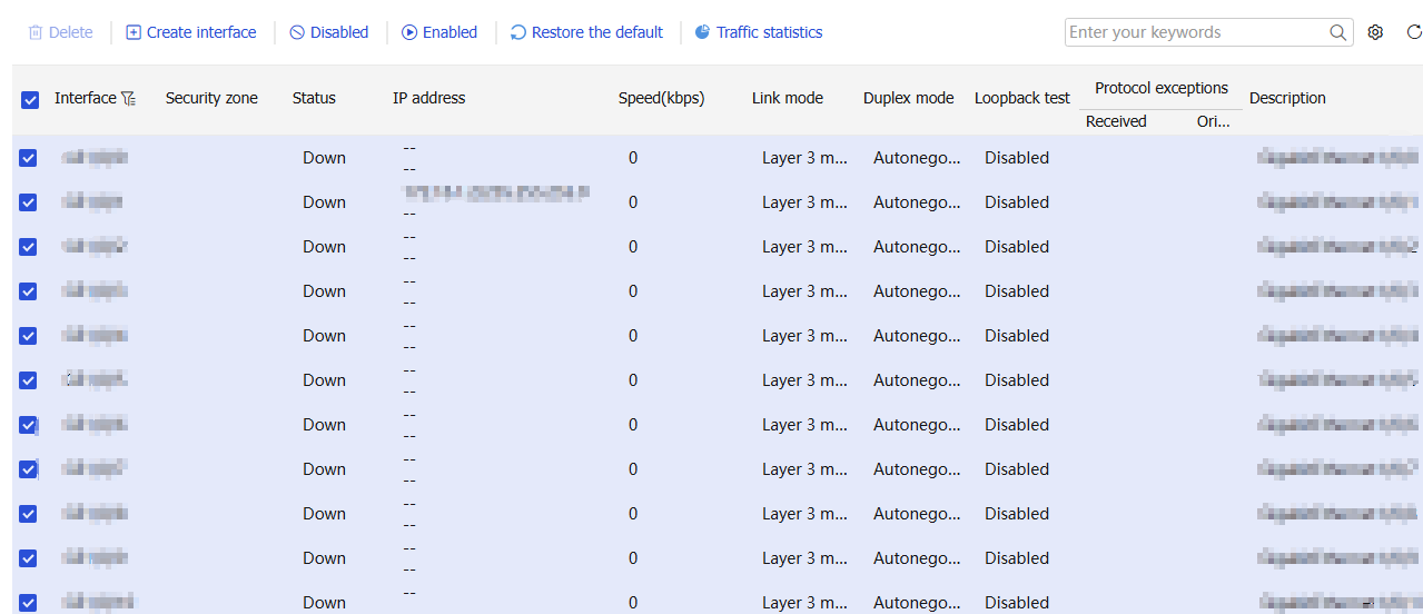
Manage interfaces
On the
Figure-13 Managing interfaces
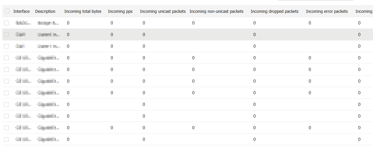
View traffic statistics
On the
Figure-14 Traffic statistics