GRE
This help contains the following topics:
Introduction
Generic Routing Encapsulation (GRE) is a tunneling protocol that can encapsulate a protocol (such as IPv4) into a virtual point-to-point tunnel over a network (such as an IPv6 network). Packets are encapsulated at one tunnel end and de-encapsulated at the other tunnel end. The network layer protocol of the packets before encapsulation and after encapsulation can be the same or different.
GRE encapsulation format
A GRE-tunneled packet includes the following parts:
Payload packet —Original packet. The protocol type of the payload packet is called the passenger protocol. The passenger protocol can be any network layer protocol.GRE header —Header that is added to the payload packet to change the payload packet to a GRE packet. A GRE header includes the number of encapsulations, version, passenger protocol type, checksum, and key. GRE is called the encapsulation protocol.Delivery header —Header that is added to the GRE packet to deliver it to the tunnel end. The transport protocol (or delivery protocol) is the network layer protocol that transfers GRE packets.The device supports GRE tunnels with IPv4 and IPv6 as the transport protocols. When the transport protocol is IPv4, the GRE tunnel mode is GRE over IPv4 (GRE/IPv4). When the transport protocol is IPv6, the GRE tunnel mode is GRE over IPv6 (GRE/IPv6).
GRE tunnel operating principle
An IPv4 or IPv6 protocol packet traverses a transport network through a GRE tunnel as follows:
After the source device receives an IPv4 or IPv6 protocol packet from a customer-side interface, it processes the packet as follows:
Looks up the routing table to identify the outgoing interface for the packet.
Submits the packet to the outgoing interface—a GRE tunnel interface.
Upon receiving the packet, the tunnel interface encapsulates the packet with GRE and then with the delivery header. In the delivery header, the source address is the tunnel's source address and the destination address is the tunnel's destination address.
The source device looks up the routing table according to the destination address in the delivery header. Then, the device forwards the encapsulated packet out of the physical interface of the GRE tunnel.
When the packet arrives at the GRE tunnel destination, the destination device checks the destination address. Because the destination is the device itself and the protocol number in the IP header is 47 (the protocol number for GRE), the device submits the packet to GRE for de-encapsulation.
GRE first removes the delivery header, and then checks the GRE key, checksum, and packet sequence number. After GRE finishes the checking, it removes the GRE header, and submits the payload to the passenger protocol for forwarding.
GRE keepalive mechanism
This mechanism enables a tunnel interface to send keepalive packets at the specified interval. If the device does not receive any response from the peer within the timeout time, it shuts down the local tunnel interface. The device brings the local tunnel interface up if it receives a keepalive acknowledgment packet from the peer. The timeout time is the result of multiplying the keepalive interval by the keepalive number.
The device always acknowledges the keepalive packets it receives whether or not GRE keepalive is enabled.
GRE security mechanisms
GRE supports the GRE key and GRE checksum security mechanisms.
GRE key
GRE keys ensure packet validity. The sender adds a GRE key into a packet. The receiver compares the GRE key with its own GRE key. If the two keys are the same, the receiver accepts the packet. If the two keys are different, the receiver drops the packet.
GRE checksum
GRE checksums ensure packet integrity. The sender calculates a checksum for the GRE header and payload and sends the packet containing the checksum to the tunnel peer. The receiver calculates a checksum for the received packet and compares it with that carried in the packet. If the checksums are the same, the receiver determines the packet intact and continues to process the packet. If the checksums are different, the receiver discards the packet.
vSystem support information
Support of non-default vSystems for this feature depends on the device model. This feature is available on the Web interface only if it is supported.
Restrictions and guidelines
When you configure a GRE tunnel, follow the restrictions and guidelines in this section.
Restrictions and guidelines: Address configuration
When the passenger protocol is IPv4, configure an IPv4 address for the tunnel interface at each tunnel end. When the passenger protocol is IPv6, configure an IPv6 address for the tunnel interface at each tunnel end.
You must configure the tunnel source address and destination address at both ends of a tunnel. The tunnel source or destination address at one end must be the tunnel destination or source address at the other end.
The IP address of a tunnel interface and the tunnel destination address configured on the tunnel interface must be in different subnets.
Restrictions and guidelines: Routing configuration
To ensure correct packet forwarding, identify whether the destination network of packets and the IP address of the local tunnel interface are on the same subnet. If they are not, configure a route reaching the destination network through the tunnel interface. You can configure the route by using one of the following methods:
Configure a static route, using the local tunnel interface as the outgoing interface of the route.
Enable a dynamic routing protocol on both the tunnel interface and the interface connecting the private network. This allows the dynamic routing protocol to establish a routing entry with the tunnel interface as the outgoing interface.
Restrictions and guidelines: Keepalive configuration
You do not need to enable keepalive on both ends of a GRE tunnel. Enable keepalive on one end of a GRE tunnel as needed.
Restrictions and guidelines: GRE security mechanism configuration
The two ends of a GRE tunnel must have the same key or both have no key.
You can enable or disable GRE checksum at each end of a tunnel. If GRE checksum is enabled at a tunnel end, the tunnel end sends packets carrying the checksum to the peer end. A tunnel end checks the GRE checksum of a received packet if the packet carries a GRE checksum, whether or not the tunnel end is enabled with GRE checksum.
Configure GRE
Prerequisites
Complete the following tasks before you configure this feature:
Assign IP addresses to interfaces on the
Network >Interface Configuration >Interfaces page.Configure routes on the
Network >Routing page. Make sure the routes are available.Create security zones on the
Network >Security Zones page.Add interfaces to security zones. You can add interfaces to a security zone on the
Security Zones page or select a security zone for an interface on theInterfaces page.Configure security policies to permit the target traffic on the
Policies >Security Policies page.
Configure a GRE over IPv4 tunnel
A GRE over IPv4 tunnel encapsulates and transmits packets of other protocols over an IPv4 network. It uses the GRE protocol to encapsulate packets of different protocols (such as IPv6 or other non-IP protocols) in IPv4 packets and transmits them over an IPv4 network, enabling inter-network transmission.
To configure a GRE over IPv4 tunnel:
Click the
Network tab.Select
VPN >GRE .Click
Create .Create a GRE tunnel interface. Select
IPv4 for theTransport protocol field.Figure-1 Creating a GRE tunnel interface
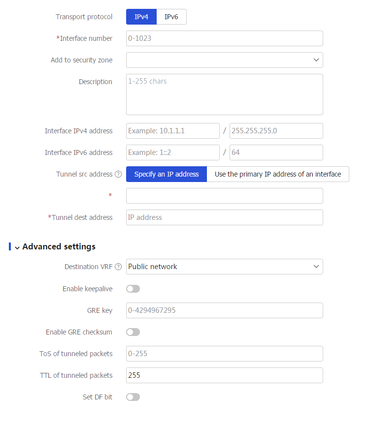
Table-1 Configuration items for GRE tunnel interface creation
Item
Description
Transport protocol
Select
IPv4 to specify the GRE over IPv4 tunnel mode.Interface number
Specify the interface number of the GRE tunnel interface.
Add to security zone
Specify the security zone to which the GRE tunnel interface belongs.
Description
Enter a description for the GRE tunnel interface.
Interface IPv4 address
Specify the IPv4 address of the tunnel interface.
Interface IPv6 address
Specify the IPv6 address of the tunnel interface.
Tunnel src address
Specify the source address for the tunnel. Options include
Specify an IP address andUse the primary IP address of an interface .If you select
Specify an IP address and configure the IP address, the tunnel interface uses the IP address as the source address of encapsulated packets.If you select
Use the primary IP address of an interface and configure the interface, the tunnel interface uses the primary IP address of the interface as the source address of encapsulated packets.
Tunnel dest address
Specify the destination address for the tunnel.
Destination VRF
Specify the tunnel destination VRF.
The device looks up the routing table of the specified VRF to forward tunneled packets on the tunnel interface.
Enable keepalive
Specify whether to enable keepalive.
With this feature enabled, the device sends keepalive packets at the specified interval to detect the state of the GRE tunnel.
Keepalive interval
Specify the keepalive interval at which keepalive packets are sent.
Max keepalive number
Specify the max keepalive number of keepalive packets.
If this number is reached and the device receives no response from the peer, the device detects that the GRE tunnel is disconnected.
GRE key
Specify the GRE key for checking the validity of packets.
Enable GRE checksum
Specify whether to enable GRE checksum for checking the integrity of packets.
ToS of tunneled packets
Set the ToS for tunneled packets.
With this feature configured, the packets forwarded by the same GRE tunnel carry the same ToS value.
TTL of tunneled packets
Set the TTL for tunneled packets.
If the number of hops between two devices exceeds the specified TTL value, they cannot communicate with each other.
Set DF bit
Specify whether to set DF bit for tunneled packets.
With this feature configured, the device does not allow fragmentation of tunneled packets and fragmentation delay can be avoided.
Click
OK .
Configure a GRE over IPv6 tunnel
A GRE over IPv6 tunnel encapsulates and transmits packets of other protocols over an IPv6 network. It uses the GRE protocol to encapsulate packets of different network layer protocols in IPv6 packets and transmits the packets over an IPv6 network.
To configure a GRE over IPv6 tunnel:
Click the
Network tab.Select
VPN >GRE .Click
Create .Create a GRE tunnel interface. Select
IPv6 for theTransport protocol field.Figure-2 Creating a GRE tunnel interface
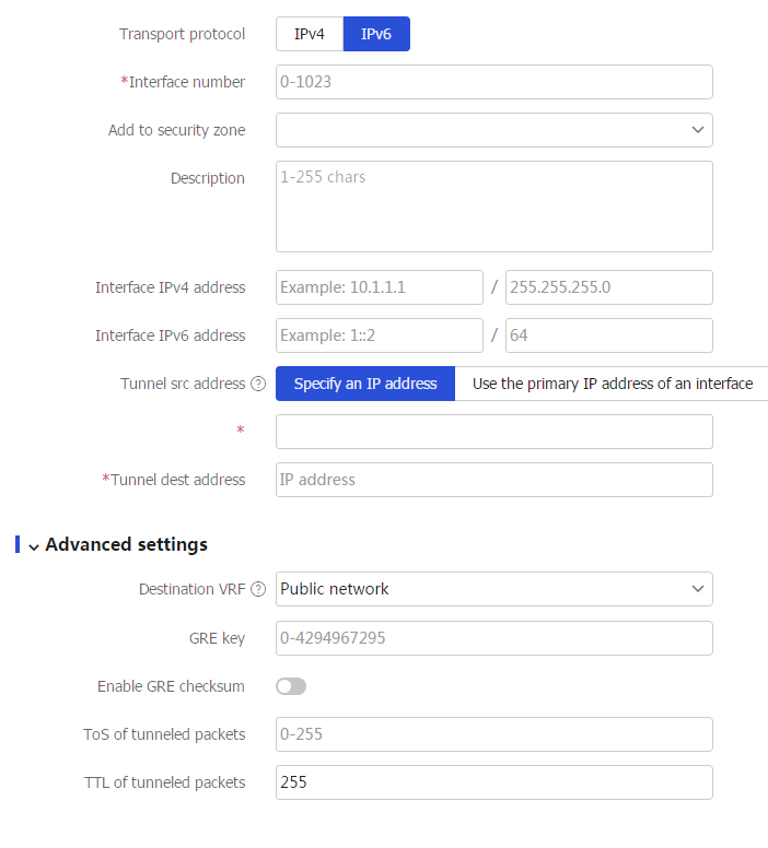
Table-2 Configuration items for GRE tunnel interface creation
Item
Description
Transport protocol
Select
IPv6 to specify the GRE over IPv6 tunnel mode.Interface number
Specify the interface number of the GRE tunnel interface.
Add to security zone
Specify the security zone to which the GRE tunnel interface belongs.
Description
Enter a description for the GRE tunnel interface.
Interface IPv4 address
Specify the IPv4 address of the tunnel interface.
Interface IPv6 address
Specify the IPv6 address of the tunnel interface.
Tunnel src address
Specify the source address for the tunnel. Options include
Specify an IP address andUse the primary IP address of an interface .If you select
Specify an IP address and configure the IP address, the tunnel interface uses the IP address as the source address of encapsulated packets.If you select
Use the primary IP address of an interface and configure the interface, the tunnel interface uses the primary IP address of the interface as the source address of encapsulated packets.
Tunnel dest address
Specify the destination address for the tunnel.
Destination VRF
Specify the tunnel destination VRF.
The device looks up the routing table of the specified VRF to forward tunneled packets on the tunnel interface.
GRE key
Specify the GRE key for checking the validity of packets.
Enable GRE checksum
Specify whether to enable GRE checksum for checking the integrity of packets.
ToS of tunneled packets
Set the ToS for tunneled packets.
With this feature configured, the packets forwarded by the same GRE tunnel carry the same ToS value.
TTL of tunneled packets
Set the TTL for tunneled packets.
If the number of hops between two devices exceeds the specified TTL value, they cannot communicate with each other.
Click
OK .