Contexts
This help contains the following topics:
Introduction
A physical firewall or an IRF fabric can be virtualized into multiple logical firewalls called contexts. Each context is assigned separate hardware and software resources, and operates independently of other contexts. From the user's perspective, a context is a standalone firewall.
Default context and non-default contexts
A device supporting contexts is considered to be a context. This context is called the default context. The default context always uses the name Admin and the ID 1. You cannot delete it or change its name or ID.
When you log in to the physical firewall, you are logged in to the default context. On the default context, you can perform the following tasks:
Manage the entire physical firewall.
Create and delete non-default contexts.
Assign non-default contexts resources, including CPU resources, disk space, memory space, interfaces, and VLANs.
You cannot create contexts on a non-default context.
A non-default context can use only resources assigned to it. Resources that are not assigned to non-default contexts belong to the default context.
Unless otherwise stated, the term "context" on webpages refers to a non-default context.
Security engine and security engine groups
The firewall is equipped with hardware security engines. A context can run and provide services only after you assign it to a security engine group.
To simplify management, the firewall manages security engines by using security engine groups.
By default, the firewall has a default security engine group, which is named Default and numbered 1. All security engines belong to the default security engine group.
A security engine can belong to only one security engine group.
A security engine group can have multiple security engines. The system automatically elects one security engine as the main security engine. Other security engines act as backup security engines. When the main security engine cannot operate correctly, the system automatically elects another security engine as the main security engine.
Assigning resources to a context
You can assign a context CPU resources, disk space, memory space, interfaces, and VLANs.
Assigning VLANs to a context
When you create a context, you can specify whether the context share VLAN resources with other contexts.
Shared mode—Share VLAN resources with other contexts. The VLANs can be created and managed only on the default context. Non-default contexts can use only VLANs assigned from the default context. A VLAN can be used by multiple contexts. After receiving a packet, the physical device forwards the packet to the context that matches the incoming interface and VLAN tag of the packet. This mode applies scenarios where multiple contexts share the same VLANs.
Exclusive mode—Do not share VLAN resources with other contexts. Administrators of the context must log in to the context and create VLANs for the context. This mode applies scenarios where contexts require their independent VLANs.
Assigning interfaces to a context
By default, all interfaces belong to the default context. A non-default context cannot use any interfaces. To enable a non-default context to communicate, you must assign it interfaces.
You can assign interfaces to contexts in exclusive or shared mode:
Exclusive mode—An interface assigned to a context in this mode belongs to the context exclusively. After logging in to the context, you can see the interface and use all commands supported on the interface.
Shared mode—When you assign an interface to multiple contexts in shared mode, the system creates a virtual interface for each context. The virtual interfaces use the same name as the physical interface but have different MAC addresses and IP addresses. They forward and receive packets through the physical interface. The shared mode improves interface usage.
You can see the physical interface and perform all commands supported on the interface from the default context. The administrator of a context can only see the context's virtual interface and use the shutdown, description, and network- and security-related commands.
Specifying a CPU weight for a context
When the CPU resources cannot meet the processing requirements from contexts, the system allocates CPU resources as follows:
Identifies the CPU weights of all contexts.
Calculates the percentage of each context's CPU weight among the CPU weights of all contexts.
Allocates CPU resources to contexts based on their CPU weight percentages.
For example, three contexts share the same CPU. You can assign a weight of 2 to the key context and a weight of 1 to each of the other two contexts. When the system is running out of CPU resources, the key context can use approximately two times of the CPU resources that each of the other two contexts can use.
Assigning disk and memory resources to a context
To prevent one context from occupying too many disk or memory resources, specify a disk space percentage and a memory space percentage for the context.
| Before you specify a disk or memory space percentage for a context, start the context and view the amount of disk or memory space that the context is using. Make sure the disk or memory space you assign to a context is sufficient for the context to start and operate correctly. |

Setting the maximum number of concurrent unicast sessions
A large number of sessions occupy too much memory. This degrades context performance and affects other contexts. When the maximum number is reached, no additional sessions can be established. To solve this issue, set the maximum number of concurrent unicast sessions for a context.
This feature does not affect local traffic, such as FTP traffic and Telnet traffic.
| A context has the same maximum number of concurrent unicast sessions on all security engines. If packets are processed on multiple security engines, the actual limit is greater than the setting. |

If the maximum number you set is smaller than the number of existing concurrent unicast sessions, this setting takes effect. The context does not delete extra existing concurrent unicast sessions and allows new unicast sessions to be created only when the number of concurrent unicast sessions drops below the maximum number.
Setting the upper limit of the session establishment rate
This feature limits the number of sessions that can be established per second for a context. If a context establishes sessions too frequently, other contexts will not be able to establish sessions because of inadequate CPU processing capacity. When the upper limit is reached for a context, no additional sessions can be established.
This feature does not affect local traffic, such as FTP traffic and Telnet traffic.
| A context has the same upper limit of the session establishment rate on all security engines. If packets are processed on multiple security engines, the actual limit is greater than the setting. |

Setting the maximum number of security policy rules
This feature limits the number of security policy rules that can be configured for a context. Security policy rules occupy memory space. Configuring too many security policy rules might affect operation of other features. When the upper limit is reached for a context, no additional security policy rules can be configured.
If the maximum number you set is smaller than the number of existing security policy rules, this setting takes effect. The context does not delete extra existing security policy rules and allows new security policy rules to be created only when the number of security policy rules drops below the maximum number.
Setting the maximum number of SSL VPN users
This feature limits the number of SSL VPN users that can log in to a context. When the maximum number is reached, the context will reject the login requests of new SSL VPN users.
If the maximum number you set is smaller than the number of SSL VPN users that already have logged in to a context, this setting takes effect. The context does not log out the currently logged-in users and allows new users to log in only when the number of the logged-in users drops below the maximum number.
Setting a throughput threshold
This feature limits the throughput for a context to prevent it from occupying too many shared resources on the device. This feature drops service packets preferentially to ensure forwarding of protocol packets.
| A context has the same throughput threshold on all security engines. If packets are processed on multiple security engines, the actual throughput is greater than the setting. |

The device supports the following types of logging for context throughputs:
Throughput limits drop logging—If a throughput limit is set for a context, the device drops packets for the context after the real-time throughput of the context reaches the throughput limit. In addition, the device periodically generates throughput limit drop logs for the context. When the throughput of the context drops below the throughput limit, the device generates recovery logs and stops dropping packets for the context.
Throughput alarm logging—If a throughput limit is set for a context, the device generates a throughput alarm log when the ratio of the context real-time throughput to the throughput limit exceeds the alarm threshold. When the ratio of the context real-time throughput to the throughput limit drops below the alarm threshold, the device generates a recovery log.
Collecting information
On the default context, you can collect log messages, diagnostic information, and configuration information about multiple or all contexts.
Rate limiting
Throughput limit alarm
To prevent excessive packets from a context from leading to the drop of packets from other contexts, you must limit the outbound throughput of the context.
You can enable throughput limit drop logging and throughput alarm logging to promptly monitor throughput changes.
Throughput limit drop logging—With this feature enabled, when the outbound throughput of a context reaches the outbound throughput limit, the device will drop packets exceeding the throughout limit for the context. In addition, the device will generate throughput limit drop logs for the context. When the outbound context throughput drops below the outbound throughput limit, the device generates recovery logs.
Throughput alarm logging—With this feature enabled and an alarm threshold set, the device generates a throughput alarm log when the ratio of the outbound context throughput to the outbound throughput limit exceeds the alarm threshold. When the ratio of the outbound context throughput to the outbound throughput limit drops below the alarm threshold, the device generates a recovery log.
The generated log messages will be sent to the information center. The information center configuration specifies the log message sending rule and destination.
This feature limits throughput based on the CPU and takes effect only when fast forwarding is not hardware-based.
Total rate limit and per-context rate limit
Rate limiting takes effect only on active contexts that share interfaces with other contexts.
Rate limiting controls the numbers of incoming broadcast packets and multicast packets in a second on contexts. This feature prevents a context from using too many resources and degrading the service processing capabilities of other contexts.
This feature uses the following limits:
Total broadcast rate limit—Limit on the total number of incoming broadcast packets in a second on the device.
Total multicast rate limit—Limit on the total number of incoming multicast packets in a second on the device.
Per-context broadcast rate limit—Limit on the number of incoming broadcast packets in a second on a context.
Per-context multicast rate limit—Limit on the number of incoming multicast packets in a second on a context.
When both a per-context limit and the corresponding total limit are reached, the device drops subsequent packets of the type that arrive at the context.
Setting a total limit to 0 disables the corresponding rate limiting feature.
If an effective per-context limit is smaller than 1000, the value is the default limit. A default limit is the corresponding total limit divided by the number of active contexts that share interfaces with other contexts.
If an effective per-context limit is equal to or greater than 1000, the value might be the default limit or the configured limit.
With the context rate limit log feature enabled, context rate limit log messages are generated when the broadcast or multicast packets received by a context are discarded because the rate reaches the upper limit. Context rate limit log messages can only be output as system log messages.
vSystem support information
Support of non-default vSystems for this feature depends on the device model. This feature is available on the Web interface only if it is supported.
Restrictions and guidelines
Restrictions and guidelines: Security engine groups
A context can be assigned to only one security engine group. A security engine group can be associated with multiple contexts.
A security engine can join only one security engine group. A security engine group can have multiple security engines.
If you remove the last security engine from a non-default security engine group, the system automatically deletes the non-default security engine group.
If you move a security engine from one security engine group to another security engine group, the system automatically reboots the security engine and the service on the engine stops. Configure security engine groups before configuring features for the security engine groups.
For the system to operate correctly, the default security engine group must have a minimum of one security engine that is operating correctly.
Restrictions and guidelines: VLAN assignment
VLANs to be shared must already exist. Before assigning VLANs to contexts, you must create the VLANs on the default context.
The following VLANs cannot be shared among contexts:
VLAN 1.
Default VLANs of ports.
VLANs for which VLAN interfaces have been created.
Restrictions and guidelines: Interface assignment
Physical interfaces can be assigned to a context in shared or exclusive mode. Logical interfaces such as subinterfaces and aggregate interfaces can be assigned to a context only in shared mode.
After assigning a subinterface to a context, you cannot assign its primary interface to any contexts. After assigning a primary interface to a context, you cannot assign its subinterfaces to any contexts.
After assigning an interface to one context in shared mode, you cannot assign the interface to other contexts in exclusive mode before reclaiming the interface from the context.
When the device operates in IRF mode, do not assign IRF physical interfaces to a non-default context.
Member interfaces of an aggregate interface cannot be assigned to a context.
A member interface of a Reth interface cannot be assigned to a context. If a member interface of a Reth interface is a subinterface, the corresponding primary interface cannot be assigned to a context either.
Restrictions and guidelines: Information collection
On the default context, you cannot collect log messages for a non-default context that is never started.
On the default context, you cannot collect configuration information for a non-default context that is not started.
Restrictions and guidelines: Stopping a context
Stop a context with caution. Stopping a context stops all services on the context and logs out all users on the context.
Manage contexts
After creating a context, you can view the resources allocation and usage of that context from the resources allocation page and resources usage page.
Create a non-default context
Creating a context is equivalent to constructing a new device.
To create a context:
Click the System tab.
In the navigation pane, select Virtualization advanced settings > Contexts > Contexts.
Click Create and configure the settings for creating a context as described in the following table.
Figure-1 Creating a context
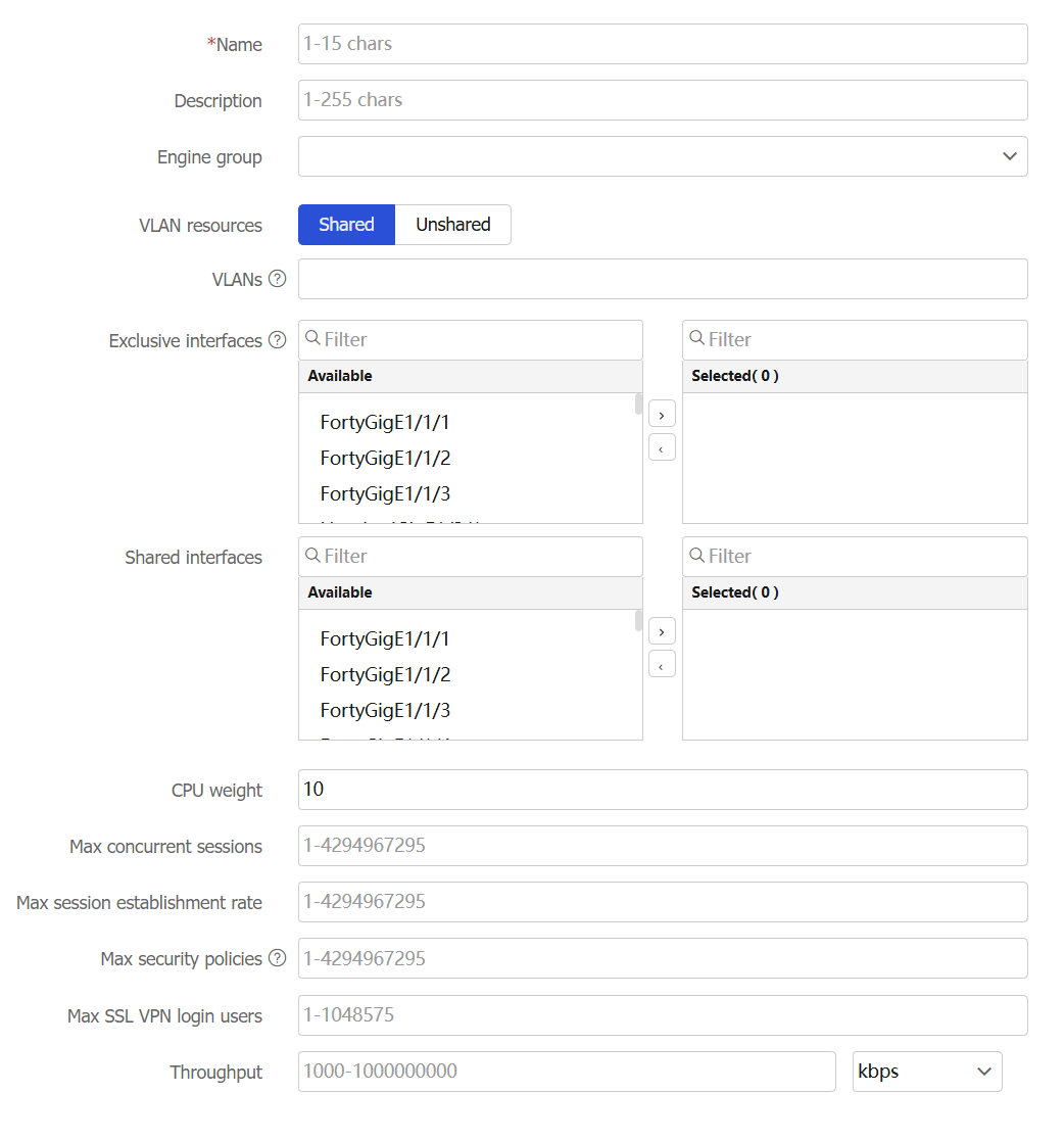
Configure a context.
Table-1 Configuration items for creating a context
Item
Description
Name
Enter a name for the context.
Description
Enter a description for the context.
Security engine group
Specify a security engine group for the context. For services to run on a context, you must specify a security engine group for that context. If you specify a security engine group for a context, you specify all security engines in the group.
The device has a default security engine group named Default, with an ID of 1.
VLAN resources
Specify whether the context shares VLAN resources with other contexts.
Shared—Share VLAN resources with other contexts.
Exclusive—Do not share VLAN resources with other contexts.
VLANs
Specify a list of VLANs to assign to the context. The VLANs in the list can be contiguous or not contiguous, for example, 3,5,10-100.
Exclusive Interfaces
Select interfaces to assign to the context exclusively. These interfaces belong to the context exclusively. After logging in to the context, you can see the interfaces and use all commands supported on the interfaces.
Shared interfaces
Select interfaces to assign to the context nonexclusively. These interfaces can be assigned to multiple contexts. These contexts share the interface and the system creates a virtual interface for each context. The virtual interfaces use the same name as the physical interface but have different MAC addresses and IP addresses. They forward and receive packets through the physical interface. The shared mode improves interface usage.
For each shared interface, you can see the physical interface and perform all commands supported on the interface from the default context. On a non-default context, you can only see the context's virtual interface and use the shutdown, description, and network- and security-related commands.
CPU weight
Set a CPU weight for the context. The greater the CPU weight, the more CPU resources assigned to the context.
Max concurrent sessions
Set the maximum number of concurrent unicast sessions for the context. When the maximum number is reached, no additional sessions can be established for the context.
Max session establishment rate
Set the upper limit of the session establishment rate for the context. When the upper limit is reached, no additional sessions can be established for the context.
Max security policies
Set the maximum number of security policy rules for the context. When the maximum number is reached, no additional security policy rules can be configured for the context.
Max SSL VPN login users
Set the maximum number of SSL VPN users that can log in to the context. When the maximum number is reached, the context will reject the login requests of new SSL VPN users.
Throughput
Set the throughput threshold for the context. When the threshold is reached, the device drops packets for the context.
Click OK.
The system returns to the Contexts page. Information about the context is displayed in the context list.
Add a context to a security engine group
For a context to run services after you create the context, you must add it to a security engine group to provide an actual operating environment.
To add a context to a security engine group:
Click the System tab.
In the navigation pane, select Virtualization advanced settings > Contexts > Security Engine Group.
Select a security engine.
Click Add to security engine group.
Figure-2 Security engines
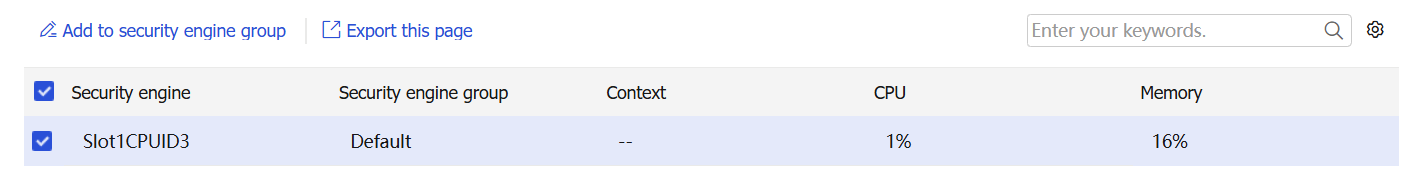
Figure-3 Adding a context to a security engine group
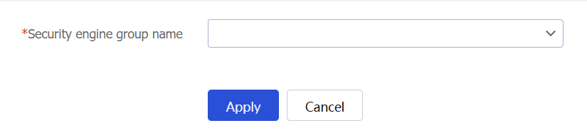
Select a security engine group.
Click Apply.
In the dialog box that opens, click OK. The device will restart the security engine.
Allocate resources to a context
View interface resources allocated to a context
On the Interface Allocation page, you can view interface allocation information and create logical interfaces.
To allocate interface resources to a context:
Click the System tab.
In the navigation pane, select Virtualization advanced settings > Contexts > Interface Allocation.
Click Create.
Figure-4 Interface allocation
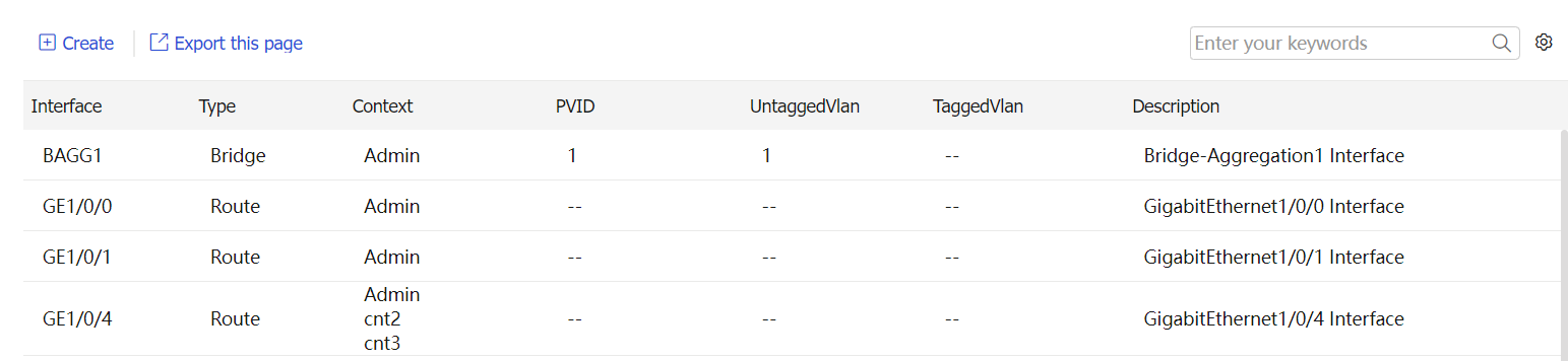
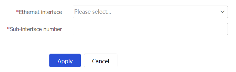
Figure-5 Creating an Ethernet subinterface
Configure an Ethernet subinterface as described in the following table.
Table-2 Ethernet subinterface creation configuration items
Item
Description
Ethernet interface
Select the Ethernet interface on which you are to create a subinterface
Sub-interface number
Specify the subinterface number.
Click Apply.
Allocate hardware resources to a context
Click the System tab.
In the navigation pane, select Virtualization advanced settings > Contexts > Resource Allocation.
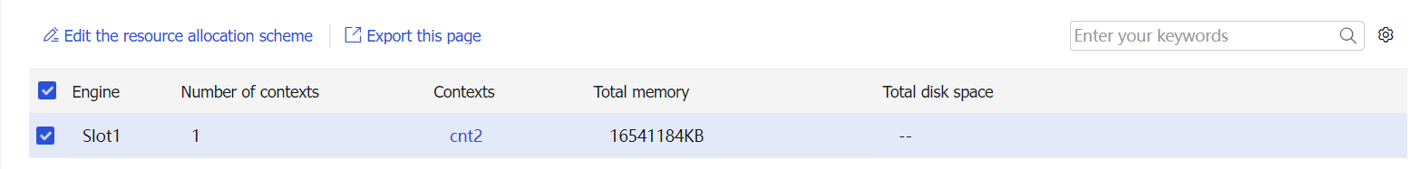
Select a context, and then click Edit the resource allocation scheme.
Figure-6 Resource allocation schemes
Allocate hardware resources for the context.
Figure-7 Editing a resource allocation scheme
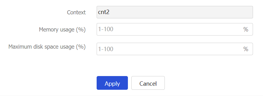
Click Apply.
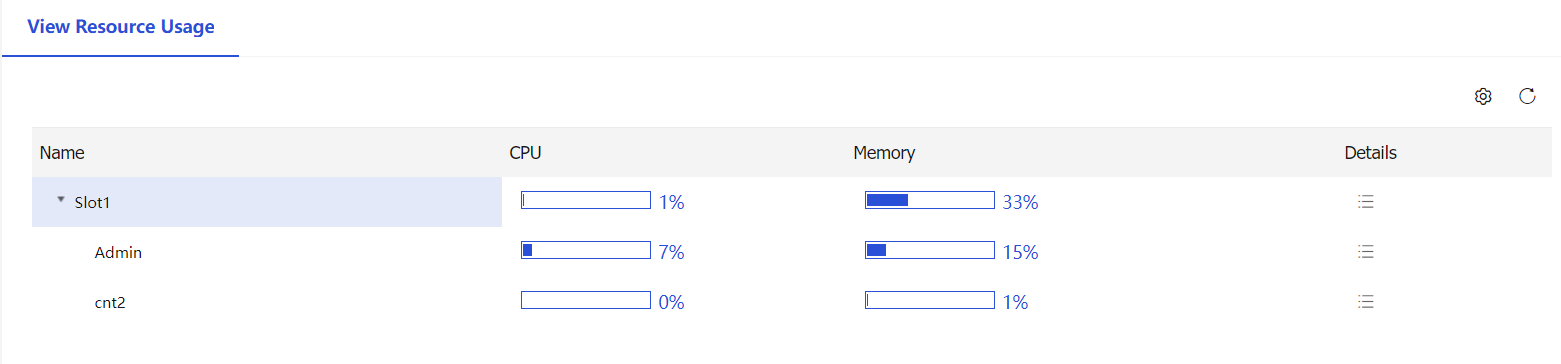
You can view the hardware resource usage on the System > Virtualization advanced settings > Contexts > Resource Usage page.
Figure-8 Viewing the resource usage
Configure rate limits for a context
To prevent excessive packets from a context from leading to the drop of packets from other contexts, you must limit the outbound throughput of the context.
To limit the outbound throughput of a context:
Click the System tab.
In the navigation pane, select Virtualization advanced settings > Contexts > Rate Limit.
Configure throughput limits alarms as described in the following table.
Figure-9 Configuring throughput limits alarms
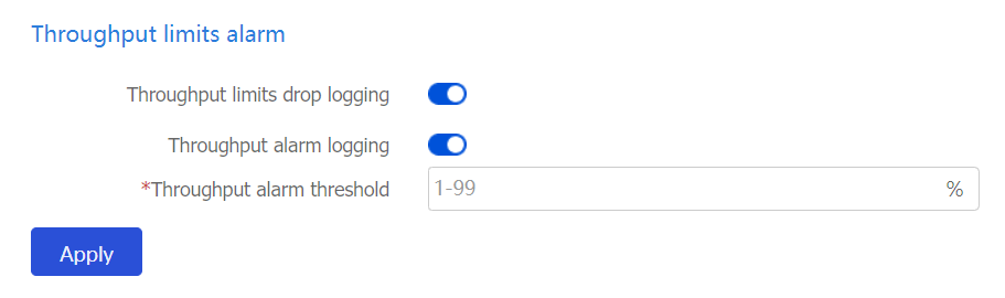
Table-3 Configuration items for throughput limits
Item
Description
Throughput limits drop logging
Select whether to enable throughput limit drop logging.
After you enable this feature and set a throughput limit for a context, the device drops packets for the context after the real-time throughput of the context reaches the throughput limit. In addition, the device periodically generates throughput limit drop logs for the context. When the throughput of the context drops below the throughput limit, the device generates recovery logs and stops dropping packets for the context.
Throughput alarm logging
Select whether to enable throughput alarm logging.
After you enable this feature and set a throughput limit for a context, the device generates a throughput alarm log when the ratio of the context real-time throughput to the throughput limit exceeds the alarm threshold. When the ratio of the context real-time throughput to the throughput limit drops below the alarm threshold, the device generates a recovery log.
Throughput alarm threshold
Set the throughput alarm threshold.
Click Apply.
Configure the total rate limits as described in the following table.
Figure-10 Configuring the total rate limits
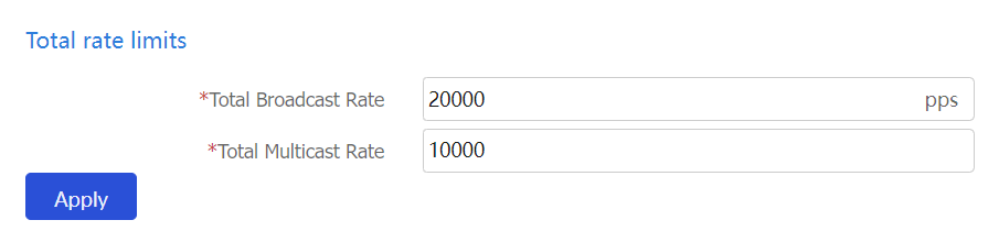
Table-4 Configuration items for total broadcast and multicast rates
Item
Description
Total Broadcast Rate
Limit on the total number of incoming broadcast packets in a second on the device.
When both the total broadcast rate limit and the broadcast rate limit configured for a context are reached, the device drops subsequent broadcast packets that arrive at the context.
Total Multicast Rate
Limit on the total number of incoming multicast packets in a second on the device.
When both the total multicast rate limit and the multicast rate limit configured for a context are reached, the device drops subsequent multicast packets that arrive at the context.
Click Apply.
Click the icon in the Edit column for a context. Configure the rate limits for that context as described in the following table.
Figure-11 Rate limits for contexts
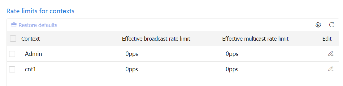
Figure-12 Configuring the rate limits for a single context
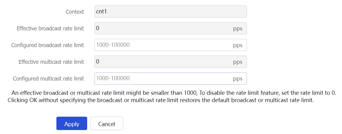
Table-5 Configuration items for rate limits for a single context
Item
Description
Context
Name of the context for which rates will be limited.
Effective broadcast rate limit
Rate limit for the broadcast packets in the inbound direction of the default context. This field is unavailable for non default contexts.
Broadcast rate limit for a context
Limit on the number of incoming broadcast packets in a second on a context.
When both the total broadcast rate limit and the broadcast rate limit configured for a context are reached, the device drops subsequent broadcast packets that arrive at the context.
Effective multicast rate limit
Rate limit for the multicast packets in the inbound direction of the default context. This field is unavailable for non default contexts.
Multicast rate limit for a context
Limit on the number of incoming multicast packets in a second on a context.
When both the total multicast rate limit and the multicast rate limit configured for a context are reached, the device drops subsequent multicast packets that arrive at the context.
Click Apply.
Switch contexts
Click the dropdown icon to the right of the account in the upper right corner of the page.
On the menu that opens, click Switch context.
Figure-13 Switching a context
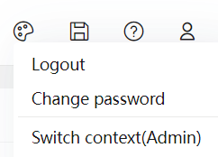
In the dialog box that opens, specify a context and click OK.
Figure-14 Switching a context