Security zones
This help contains the following topics:
Introduction
Security zone
A security zone is a collection of interfaces that have the same security requirements. You can configure security zones to implement security zone-based security management.
Security zone members
A security zone can include the following types of members:
Layer 2 interface-VLAN combination
Layer 3 interface:
Layer 3 Ethernet interface
Layer 3 logical interface, such as a Layer 3 subinterface
Security zone-based packet processing rules
The following table describes how the device handles packets when security zone-based security management is configured:
Packets | Action |
Packets between an interface that is in a security zone and an interface that is not in any security zone | Discard. |
Packets between two interfaces that are in the same security zone | Forward by default. |
Packets between two interfaces that belong to different security zones | Forward or discard, depending on the matching security control policy. If no policy is applied or the policy does not exist or does not take effect, the packets are discarded. |
Packets between two interfaces that are not in any security zone | Forward. |
Packets originated from or destined for the device itself | Forward or discard, depending on the matching object policy. By default, these packets are discarded. |
Whitelist
This feature exempts packets sourced from the subnets specified in the whitelisted address object group from attack detection. Packets from the whitelisted address are directly forwarded whether they are attack packets or not.
The whitelist can contain only one address object group. The address object group can only be manually added to or deleted from the whitelist.
Restrictions and guidelines
A Layer 3 interface can be added to only one security zone.
A Layer 2 interface-VLAN combination can be added to only one security zone.
If a packet does not match any zone pair between specific security zones, the device searches for the any-to-any zone pair.
If the zone pair exists, the device processes the packet by using the security policies applied to the zone pair.
If the zone pair does not exist, the device discards the packet.
By default, the device forwards packets between the
Management andLocal zones.For packets between the
Management andLocal security zones, the device uses only security control policies applied to the zone pairs of the two security zones.
Configure security zones
Configure attack defense as shown in
Figure-1 Security zone configuration procedure
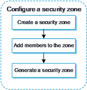
Configure a security zone
A security zone is a logical concept. The administrator classifies interfaces with the same security requirements and assigns them to different security zones to enable unified management of inter-zone policies. Inter-zone policies can be used to inspect traffic flows, and actions are executed on packets based on the inspection results.
To configure a security zone:
Click the
Network tab.In the navigation pane, select
Security Zone s .Click
Create .Configure security zone parameters as needed.
Figure-2 Creating a security zone
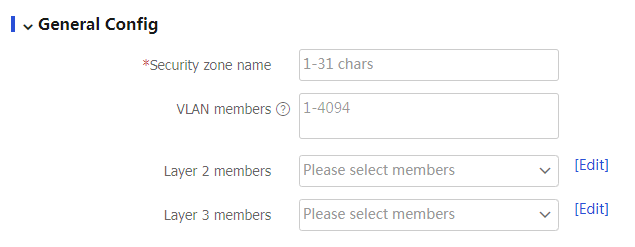
Table-1 Security zone configuration items
Item
Description
Security zone name
Configure the security zone name.
VLAN members
Add VLANs to the security zone as members.
Layer 2 members
Add Layer 2 interfaces to the security zone as members.
Layer 3 members
Add Layer 3 interfaces to the security zone as members.
Click
OK . The newly created security zone is displayed on theSecurity Zones page.
(Optional) Configure the whitelist
The whitelist feature exempts packets sourced from the IP addresses specified in the whitelisted address object group from attack detection.
Only address object groups can be manually added to or deleted from the whitelist. To configure an address object group, access the
To configure the whitelist:
Click the
Network tab.In the navigation pane, select
Security Zones >Whitelist .Click
Create .Add an address object group to the whitelist.
Figure-3 Adding an address object group to the whitelist
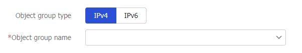
Table-2 Whitelist configuration items
Item
Description
Object group type
Select an IP version, IPv4 or IPv6.
Object group name
You can select an existing address object group or create a new one. The newly created address object group will be displayed on the
Objects >Object Groups page.Click
OK .
(Optional) Configure client verification
IP addresses protected by client verification can be manually added or automatically learned. The device can automatically add victims' IP addresses to the protected IP list when client verification collaborates with flood attack detection. The device directly forwards packets from trusted IP addresses. Make sure client verification is specified as the flood attack prevention action.
To configure client verification:
Click the
Network tab.In the navigation pane, select
Security Zones >Client Verification .Click
Create .Configure client verification.
Figure-4 Configuring client verification
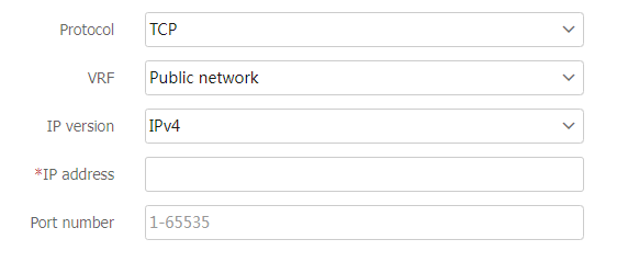
Table-3 Client verification configuration items
Item
Description
Protocol
Protocol type for client verification:
TCP —Specifies TCP client verification.DNS —Specifies DNS client verification.DNS reply —Specifies DNS reply source verification.HTTP —Specifies HTTP client verification.HTTPS —Specifies HTTPS client verification.SIP —Specifies SIP client verification.
VRF
VRF to which the protected IP address belongs. You can select an existing VRF or create a new one. The newly created VRF will be displayed on the
Network >VRF page.IP version
Select an IP version, IPv4 or IPv6.
IP address
Protected IP address. All connection requests destined for this address are verified by the client verification feature. The attacker sends TCP connection requests, DNS queries, DNS replies, HTTP GET requests, HTTP POST requests, HTTPS request, or SIP UDP INVITE requests to the protected IP.
Port number
Number of a protected port. By default, DNS client verification protects port 53, HTTP client verification protects port 80, HTTPS client verification protects port 443, SIP client verification protects port 5060, and TCP client verification protects all ports.
Click
OK . TheClient Verification page displays protected IP addresses manually added and automatically learned.