Outbound link load balancing
This help contains the following topics:
Introduction
How it works
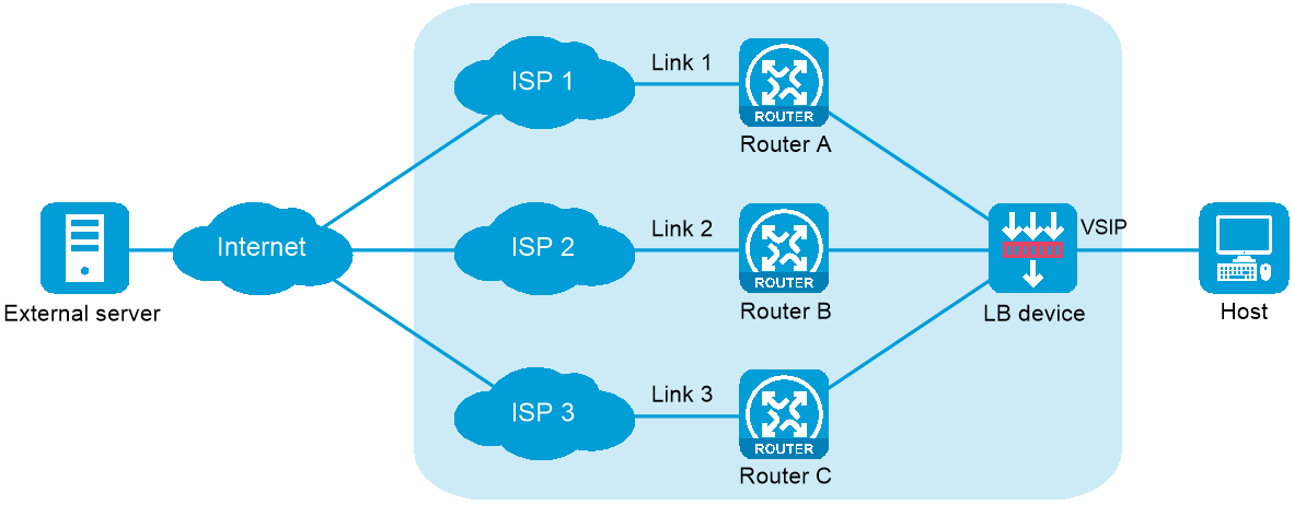
Outbound link load balancing load balances traffic among the links from the internal network to the external network.
As shown in Figure-1, outbound link load balancing contains the following elements:
LB device —Distributes outbound traffic among multiple links.Link —Physical links provided by ISPs.VSIP —Virtual service IP address of the cluster, which identifies the destination network for packets from the internal network.Server IP —IP address of a server, used by the LB device to distribute requests.
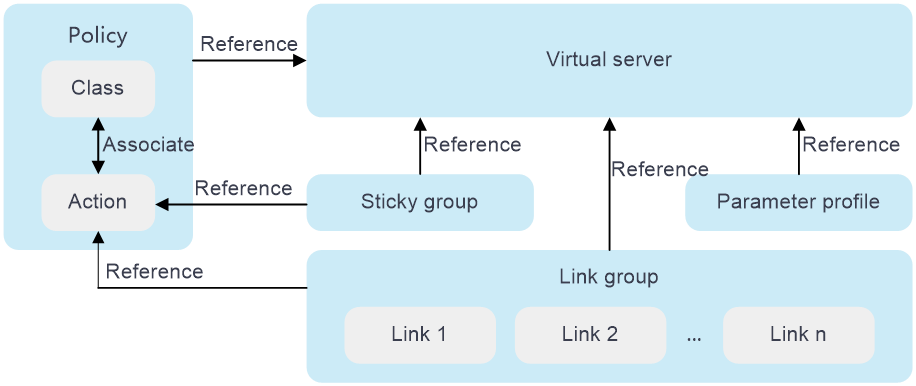
Relationship among configuration items
Figure-2 Relationship between the main configuration items
vSystem support information
Support of non-default vSystems for this feature depends on the device model. This feature is available on the Web interface only if it is supported.
Configure outbound link load balancing
Analysis
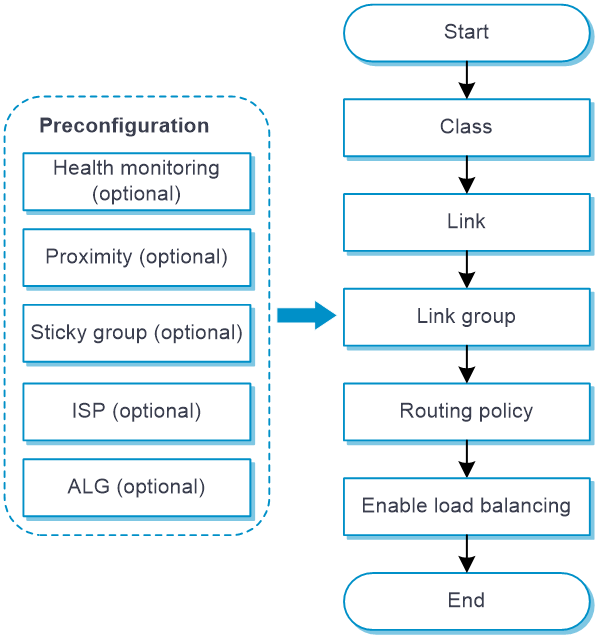
Figure-3 shows the configuration procedure for outbound link load balancing.
Figure-3 Outbound link load balancing configuration procedure
Prerequisites
Complete the following tasks before you configure this feature:
Assign IP addresses to interfaces on the
Network >Interface Configuration >Interfaces page.Configure routes on the
Network >Routing page. Make sure the routes are available.Configure links on the LB >Common Configuration >Links page.(Optional.)
Configure health monitoring on the You can specify a health monitoring probe template for a link or link group.LB >Common Configuration >Health Monitoring page.(Optional.)
Configure proximity on the LB >Common Configuration >Proximity page.(Optional.)
Configure sticky groups on the You can specify a sticky group for an IPv4 or IPv6 routing policy.LB >Common Configuration >Sticky Groups page.(Optional.)
Configure ISPs on the You can specify an ISP for match rule.LB >Common Configuration >ISP page.(Optional.) Configure ALG on the
Network >ALG page.
Quick configuration for ISP link selection
The ISP link selection configuration page fast generates outbound link load balancing configuration automatically by guiding you through the key configuration steps.
To perform ISP routing configuration:
Navigate to the
LB >Link Load Balancing >Outbound Link LB >ISP Link Selection page.Configure ISP link selection settings.
Figure-4 Quick configuration for ISP link selection
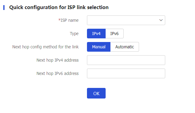
Table-1 Quick ISP link selectionconfiguration items
Item
Description
ISP name
Select an existing ISP or create a new ISP.
Type
IP address type for outbound link load balancing. Options are IPv4 and IPv6.
Next hop config method
Select a next hop configuration method:
Manual
Automatic
Next hop IPv4 address
Specify an outbound next hop IPv4 address.
The IPv4 address cannot be an IPv4 address of any interface on the device, loopback address, multicast address, broadcast address, or an address in the format of 0.X.X.X.
Next hop IPv6 address
Specify an outbound next hop IPv6 address.
The IPv6 address cannot be an IPv6 address of any interface on the device, loopback address, multicast address, link-local address, or all-zero address.
Outgoing interface
Specify an outgoing interface for the link. The outgoing interface must be an interface whose IP address can be dynamically obtained.
Click
OK . The device will automatically create associated outbound link load balancing settings.
Configure a class
An LB class classifies packets by comparing packets against specific rules. Matching packets are further processed by LB actions.
To configure a class:
Select
LB >Link L o ad Balancing >Outbound Link LB >Class .Click
Create on theClass page.Create a class.
Figure-5 Class settings
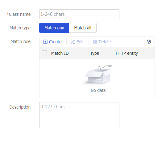
Table-2 Class configuration items
Item
Description
Class
Enter a name for the class, case insensitive.
Match type
Select a match type:
Match any —A packet matches a class if it matches any of the rules in the class.Match all —A packet matches a class if it matches all rules in the class.
Match rule
Configure a match rule. A class can contain a maximum of 65535 match rules.
Click
Create , and configure the following parameters on theCreate M atch R ule page:Rule ID —Enter a rule ID in the range of 1 to 65535. Rules are matched in ascending order of rule IDs.Type —Select a rule type. Options includeSource IPv4 address ,Source IPv6 address ,Class ,IPv4 ACL ,IPv6 ACL ,ISP ,Application group ,Destination IPv4 address ,Destination IPv6 address ,Domain name ,I n put interface ,User , andInput interface .IPv4 address —Specify the IPv4 address to match. This parameter appears only if you have selectedSource IPv4 address orDestination IPv4 address from theType list.M ask length —Specify the mask length for the IPv4 address, in the range of 0 to 32. This parameter appears only if you have selectedSource IPv4 address orDestination IPv4 address from theType list.IPv6 address —Specify the IPv6 address to match. This parameter appears only if you have selectedSource IPv6 address orDestination IPv6 address from theType list.Prefix length —Specify the prefix length for the IPv6 address, in the range of 0 to 128. This parameter appears only if you have selectedSource IPv6 address orDestination IPv6 address from theType list.Class —Specify the class to match. This parameter appears only if you have selectedClass from theType list.IPv4 ACL —Specify the IPv4 ACL to match. You can select an existing ACL or create an ACL. This parameter appears only if you have selectedIPv4 ACL from theType list.IPv 6 ACL —Specify the IPv6 ACL to match. You can select an existing ACL or create an ACL. This parameter appears only if you have selectedIPv 6 ACL from theType list.ISP —Specify the ISP to match. You can select an existing ISP or create an ISP. This parameter appears only if you have selectedISP from theType list.Application group —Specify the application group to match. You can select an existing application group or create an application group. This parameter appears only if you have selectedApplication group from theType list.Domain name —Specify the destination domain name to match. The LB device stores mappings between domain names and IP addresses in the DNS cache. If the destination IP address of an incoming packet matches an IP address in the DNS cache, the LB device queries the domain name for the IP address. If the queried domain name matches the domain name configured in a match rule, the LB device takes the LB action on the packet. This parameter appears only if you have selectedDomain name from theType list.I n put interface —Specify the input interface to match. This parameter appears only if you have selectedI n put interface from theType list.User —Specify the user or user group to match. This parameter appears only if you have selectedI n put interface from theType list. You can select an existing user or user group or create a user or user group. This parameter appears only if you have selectedUser from theType list.
Click
OK . The new match rule appears in the match rule list.
Description
Enter a description for the class.
Click
OK . The new class appears on theClass page.
Configure a link group
You can add links that contain similar functions to a link group to facilitate management. For example, you can create different link groups for different ISPs.
To configure a link group:
Select
LB >Link L o ad Balancing >Outbound Link L B >Link G roups .Click
Create on theLink G roup page.Create a link group.
Figure-6 Link group settings
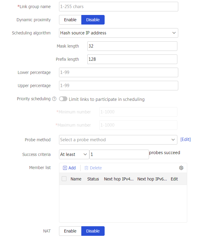
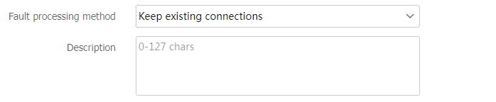
Table-3 Link group configuration items
Item
Description
Link group name
Enter a name for the link group, case insensitive.
Proximity
Enable or disable the proximity feature.
Before enabling this function, you must configure proximity parameters from the
Policies >L o ad Balancing >Common Configuration >P roximity >P roximity P arameters page. The generated proximity entries can be viewed on thePolicies >L o ad Balancing >Common Configuration >P roximity >P roximity E ntries page.Scheduling algorithm
Select a scheduling algorithm for the link group.
Weighted round-robin algorithm —Distributes DNS requests to DNS servers in a round-robin manner according to the weights of DNS servers. A DNS server with a greater weight value is assigned more DNS requests.Random algorithm —Distributes DNS requests to DNS servers randomly.Weighted least connection algorithm (least-connection) —Always assigns user requests to the link with the fewest number of weighted active connections (the number of active connections divided by weight).Weighted least connection algorithm (link group member-based) —Always assigns user requests to the link group member with the fewest number of weighted active connections (the number of active connections in the specified link group divided by weight). The weight value used in this algorithm is configured on the link group member.Source IP address hash algorithm (hash address source) —Hashes the source IP address of user requests and distributes user requests to different links according to the hash values.Source IP address and port hash algorithm (hash address source-ip-port) —Hashes the source IP address and port number of user requests and distributes user requests to different links according to the hash values.Destination IP address hash algorithm (hash address destination) —Hashes the destination IP address of user requests and distributes user requests to different links according to the hash values.Bandwidth algorithm (bandwidth) —Distributes user requests to links according to the product of the weights and remaining bandwidth of links. For example, for linkslk1 andlk2 with remaining bandwidths of 150 kbps and 250 kbps, and weights of 5 and 6 respectively, the traffic distribution ratio forlk1 andlk2 is 150 × 5 : 250 × 6, that is, 1:2.Maximum bandwidth algorithm (max-bandwidth) —Distributes user requests always to an idle link that has the largest remaining bandwidth. For example, the remaining bandwidths for linkslk1 andlk2 are 150 kbps and 250 kbps respectively, with a bandwidth difference of 100 kbps. If the requested traffic is less than 100 kbps, it will all be distributed tolk2 . If the requested traffic exceeds 100 kbps, such as 130 kbps, traffic of 100 kbps will be distributed tolk2 , and the remaining traffic of 30 kbps will be evenly distributed between the two links.Link quality algorithm —Distributes new connections to links based on the link quality. The higher the quality, the more new connections assigned to the link. The link quality is calculated by using the network delay, hop count of routes, and packet loss ratio. Support for this parameter varies by device model.
By default, the weighted round robin algorithm is used.
Lower percentage
When the percentage of available links in a primary link group is smaller than the lower percentage value, the primary link group becomes unavailable, and the backup link group takes over.
Upper percentage
When the percentage of available links in a primary link group is greater than the upper percentage value, the primary link group becomes available again to process services.
The upper percentage value must be greater than or equal to the lower percentage value.
Priority scheduling
Specify the upper limit and lower limit of links in a link group that can be scheduled. By default, all DNS servers with the highest priority in a link group are scheduled.
If the number of links with the highest priority is greater than the configured maximum number, the maximum number applies.
If the number of such links is less than the minimum number, links with lower priority are selected to meet the minimum number or until no links are available.
The link priority can be configured on the
Links page.Probe method
Specify a probe template for the link group to detect the health and availability of its links. You can configure this parameter by using one of the following methods:
Configure the parameter globally for all members in the link group on the
Link Group page, facilitating configuration and management.Configure the parameter for a specific link group member from the memeber list on the
Link Group page or on theLink s page.
The parameter setting specific to a link takes precedence over the global setting.
The probe result of a link affects the use of the corresponding link group member. The probe result of a link group member does not affect the use of the corresponding link.
You can select an existing probe template or create a probe template.
Success criteria
Specify the health monitoring success criteria for the link group.
All probes succeed —Health monitoring succeeds only when all the specified health monitoring methods succeed.At least n probes succeed —Health monitoring succeeds when a minimum of the specified number of health monitoring methods succeed. When the specified number of health monitoring methods is greater than the number of health monitoring methods on the device, health monitoring succeeds if all health monitoring methods succeed.
Member list
You can add a link to a link group in one of the following ways:
Create a link and add it to the link group.
Click
Add , and selectCreate l ink .Configure the parameters for the link (see link configuration in load balancing common configuration).
Click
OK . The new link appears in the link list.
Select an existing link.
Click
Add , and selectAdd existing link .Select a link from the list, and configure link parameters (see link configuration in load balancing common configuration).
Click
OK . The link appears in the member list.
NAT
Enable or disable NAT.
In outbound link load balancing, NAT typically needs to be disabled.
Fault processing method
Select a fault processing method:
Keep existing connections —Does not actively terminate the connection with the failed link. Keeping or terminating the connection depends on the timeout mechanism of the protocol.R edirect connections —Redirects the connection to another available link in the link group.Terminate existing connections —Terminates the connection with the failed link by sending RST packets (for TCP packets) or ICMP unreachable packets (for other types of packets).
By default, the fault processing method is
Keep existing connections .Description
Enter a description for the link group.
Click
OK . The new link group appears in theL ink G roup page.
Configure a routing policy
A routing policy associates an LB class with an LB action to guide packet forwarding.
You can specify only one class in a routing policy. The device matches packets against routing policies in their configuration order. If a packet matches a class, the device takes the associated action on the packet. If a packet matches no class, the device takes the action associated with the system-defined class named
Common procedure
Select
LB >Link L o ad Balancing >Outbound Link L B >IPv4/IPv6 Routing Policy .On the
IPv4/IPv6 Routing Policy page, configure the common settings.Figure-7 Common IPv4/IPv6 routing policy settings
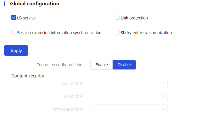
Table-4 Common configuration items
Item
Description
LB service
Enable or disable load balancing.
Link protection
Enable or disable link protection. If the traffic exceeds the bandwidth ratio of a link, the LB device distributes new traffic that does not match any sticky entries to other links.
Session extension information synchronization
Enable or disable session extension information synchronization.
Sticky entry synchronization
Enable or disable sticky entry synchronization.
Sticky entry synchronization type
Select the sticky entry synchronization type:
Intra-group synchronization —Synchronizes sticky entries to the device in the same failover group.Global synchronization —Synchronizes sticky entries to devices in all failover groups.
This function is available only when sticky entry synchronization is enabled.
Content security-Content security function
Enable or disable content security.
Support for this parameter varies by device model.
Content security-WAF profile
Specify a WAF profile to be used for Web application protection of traffic matching the virtual server.
For more information about WAF profiles, see the WAF online help.
Support for this parameter varies by device model.
Content security-IPS profile
Specify the IPS profile to be used for intrusion protection of traffic matching the virtual server.
For more information about IPS profiles, see the IPS online help.
Support for this parameter varies by device model.
Content security-Anti-virus profile
Specify the antivirus protection configuration file to be used for antivirus protection of traffic matching the virtual server.
For more information about anti-virus profiles, see the anti-virus online help.
Support for this parameter varies by device model.
Procedure for configuring an IPv4/IPv6 routing policy
Select
LB >Link L o ad Balancing >Outbound Link L B >IPv4/IPv6 Routing Policy .Click
Create on theIPv4/IPv6 Routing Policy page.Create an IPv4/IPv6 routing policy.
Figure-8 IPv4/IPv6 routing policy settings
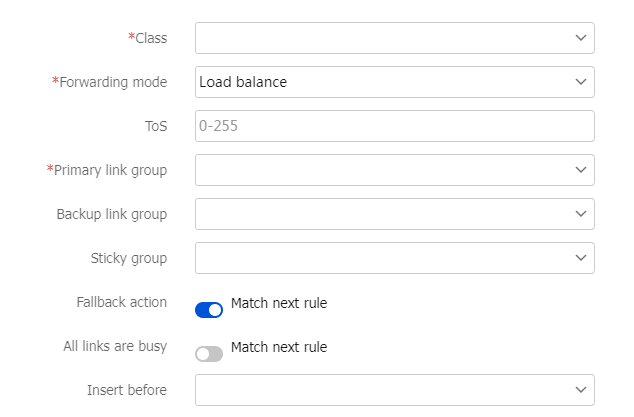
Table-5 IPv4/IPv6 routing policy configuration items
Item
Description
Class
Select an existing class or create a class.
Forwarding action
Select a forwarding action:
Load balance
Discard
Forward
ToS
Enter the ToS field value in IP packets sent to the DNS server.
IPv6 routing policies do not support this parameter.
Primary link group
Select an existing link group or create a link group.
When the primary link group is available (contains available links), the device forwards packets through the primary link group. When the primary link group is not available, the device forwards packets through the backup link group.
Backup link group
Select an existing link group or create a link group.
Sticky group
Select an existing sticky group or create a sticky group.
Only address-port sticky groups are supported.
Fallback action
Specify that the next rule is matched when a failure to find a link occurs.
This parameter does not take effect on SIP virtual servers.
Busy action
Specify that the next rule is matched when all links are busy.
Insert before
Specify an existing routing policy before which the new policy is inserted.
Click
OK . The new routing policy appears on theIPv4/IPv6 Routing Policy page.