IRF advanced settings
This help contains the following topics:
Introduction
IRF advanced settings are IRF high availability (HA) settings. IRF HA enables two IRF member devices to back up each other dynamically to ensure forwarding service continuity upon failure on one of the devices. For more information about IRF, see the related IRF documentation.
IRF HA
Mechanisms
IRF HA provides the following services:
Service backup —Backs up the data and entries of services between the two devices. This minimizes the forwarding interruption time when traffic is switched from one device to the other.Traffic migration —Switches traffic from one device to the other by using a redundancy group. A redundancy group allows traffic to enter and leave the HA system through the same device. The redundancy group works with Track to detect uplink and downlink failures. When detecting a failure, the redundancy group switches all its members from the failed device to the other device.
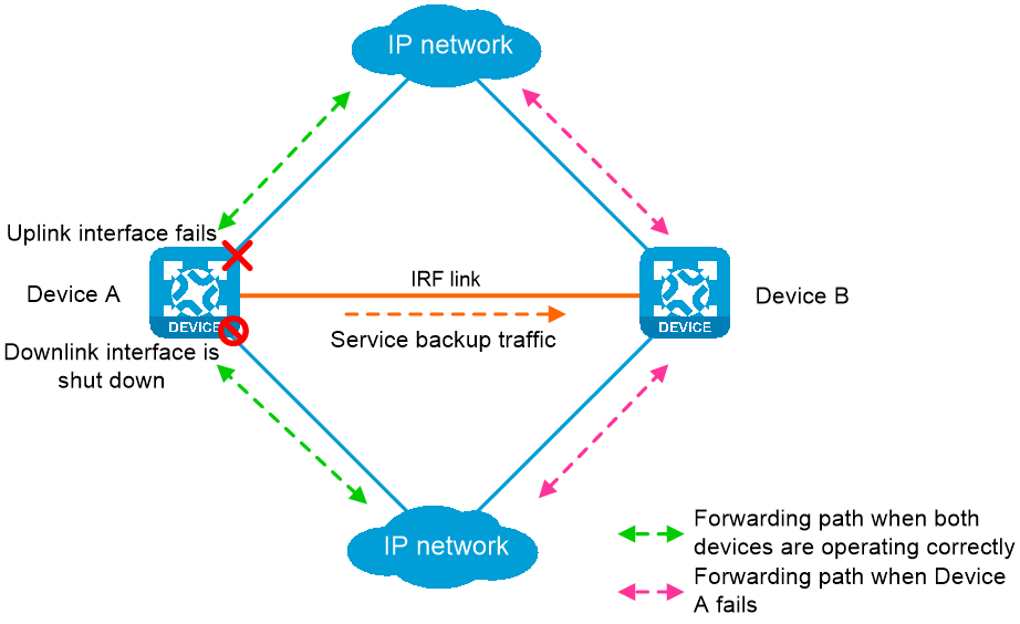
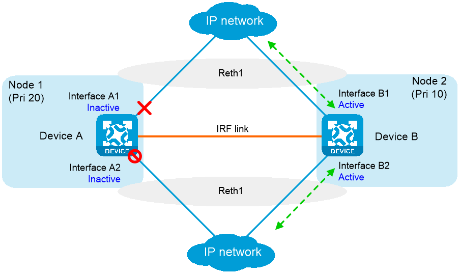
IRF HA works as follows, as shown in Figure-1
When both devices are working correctly, Device A forwards traffic, and service data and entries are backed up from Device A to Device B.
Track detects that the uplink interface of Device A fails.
The redundancy group shuts down the downlink interface of Device A.
Traffic is switched to Device B for forwarding. Because Device B already has service data and entries, traffic migration almost has no impact on the services.
Operating modes
IRF HA supports the following modes:
Active/standby mode —Only one device processes services.Dual-active mode —Both devices process services.
Redundancy groups
Redundancy group nodes
A redundancy group contains two nodes. A redundancy group node can act as the primary or secondary node. Only the primary node can forward traffic. When both nodes are working correctly, only interfaces and CPUs on the primary node are processing traffic (such as forwarding packets and creating session entries). The secondary node acts as a backup and does not process traffic as long as the primary node is working correctly.
Redundancy group nodes are associated with physical devices in a cluster by member IDs. The primary node can be the master device or standby device in a cluster. Typically, the primary node is the master device.
Member interfaces
You can assign physical interfaces to a redundancy group by binding them to their respective redundancy group nodes.
For symmetric traffic switchover, you must bind a minimum of one downlink interface and a minimum of one uplink interface with each node of the redundancy group.
The state of the member physical interfaces changes with the state of the redundancy group nodes. Only the member interfaces on the primary node can forward traffic.
As shown in Figure-2, Port 1 and Port 2 are on Node 1, and Port 3 and Port 4 are on Node 2. When Node 1 is in primary state, Port 1 and Port 2 are up to forward traffic, while Port 3 and Port 4 are shut down by the Reth module.
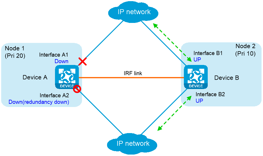
When Port 1 goes down, the Reth module places Node 1 in secondary state and shuts down Port 2. Node 2 changes to the primary state, and Port 3 and Port 4 come up to forward traffic, as shown in Figure-3
Figure-2 States of the member interfaces when both nodes are operating correctly
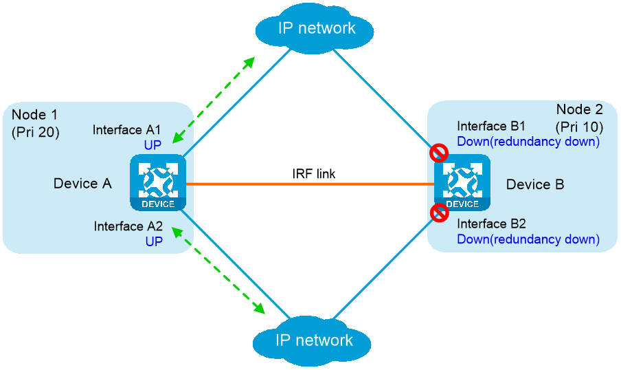
Figure-3 States of the member interfaces after a switchover
Reth interfaces
To use Reth interfaces for symmetric forwarding, you must assign two Reth interfaces to a redundancy group: one for uplink traffic and the other for downlink traffic. The Reth interfaces must meet the following requirements:
The Reth interface for uplink traffic contains one uplink port on each redundancy group node.
The Reth interface for downlink traffic contains one downlink port on each redundancy group node.
The high-priority member of each Reth interface belongs to the high-priority node.
The state of each Reth interface's members depends on the state of the redundancy group nodes.
When the high-priority node is in primary state, the high-priority member is active.
When the low-priority node is in primary state, the low-priority member is active.
As shown in Figure-4, redundancy group 1 contains Reth 1 for uplink traffic and Reth 2 for downlink traffic. Reth 1 contains Port 1 (on Node 1) and Port 3 (on Node 2). Reth 2 contains Port 2 (on Node 1) and Port 4 (on Node 2).
When Node 1 is in primary state, Port 1 in Reth 1 and Port 2 in Reth 2 are active to forward uplink and downlink traffic, respectively.
When Port 1 fails, the Reth module places Node 1 in secondary state and shuts down Port 2, as shown in Figure-5. Node 2 changes to the primary state, and Port 3 and Port 4 become active to forward uplink and downlink traffic.
Figure-4 States of each Reth interface's members when both nodes are operating correctly
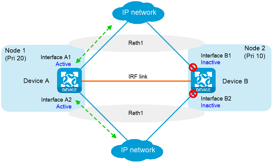
Figure-5 States of each Reth interface's members after a switchover
Failover and fallback
In a redundancy group, one node is in primary state, and the other node is in secondary state. Only the primary node forwards traffic. When the primary node fails, the redundancy group switches over to the secondary node. This mechanism ensures path symmetry for traffic.
A redundancy group performs a switchover as follows:
When both redundancy group nodes are operating correctly, the redundancy group forwards traffic through the primary node and backs up services and data to the secondary node.
When the upstream interface on the primary node fails, the redundancy group shuts down the downstream interface on the primary node and switches traffic over to the secondary node.
When the primary node recovers, the redundancy group switches traffic back to the primary node.
Redundancy group switchovers include automatic switchovers and manual switchovers.
Automatic switchover —A redundancy group cooperates with the Track module to monitor link and interface status for automatic switchovers.Manual switchover —You issue a manual switchover request.
When a switchover is triggered, traffic is not migrated immediately. Whether traffic is migrated depends on the status of the primary node and the preemption delay timer.
Preemption delay timer
The preemption delay timer specifies the delay for a switchover back to the high-priority node. The preemption delay timer starts when the switchover is triggered. The redundancy group performs the switchover only after the timer expires. The delay allows the system to process events (such as interface state changes) required for the switchover. If the high-priority node is not ready when this timer expires, the switchover is not performed.
vSystem support information
Support of non-default vSystems for this feature depends on the device model. This feature is available on the Web interface only if it is supported.
Restrictions and guidelines
Do not assign management interfaces to a redundancy group or Reth interface. If you do so, remote management connections are interrupted if the redundancy group or Reth interface is deleted.
In dual-active mode, devices support only the flow-based policy for flow classification.
In dual-active mode, devices do not support AFT.
Configure IRF HA
Prerequisites
Before you configure IRF HA on two devices, make sure they use the same software and hardware, and have formed an IRF fabric.
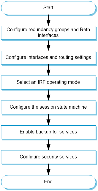
IRF HA configuration flow
Figure-6 IRF HA configuration flow chart
Configure redundancy groups
Click the
System tab.In the navigation pane, select
Virtualization Advanced Settings >IRF Advanced Settings .The
IRF Advanced Settings Click
Redundancy groups .Figure-7 Redundancy groups

Click
Create , configure the redundancy group name, and clickOK .Figure-8 Creating a redundancy group

Configure the redundancy group and Reth interfaces. For more information about the related parameters, see
the following tables: Figure-9 Adding devices to a redundancy group
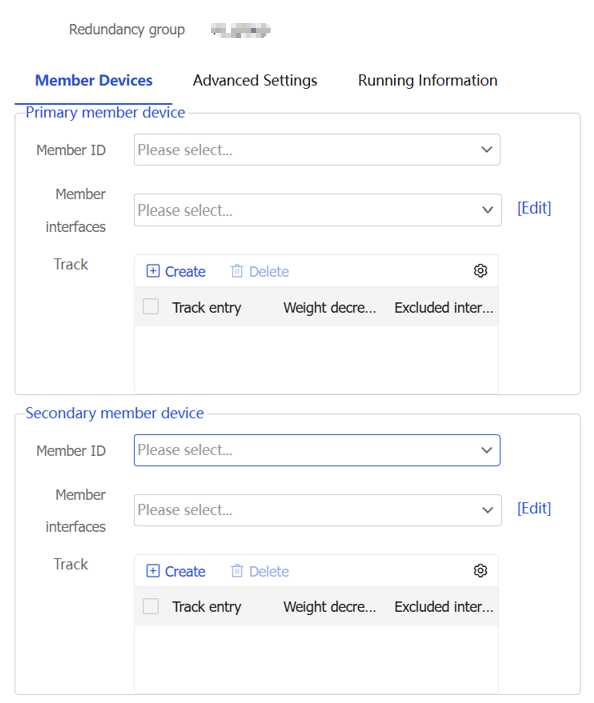
Figure-10 Adding a track entry
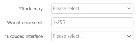
Table-1 Member device parameters in a redundancy group
Parameter
Description
Member Devices
Specify a maximum of two member devices for the redundancy group. One member device is the primary device, and the other is the secondary device. Typically, the primary device is the IRF master.
Member ID
Set the IRF member ID of each device.
Member interfaces
Specify the member interfaces of the redundancy group. Configure member interfaces when the upstream and downstream devices of the HA system run a dynamic routing protocol. In this scenario, you must configure the uplink and downlink physical Ethernet interfaces of the member devices as member interfaces of the redundancy group.
Reth interfaces
Configure Reth interfaces. Use Reth interfaces when the upstream and downstream devices of the HA system do not run a dynamic routing protocol. For more information, see
the Reth interface configuration step. You must configure a minimum of two Reth interfaces, one containing uplink interfaces and the other containing downlink interfaces.Track
Associate track entries with the redundancy group to trigger redundancy group member switchover.
When you associate track entries, following these restrictions and guidelines:
To ensure effective configuration, create a track entry before you associate it with a redundancy group.
When you configure the
Excluded Interface parameter, you must specify the tracked interface if the interface has one of the following roles:Member interface of a member device the redundancy group.
Member of a Reth interface in the redundancy group.
Click the
Advanced Settings tab, and then configure the parameters as needed.Figure-11 Advanced settings
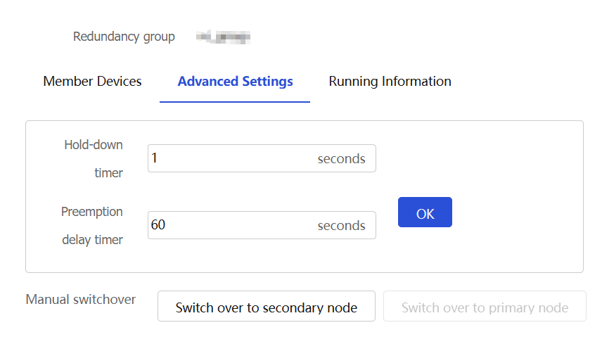
Table-2 Advanced settings for a redundancy group
Parameter
Description
Hold-down timer
Set the hold-down timer. This timer specifies the minimum interval between two switchovers to prevent frequent switchovers.
Preemption delay timer
Set the preemption delay timer. This timer specifies the delay before a switchback.
Manual switchover
Manually perform a switchover or switchback.
Click
Create in theReth interfaces area.You can configure multiple Reth interfaces in a redundancy group. Typically, you must configure a minimum of two Reth interfaces. One Reth interface contains the uplink interfaces on the member devices, and the other contains the downlink interfaces on the member devices.
Configure the Reth interface as needed, and then click
OK . For more information about the related parameters, seethe following table. Figure-12 Reth interfaces
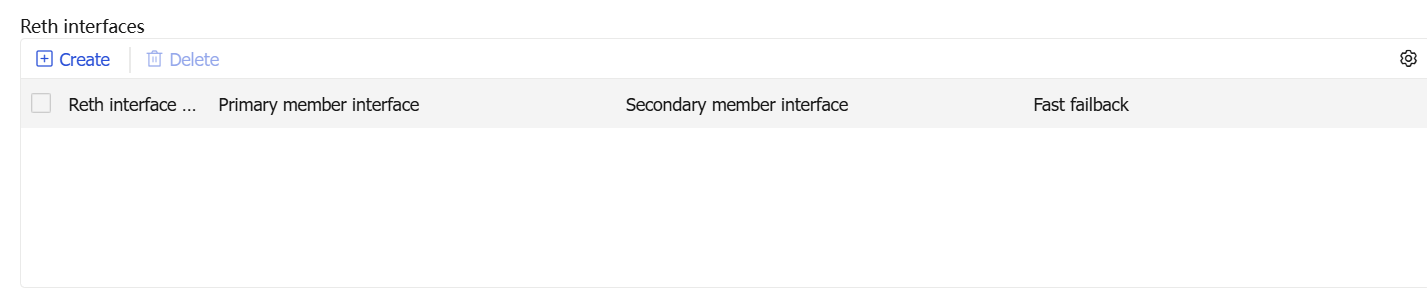
Figure-13 Adding a Reth interface
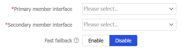
Table-3 Reth interface parameters
Parameter
Description
Primary member interface
Select an uplink or downlink interface on the primary member device.
Secondary member interface
Select an uplink or downlink interface on the secondary member device.
Fast failback
Set the status of the fast failback feature. Fast failback reduces the failback time when traffic is switched from the secondary member interface back to the primary member interface. This feature sets the physical link state of the primary member interface to Up when that interface is in inactive state. Only the data link layer state of that interface is set to
Down .Click
OK to complete the redundancy group configuration.
Configure HA on the IRF fabric
Click the
System tab.In the navigation pane, select
Virtualization Advanced Settings >IRF Advanced Settings .The
IRF Advanced Settings Figure-14 IRF advanced settings
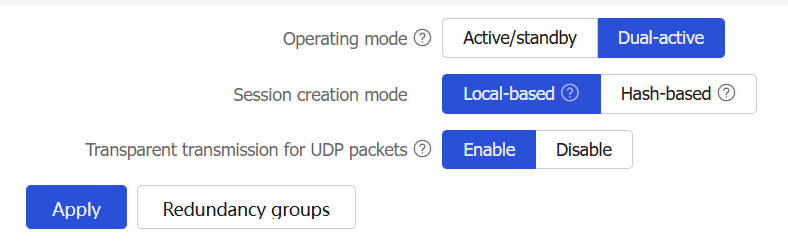
Configure IRF HA. For more information about related-parameters, see
Parameter
Description
Operating mode
Set the operating mode of IRF HA.
Active/standby —The primary device processes services, and the secondary device stands by.Dual-active —Both the primary and secondary devices process services.
Session creation mode
Set the session creation mode. To balance the service load on the devices, you can use one of the following session creation modes:
Hash-based session creation —A session is created on the device to which its first packet is relayed according to the hash result. The device where a session is created might not be the device that receives the traffic. This mode applies if traffic is unevenly distributed among the devices.Local-based session creation —A session is created on the device where the first packet of the session arrives. This mode applies if traffic is evenly distributed among the devices.
This parameter is available only in dual-active mode.
Transparent transmission for UDP packets
Set the status of transparent transmission for UDP packets.
This feature allows a device to relay UDP packets that do not match any sessions to the other device in the HA system. If the UDP packets also do not match any sessions on the other device, a new session is created locally.
This parameter is available only in dual-active mode.
Click
Apply to complete configuring the IRF advanced settings.