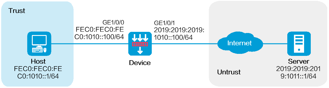
As shown in Figure 1, configure source address translation on the device to allow internal users to access the server in the external network.
This configuration example was created and verified on F9900 of the F5000-AI120 device.
This feature is mutually exclusive with global NAT.
Assign IP addresses to interfaces and add the interfaces to security zones.
# On the top navigation bar, click Network.
# From the navigation pane, select Interface Configuration > Interfaces.
# Click the Edit icon for GE1/0/1.
# In the dialog box that opens, configure the interface:
Select the Untrust security zone.
On the IPv6 Address tab, enter the IPv6 global unicast address and prefix of the interface. In this example, enter 2019:2019:2019:1010::100/64.
Retain the default configuration for the rest of parameters.
Click OK.
# Add GE1/0/0 to the Trust security zone and set its IPv6 global unicast address to FEC0:FEC0:FEC0:1010::100/64 in the same way you configure GE1/0/1.
Create a route.
The following configuration example involves only static route for illustration. To apply a dynamic route, you can configure a dynamic routing protocol as needed.
# On the top navigation bar, click Network.
# From the navigation pane, select Routing > Static Routing > IPv6 Static Routing.
# Click Create.
# In the dialog box that opens, create an IPv6 static route.
Enter 2019:2019:2019:1011::1 as the destination address.
Set the prefix length to 64.
Enter 2019:2019:2019:1010::101 as the next hop.
Retain the default configuration for the rest of parameters.
# Click Apply.
3. Create a security policy.
# On the top navigation bar, click Policies.
# From the navigation pane, select Security Policies > Security Policies.
# Click Create.
# In the dialog box that opens, configure a security policy to allow packets from the internal network to pass through.
Enter policy name Secpolicy.
Select source zone Trust.
Select destination zone Untrust.
Select type IPv6.
Select action Permit.
Enter FEC0:FEC0:FEC0:1010::1 as the source address.
Enter 2019:2019:2019:1011::1 as the destination address.
Retain the default configuration for the rest of parameters.
# Click Apply.
4. Configure NPTv6.
# On the top navigation bar, click Policies.
# From the navigation pane, select Interface NAT > IPv6.
# Click Create.
# Create a prefix translation mapping, as shown in Figure 2.
Figure 2 Creating a NAT66 prefix translation mapping
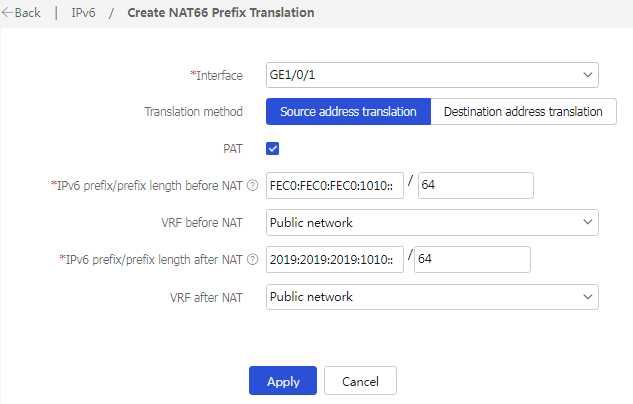
# Click Apply.
1. Verify that the host can successfully ping the server in the external network.
C:\Users\abc>ping 2019:2019:2019:1011::1
Pinging 2019:2019:2019:1011::1 with 32 bytes of data:
Reply from 2019:2019:2019:1011::1: bytes=32 time<1ms TTL=253
Reply from 2019:2019:2019:1011::1: bytes=32 time<1ms TTL=253
Reply from 2019:2019:2019:1011::1: bytes=32 time<1ms TTL=253
Reply from 2019:2019:2019:1011::1: bytes=32 time<1ms TTL=253
Ping statistics for 2019:2019:2019:1011::1:
Packets: Sent = 4, Received = 4, Lost = 0 (0% loss),
Approximate round trip times in milli-seconds:
Minimum = 0ms, Maximum = 0ms, Average = 0ms
2. Verify that a session is generated when the host accesses the server.
# On the top navigation bar, click Monitor.
# From the navigation pane, select Network Traffic > Sessions.
Figure 3 Session list
