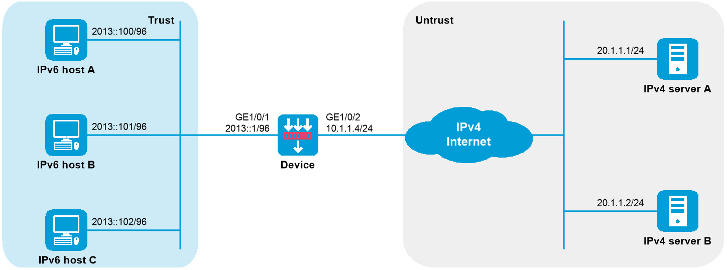
As shown in Figure 1, a company upgrades the network to IPv6 and has IPv4 addresses from 10.1.1.1 to 10.1.1.3.
To allow IPv6 hosts on subnet 2013::/96 to access the IPv4 Internet, configure the following AFT policies on the device:
Configure a NAT64 prefix to translate IPv4 addresses of IPv4 servers to IPv6 addresses.
Configure an IPv6-to-IPv4 source address dynamic translation policy to translate source IPv6 addresses of IPv6-initiated packets to IPv4 addresses in the range of 10.1.1.1 to 10.1.1.3.
This configuration example was created and verified on F9900 of the F5000-AI120 device.
Assign IP addresses to interfaces and add the interfaces to security zones.
# On the top navigation bar, click Network.
# From the navigation pane, select Interface Configuration > Interfaces.
# Click the Edit icon for GE1/0/1.
# In the dialog box that opens, configure the interface as follows:
Select the Trust security zone.
On the IPv6 Address tab, set the IPv6 address/prefix length to 2013::1/96.
Use the default settings for other parameters.
# Click OK.
# Add GE1/0/2 to the Untrust security zone and set its IP address to 10.1.1.4/24 in the same way you configure GE1/0/1.
Configure settings for routing:
This example configures a static route. If dynamic routes are required, configure a dynamic routing protocol.
# On the top navigation bar, click Network.
# From the navigation pane, select Routing > Static Routing.
# On the IPv4 Static Routing tab, click Create.
# In the dialog box that opens, perform the following tasks:
Specify the destination IP address as 20.1.1.0.
Set the mask length to 24.
Specify the next-hop address as 10.1.1.100.
Use the default settings for other parameters.
# Click Apply.
Configure security policies:
# On the top navigation bar, click Policies.
# From the navigation pane, select Security Policies.
# On the Security Policies tab, click Create.
# On the page that opens, perform the following tasks to create an IPv4 security policy:
In the Name field, enter aftlocalout.
From the Source zone list, select Local.
From the Destination zone list, select Untrust.
Select IPv4 for the Type field.
Select Permit for the Action field.
Specify source IPv4 addresses as the IP addresses of the hosts. In this example, the addresses are 10.1.1.1, 10.1.1.2, and 10.1.1.3.
Specify destination IPv4 addresses as the IP addresses of the servers. In this example, the addresses are 20.1.1.1 and 20.1.1.2.
Use the default settings for other parameters.
# Click Apply.
# Perform the following tasks to create an IPv6 security policy:
In the Name field, enter aftlocalin.
From the Source zone list, select Trust.
From the Destination zone list, select Local.
Select IPv6 for the Type field.
Select Permit for the Action field.
Specify the source IPv6 address as 2013::/96.
Specify destination IPv6 addresses as 2012::1401:101 and 2012::1401:102.
Use the default settings for other parameters.
# Click Apply.
Configure a NAT address group:
# On the top navigation bar, click Objects.
# From the navigation pane, select Object Groups > IPv4 Address Object Groups.
# Click Create.
# Create a NAT address group, as shown in Figure 2.
Figure 2 Creating an IPv4 address object group
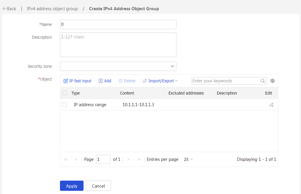
# Click Apply.
Create a policy-based NAT rule:
# Configure an IPv6-to-IPv4 source address dynamic translation policy to translate source IPv6 addresses in packets sent from 2013::/96 to IPv4 addresses in the range of 10.1.1.1 to 10.1.1.3.
# On the top navigation bar, click Policies.
# From the navigation pane, select Policy-based NAT.
# Click the chevron icon next to Create SNAT, select Create SNAT+DNAT, and then click the NAT64 tab.
# Select the V6toV4 translation method.
# Create a policy-based NAT rule, as shown in Figure 3.
Figure 3 Creating a policy-based NAT rule
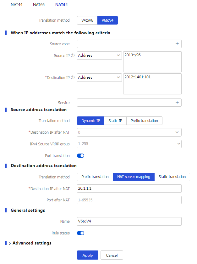
# Click Apply.
Enable AFT on the interfaces connected to the IPv6 network and IPv4 Internet, respectively.
# Access the CLI of the device, enter the view of each interface, and then execute the aft enable command on each interface.
# Verify the connectivity between IPv6 hosts and IPv4 servers. This example pings IPv4 server A from IPv6 host A.
D:\>ping 2012::20.1.1.1
Pinging 2012::20.1.1.1 with 32 bytes of data:
Reply from 2012::20.1.1.1: time=3ms
Reply from 2012::20.1.1.1: time=3ms
Reply from 2012::20.1.1.1: time=3ms
Reply from 2012::20.1.1.1: time=3ms
# Display detailed information about IPv6 AFT sessions on the device.
[Device] display aft session ipv6 verbose
Initiator:
Source IP/port: 2013::100/0
Destination IP/port: 2012::1401:0101/32768
VPN instance/VLAN ID/Inline ID: -/-/-
Protocol: IPV6-ICMP(58)
Inbound interface: GigabitEthernet1/0/1
Source security zone: Trust
Responder:
Source IP/port: 2012::1401:0101/0
Destination IP/port: 2013::100/33024
VPN instance/VLAN ID/Inline ID: -/-/-
Protocol: IPV6-ICMP(58)
Inbound interface: GigabitEthernet1/0/2
Source security zone: Local
State: ICMPV6_REPLY
Application: ICMP
Rule ID: -/-/-
Rule name:
Start time: 2014-03-13 08:52:59 TTL: 23s
Initiator->Responder: 4 packets 320 bytes
Responder->Initiator: 4 packets 320 bytes
Total sessions found: 1
# Display detailed information about IPv4 AFT sessions on the device.
[Device] display aft session ipv4 verbose
Initiator:
Source IP/port: 10.1.1.1/1025
Destination IP/port: 20.1.1.1/2048
DS-Lite tunnel peer: -
VPN instance/VLAN ID/Inline ID: -/-/-
Protocol: ICMP(1)
Inbound interface: GigabitEthernet1/0/1
Source security zone: Local
Responder:
Source IP/port: 20.1.1.1/1025
Destination IP/port: 10.1.1.1/0
DS-Lite tunnel peer: -
VPN instance/VLAN ID/Inline ID: -/-/-
Protocol: ICMP(1)
Inbound interface: GigabitEthernet1/0/2
Source security zone: Untrust
State: ICMP_REPLY
Application: ICMP
Rule ID: 0
Rule name: aftlocalout
Start time: 2014-03-13 08:52:59 TTL: 27s
Initiator->Responder: 4 packets 240 bytes
Responder->Initiator: 4 packets 240 bytes