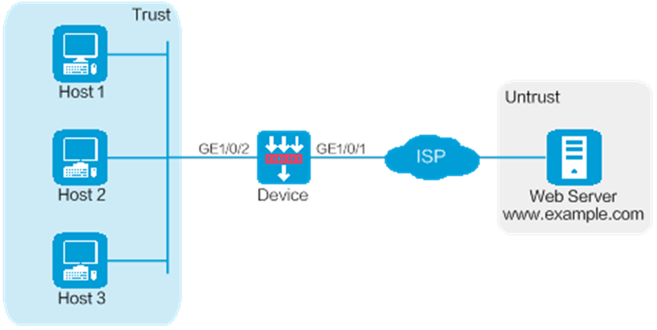
As shown in Figure 1, Device is deployed at the egress of the enterprise network. The enterprise applies for a PPPoE account with the username as pppoeuser1 and password as 123456 from the ISP. Configure PPPoE for users in the enterprise network to access the Web server with the address www.example.com in the Internet.
This configuration example was created and verified on F9900 of the F5000-AI120 device.
When the device acts as a DHCP server, for the DHCP clients to obtain IP addresses, you must permit the traffic from the security zone where the DHCP-enabled interfaces reside to the local security zone. In this example, you must permit the traffic from security zone Trust to security zone Local.
Configure PPPoE.
# On the top navigation bar, click System.
# From the navigation pane, select Configuration Wizard > Internet Access. The page as shown in Figure 2 opens.
Figure 2 Internet Access
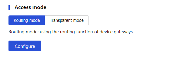
# Select Routing mode, and click Configure. Configure the WAN interface parameters as shown in Figure 3.
Figure 3 WAN interface configuration
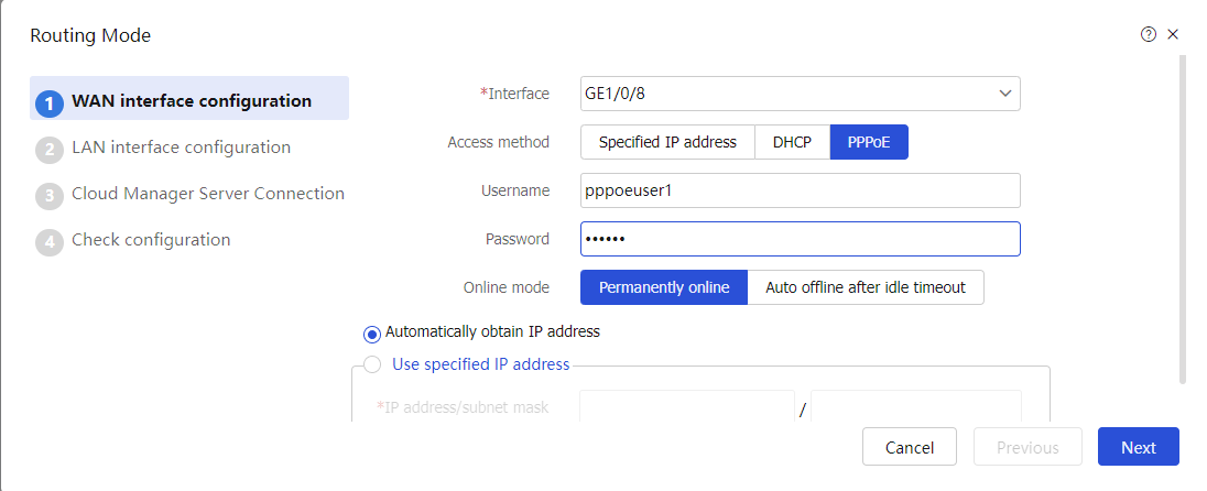
# Click Next. Configure the LAN interface parameters as shown in Figure 4.
Figure 4 LAN interface configuration
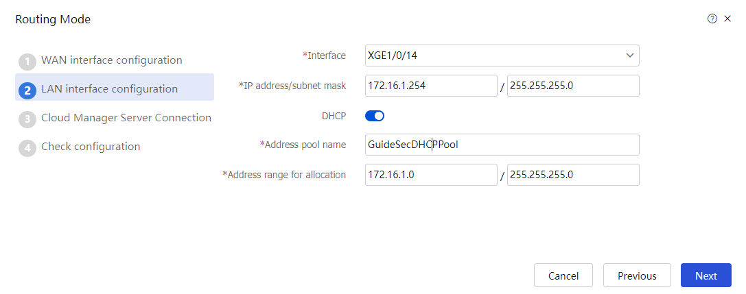
# Click Next. Skip the cloud security configuration and click Next to verify the configuration.
Figure 5 Verifying the configuration
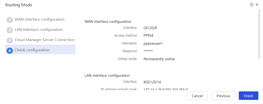
# Verify that the configuration is correct, and then click Finish.
Configure a security policy.
After PPPoE is configured, the system automatically creates a security policy named GuideSecPolicy.
# On the top navigation bar, click Policies.
# From the navigation pane, select Security Policies > Security Policies. The Security Policies page as shown in Figure 6 opens.
Figure 6 Security policy configuration page
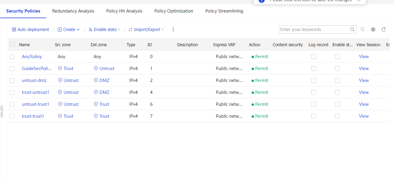
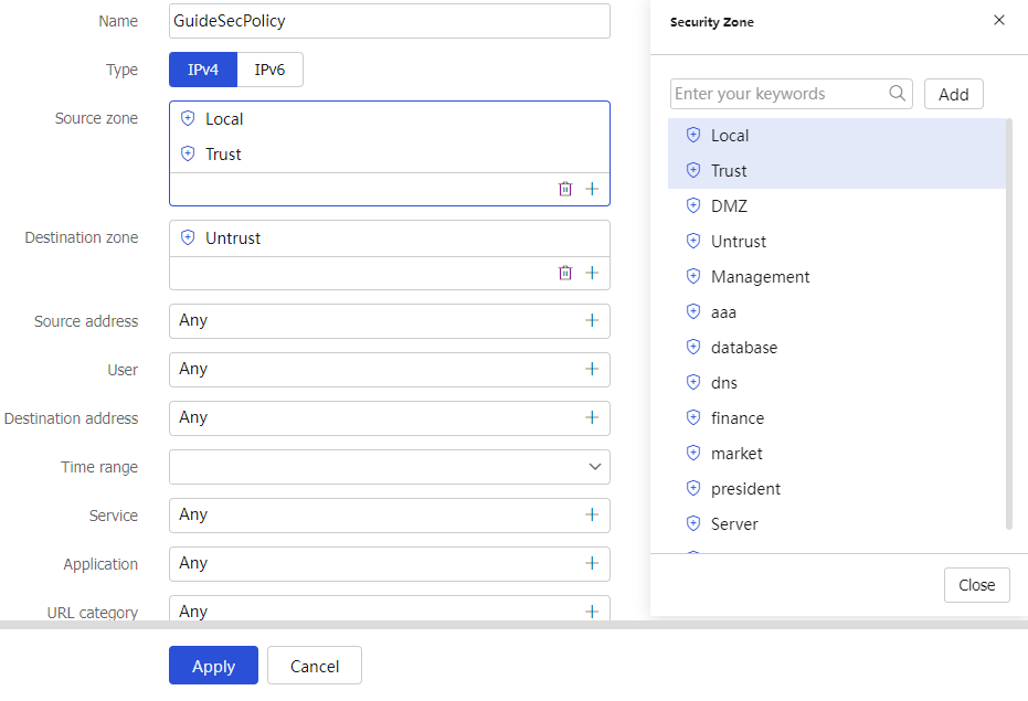
# Select the security policy GuideSecPolicy, and click the icon in the Edit column. Add the source zone Local, and add the destination zones Trust and Local, as shown in Figure 7.
Figure 7 Adding a security policy
Configure DHCP.
# On the top navigation bar, click Network.
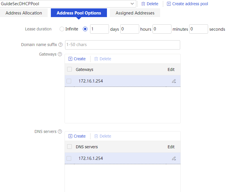
# From the navigation pane, select DHCP > DHCP Address Pools.
# Click the Address Pool Options tab. Configure parameters as shown in Figure 8.
Configure the DNS service.
# On the top navigation bar, click Network.
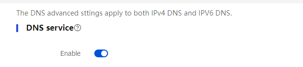
# From the navigation pane, select DNS > Advanced Settings. On the page as shown in Figure 9, enable the DNS service.
Figure 9 DNS service
# Configure the hosts to automatically obtain IP addresses.
View the address information that a host obtains.
C:\>ipconfig /all
Ethernet adapter Local Area Connection:
Connection-specific DNS Suffix..........:
Description.......................: Intel(R) 82579LM Gigabit Network Connection
Physical Address....................: E8-39-35-5C-92-B8
DHCP Enabled ................: Yes
Autoconfiguration Enabled...............: Yes
Link-local IPv6 address...........: fe80::b8dd:d091:201a:6db2%13(Preferred)
IPv4 Address...................: 172.16.1.3(Preferred)
Subnet Mask.....................: 255.255.255.0
Lease Obtained................: May 25, 2017 14:01:30
Lease Expires................: May 26, 2017 14:01:30
Default Gateway.....................: 172.16.1.254
DHCP Server..................: 172.16.1.254
DHCPv6 IAID.................: 384317749
DHCPv6 Client DUID...........: 00-01-00-01-1F-B4-A3-F5-B8-A3-86-6F-0F-02
DNS Servers...................: 172.16.1.254
NetBIOS over Tcpip...........: Enabled
Verify that a host can ping the server address www.example.com.
C:\>ping www.example.com
Ping www.example.com [192.168.100.201]: 32 data bytes
32 bytes from 192.168.100.201: time<1ms TTL=253
32 bytes from 192.168.100.201: time<1ms TTL=253
32 bytes from 192.168.100.201: time<1ms TTL=253
32 bytes from 192.168.100.201: time<1ms TTL=253
--- Ping statistics for 192.168.100.201 ---
4 packets transmitted, 4 packets received, 0.0% packet loss