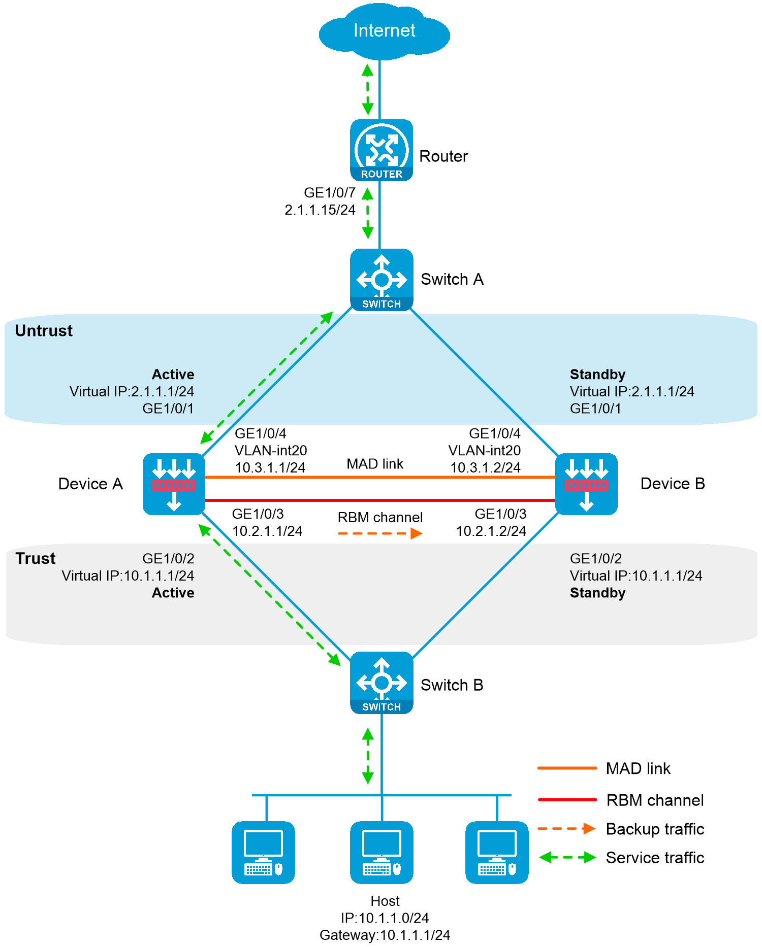
As shown in the following figure, Device A and Device B are border security devices connected to the internal network and the Internet. To improve service stability, use the two devices to form an RBM system, with Device A as the primary device, and Device B as the secondary device. Assign the same virtual IP address (also known as floating IP address) to the same numbered service interfaces on the devices. The virtual IP addresses on the service interfaces will then be associated with and managed by RBM. Set up MAD to avoid address conflicts between the two devices when the hot backup channel is disconnected. When Device A or its attached link fails, Device B takes over to ensure service continuity.
Figure 1 Network diagram
This configuration example was created and verified on F9900 of the F5000-AI120 device.
Before you set up an RBM system, verify that the following hardware settings are consistent on the candidate member devices:
Device model.
Number and type of management interfaces of active and standby devices, service interfaces, and interfaces for setting up the RBM channels. Do not use one interface for multiple purposes.
Location, number, and type of disks. A device not with disks installed has small log storage and do not support some types of logs or reports.
Before you set up an RBM system, verify that the following software settings are consistent on the candidate member devices:
Software environment and version, including boot packages, system packages, feature packages, and patches.
Licensed signature libraries and features, such as signature library types, signature library version, validation time, and number of licensed resources.
Interface numbers.
Type, speed, and number of the interfaces for setting up the RBM channels. As a best practice, use aggregate interfaces.
Aggregate interface numbers and aggregation member port numbers.
Security zone configuration on the interfaces at the same location.
Multi-CPU packet distribution policy (configured with the forwarding policy command).
# Create VLAN 10 on Switch A, and configure the interfaces that connect Switch A to Device A, Device B, and Router as access ports, and then assign the ports to VLAN 10.
# Add interfaces to VLANs and set the link type according to the network diagram as follows.
<SwitchA> system-view
[SwitchA] vlan 10
[SwitchA-vlan10] quit
[SwitchA] interface gigabitethernet 1/0/1
[SwitchA-GigabitEthernet1/0/1] port access vlan 10
[SwitchA-GigabitEthernet1/0/1] quit
[SwitchA] interface gigabitethernet 1/0/2
[SwitchA-GigabitEthernet1/0/2] port access vlan 10
[SwitchA-GigabitEthernet1/0/2] quit
[SwitchA] interface gigabitethernet 1/0/3
[SwitchA-GigabitEthernet1/0/3] port access vlan 10
[SwitchA-GigabitEthernet1/0/3] quit
# Create VLAN 10 on Switch B, and configure the interfaces that connect Switch B to Device A, Device B, and Host as access ports, and then assign the ports to VLAN 10.
# Add interfaces to VLANs and set the link type according to the network diagram as follows.
<SwitchB> system-view
[SwitchB] vlan 10
[SwitchB-vlan10] quit
[SwitchB] interface gigabitethernet 1/0/1
[SwitchB-GigabitEthernet1/0/1] port access vlan 10
[SwitchB-GigabitEthernet1/0/1] quit
[SwitchB] interface gigabitethernet 1/0/2
[SwitchB-GigabitEthernet1/0/2] port access vlan 10
[SwitchB-GigabitEthernet1/0/2] quit
[SwitchB] interface gigabitethernet 1/0/3
[SwitchB-GigabitEthernet1/0/3] port access vlan 10
[SwitchB-GigabitEthernet1/0/3] quit
Assign IPv4 addresses to interfaces:
# Assign an IPv4 address to GigabitEthernet 1/0/1.
<Router> system-view
[Router] interface gigabitethernet 1/0/7
[Router-GigabitEthernet1/0/7] ip address 2.1.1.15 255.255.255.0
[Router-GigabitEthernet1/0/7] quit
# Assign IP addresses to other interfaces in the same way according to the network diagram. (Details not shown.)
Configure route settings for network connectivity.
This example takes static route configuration as an example. Configure route settings according to the actual network requirements.
# Configure static route settings according to the network diagram. In this example, specify 2.1.1.1 as the next hop for traffic to the internal network, and specify 3.1.1.15 as the next hop for traffic to the Internet.
[Router] ip route-static 10.1.1.0 255.255.255.0 2.1.1.1
[Router] ip route-static 0.0.0.0 0.0.0.0 3.1.1.15
Assign IPv4 addresses to interfaces:
# Assign an IPv4 address to each interface according to the network diagram as follows (assign floating addresses for service interfaces GigabitEthernet 1/0/1 and GigabitEthernet 1/0/2).
<DeviceA> system-view
[DeviceA] interface gigabitethernet 1/0/1
[DeviceA-GigabitEthernet1/0/1] ip address 2.1.1.1 255.255.255.0 float
[DeviceA-GigabitEthernet1/0/1] quit
[DeviceA] interface gigabitethernet 1/0/2
[DeviceA-GigabitEthernet1/0/2] ip address 10.1.1.1 255.255.255.0 float
[DeviceA-GigabitEthernet1/0/2] quit
[DeviceA] interface gigabitethernet 1/0/3
[DeviceA-GigabitEthernet1/0/3] ip address 10.2.1.1 255.255.255.0
[DeviceA-GigabitEthernet1/0/3] quit
Add interfaces to security zones.
# Add interfaces to security zones according to the network diagram.
[DeviceA] security-zone name untrust
[DeviceA-security-zone-Untrust] import interface gigabitethernet 1/0/1
[DeviceA-security-zone-Untrust] quit
[DeviceA] security-zone name trust
[DeviceA-security-zone-Trust] import interface gigabitethernet 1/0/2
[DeviceA-security-zone-Trust] quit
Configure route settings for network connectivity:
This example takes static route configuration as an example. Configure route settings according to the actual network requirements.
# Configure a static route for Layer 3 connectivity between the internal and external networks according to the network diagram. The next hop for the static route to the external network is 2.1.1.15.
[DeviceA] ip route-static 0.0.0.0 0.0.0.0 2.1.1.15
Configure security policy settings to permit specific service packets:
Perform this task only on the primary device. After the RBM system is set up, the secondary device automatically synchronizes its security policy configuration with the primary device.
# Create a security policy rule named trust-untrust to allow internal network users to access the Internet and prevent Internet users to access the internal network.
[DeviceA] security-policy ip
[DeviceA-security-policy-ip] rule name trust-untrust
[DeviceA-security-policy-ip-3-trust-untrust] source-zone trust
[DeviceA-security-policy-ip-3-trust-untrust] destination-zone untrust
[DeviceA-security-policy-ip-3-trust-untrust] source-ip-subnet 10.1.1.0 24
[DeviceA-security-policy-ip-3-trust-untrust] action pass
[DeviceA-security-policy-ip-3-trust-untrust] quit
[DeviceA-security-policy-ip] quit
Configure RBM settings
In this example, Ethernet interfaces are used for control and data channel setup. If a device has both RBM and Ethernet interfaces, use the RBM interface for control and data channel setup to protect device security and stability. Do not use an RBM interface as a service interface.
# Configure Track to monitor status of interfaces.
[DeviceA] track 1 interface gigabitethernet 1/0/1
[DeviceA-track-1] quit
[DeviceA] track 2 interface gigabitethernet 1/0/2
[DeviceA-track-2] quit
# Specify two devices for the RBM system, with Device A as the primary device, and Device B as the secondary device. When Device A or its attached link fails, Device B takes over to ensure service continuity.
[DeviceA] remote-backup group
[DeviceA-remote-backup-group] remote-ip 10.2.1.2
[DeviceA-remote-backup-group] local-ip 10.2.1.1
[DeviceA-remote-backup-group] data-channel interface gigabitethernet 1/0/3
[DeviceA-remote-backup-group] device-role primary
RBM_P[DeviceA-remote-backup-group] undo backup-mode
RBM_P[DeviceA-remote-backup-group] hot-backup enable
RBM_P[DeviceA-remote-backup-group] configuration auto-sync enable route-static
RBM_P[DeviceA-remote-backup-group] configuration auto-sync enable
RBM_P[DeviceA-remote-backup-group] configuration sync-check interval 12
# Associate RBM with track entries 1 and 2.
RBM_P[DeviceA-remote-backup-group] track 1
RBM_P[DeviceA-remote-backup-group] track 2
RBM_P[DeviceA-remote-backup-group] quit
Configure ARP MAD to avoid virtual address conflicts between the two devices when the RBM channel is disconnected.
# Create VLAN 20, and assign GigabitEthernet 1/0/4 on Device A to VLAN 20.
RBM_P[DeviceA] vlan 20
RBM_P[DeviceA-vlan20] quit
RBM_P[DeviceA] interface gigabitethernet 1/0/4
RBM_P[DeviceA-GigabitEthernet1/0/4] port link-mode bridge
RBM_P[DeviceA-GigabitEthernet1/0/4] port access vlan 20
RBM_P[DeviceA-GigabitEthernet1/0/4] quit
# Create VLAN-interface 20, assign an IP address to the interface, and enable ARP MAD.
RBM_P[DeviceA] interface vlan-interface 20
RBM_P[DeviceA-Vlan-interface20] ip address 10.3.1.1 24
RBM_P[DeviceA-Vlan-interface20] mad arp enable
You need to assign a domain ID (range: 0-4294967295)
[Current domain is: 1]:
The assigned domain ID is: 1
Configure security services on Device A. (Details not shown.)
# After completing RBM configuration, configure security services. Configure the modules whose configuration information can be backed up by RBM only on the primary device (Device A).
Assign IPv4 addresses to interfaces:
# Assign IPv4 addresses to interfaces according to the network diagram. (The floating address configuration is not required, because configuration will be automatically synchronized to the standby device.)
<DeviceB> system-view
[DeviceB] interface gigabitethernet 1/0/3
[DeviceB-GigabitEthernet1/0/3] ip address 10.2.1.2 255.255.255.0
[DeviceB-GigabitEthernet1/0/3] quit
Add interfaces to security zones.
# Add interfaces to security zones according to the network diagram.
[DeviceB] security-zone name untrust
[DeviceB-security-zone-Untrust] import interface gigabitethernet 1/0/1
[DeviceB-security-zone-Untrust] quit
[DeviceB] security-zone name trust
[DeviceB-security-zone-Trust] import interface gigabitethernet 1/0/2
[DeviceB-security-zone-Trust] quit
Configure RBM settings
In this example, Ethernet interfaces are used for control and data channel setup. If a device has both RBM and Ethernet interfaces, use the RBM interface for control and data channel setup to protect device security and stability. Do not use an RBM interface as a service interface.
# Configure Track to monitor status of interfaces.
[DeviceB] track 1 interface gigabitethernet 1/0/1
[DeviceB-track-1] quit
[DeviceB] track 2 interface gigabitethernet 1/0/2
[DeviceB-track-2] quit
# Specify two devices for the RBM system, with Device A as the primary device, and Device B as the secondary device. When Device A or its attached link fails, Device B takes over to ensure service continuity.
[DeviceB] remote-backup group
[DeviceB-remote-backup-group] remote-ip 10.2.1.1
[DeviceB-remote-backup-group] local-ip 10.2.1.2
[DeviceB-remote-backup-group] data-channel interface gigabitethernet 1/0/3
[DeviceB-remote-backup-group] device-role secondary
RBM_S[DeviceB-remote-backup-group] undo backup-mode
RBM_S[DeviceB-remote-backup-group] hot-backup enable
RBM_S[DeviceB-remote-backup-group] configuration auto-sync enable route-static
RBM_S[DeviceB-remote-backup-group] configuration auto-sync enable
RBM_S[DeviceB-remote-backup-group] configuration sync-check interval 12
# Associate RBM with track entries 1 and 2.
RBM_S[DeviceB-remote-backup-group] track 1
RBM_S[DeviceB-remote-backup-group] track 2
RBM_S[DeviceB-remote-backup-group] quit
Configure ARP MAD
# Create VLAN 20, and assign GigabitEthernet 1/0/4 on Device B to VLAN 20.
RBM_S[DeviceB] vlan 20
RBM_S[DeviceB-vlan20] quit
RBM_S[DeviceB] interface gigabitethernet 1/0/4
RBM_S[DeviceB-GigabitEthernet1/0/4] port link-mode bridge
RBM_S[DeviceB-GigabitEthernet1/0/4] port access vlan 20
RBM_S[DeviceB-GigabitEthernet1/0/4] quit
# Create VLAN-interface 20, assign an IP address to the interface, and enable ARP MAD.
RBM_S[DeviceB] interface vlan-interface 20
RBM_S[DeviceB-Vlan-interface20] ip address 10.3.1.2 24
RBM_S[DeviceB-Vlan-interface20] mad arp enable
You need to assign a domain ID (range: 0-4294967295)
[Current domain is: 1]:
The assigned domain ID is: 1
# Specify the default gateway as 10.1.1.1 (virtual IPv4 address) for the host.
# Verify that the RBM settings have taken effect and the RBM channels have been set up.
RBM_P[DeviceA] display remote-backup-group status
Remote backup group information:
Backup mode: Active/standby
Device management role: Primary
Device running status: Active
Data channel interface: GigabitEthernet1/0/3
Data channel interface current state: Up
Local IP: 10.2.1.1
Remote IP: 10.2.1.2 Destination port: 60064
Control channel status: Connected
Keepalive interval: 1s
Keepalive count: 10
Configuration consistency check interval: 12 hour
Configuration consistency check result: Not Performed
Configuration backup status: Auto sync enabled
Session backup status: Hot backup enabled
Uptime since last switchover: 0 days, 3 hours, 11 minutes
Switchover records:
Time Status change Cause
2021-06-22 13:33:33 Initial to Active Interface status changed
# Verify that the RBM settings have taken effect and the RBM channels have been set up.
RBM_S[DeviceB] display remote-backup-group status
Remote backup group information:
Backup mode: Active/standby
Device management role: Secondary
Device running status: Standby
Data channel interface: GigabitEthernet1/0/3
Data channel interface current state: Up
Local IP: 10.2.1.2
Remote IP: 10.2.1.1 Destination port: 60064
Control channel status: Connected
Keepalive interval: 1s
Keepalive count: 10
Configuration consistency check interval: 12 hour
Configuration consistency check result: Not Performed
Configuration backup status: Auto sync enabled
Session backup status: Hot backup enabled
Uptime since last switchover: 0 days, 3 hours, 11 minutes
Switchover records:
Time Status change Cause
2021-06-22 13:33:33 Initial to Standby Interface status changed
#
interface GigabitEthernet1/0/7
port link-mode route
ip address 2.1.1.15 255.255.255.0
#
interface GigabitEthernet1/0/8
port link-mode route
ip address 3.1.1.14 255.255.255.0
#
ip route-static 0.0.0.0 0 3.1.1.15
ip route-static 10.1.1.0 24 2.1.1.1
#
vlan 10
#
interface GigabitEthernet1/0/1
port access vlan 10
#
interface GigabitEthernet1/0/2
port access vlan 10
#
interface GigabitEthernet1/0/3
port access vlan 10
#
vlan 10
#
interface GigabitEthernet1/0/1
port access vlan 10
#
interface GigabitEthernet1/0/2
port access vlan 10
#
interface GigabitEthernet1/0/3
port access vlan 10
#
track 1 interface GigabitEthernet1/0/1
#
track 2 interface GigabitEthernet1/0/2
#
remote-backup group
data-channel interface GigabitEthernet1/0/3
configuration sync-check interval 12
configuration auto-sync enable route-static
track 1
track 2
local-ip 10.2.1.1
remote-ip 10.2.1.2
device-role primary
#
vlan 20
#
interface Vlan-interface20
ip address 10.3.1.1 255.255.255.0
mad arp enable
#
interface GigabitEthernet1/0/1
port link-mode route
ip address 2.1.1.1 255.255.255.0 float
#
interface GigabitEthernet1/0/2
port link-mode route
ip address 10.1.1.1 255.255.255.0 float
#
interface GigabitEthernet1/0/3
port link-mode route
ip address 10.2.1.1 255.255.255.0
#
interface GigabitEthernet1/0/4
port link-mode bridge
port access vlan 20
#
security-zone name Trust
import interface GigabitEthernet1/0/2
#
security-zone name Untrust
import interface GigabitEthernet1/0/1
#
ip route-static 0.0.0.0 0 2.1.1.15
#
security-policy ip
rule 0 name trust-untrust
action pass
source-zone trust
destination-zone untrust
source-ip-subnet 10.1.1.0 255.255.255.0
#
track 1 interface GigabitEthernet1/0/1
#
track 2 interface GigabitEthernet1/0/2
#
remote-backup group
data-channel interface GigabitEthernet1/0/3
configuration sync-check interval 12
configuration auto-sync enable route-static
track 1
track 2
local-ip 10.2.1.2
remote-ip 10.2.1.1
device-role secondary
#
vlan 20
#
interface Vlan-interface20
ip address 10.3.1.2 255.255.255.0
mad arp enable
#
interface GigabitEthernet1/0/3
port link-mode route
ip address 10.2.1.2 255.255.255.0
#
interface GigabitEthernet1/0/4
port link-mode bridge
port access vlan 20
#
security-zone name Trust
import interface GigabitEthernet1/0/2
#
security-zone name Untrust