Web example: Configuring basic Layer 4 server load balancing
Network configuration
As shown in
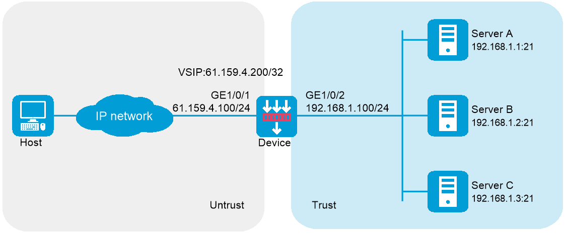
Software versions used
This configuration example was created and verified on R9900P2705 of the F5000-AI-55-G device.
Procedure
Assign IP addresses to interfaces and add the interfaces to security zones.
# On the top navigation bar, click
Network .# From the navigation pane, select
Interface Configuration >Interfaces .# Click the
Edit icon for GE 1/0/1.# In the dialog box that opens, configure the interface:
Select the
Unt rust security zone.On the
IPv4 Address tab, enter the IP address and mask length of the interface. In this example, enter 61.159.4.100/24.Use the default settings for other parameters.
Click
OK .
# Add GE 1/0/2 to the
T rust security zone and set its IP address to 192.168.1.100/24 in the same way you configure GE 1/0/1.Configure security policies.
# On the top navigation bar, click
Policies .# From the navigation pane, select
Security Policies >Security Policies .# Click
Create .# In the dialog box that opens, configure a security policy named
Untrust-to-Trust :Enter policy name
Untrust-to-Trust .Select type
IPv4 .Select source zone
Untrust .Select destination zone
Trust .Enter destination IPv4 address
61.159.4.0/24 .Select action
Permit .Use the default settings for other parameters.
Click
OK .
# Configure a security policy named
Local-to-Trust :Enter policy name
Local-to-Trust .Select type
IPv4 .Select source zone
Local .Select destination zone
Trust .Enter destination IPv4 address
192.168.1.0/24 .Select action
Permit .Use the default settings for other parameters.
Click
OK .
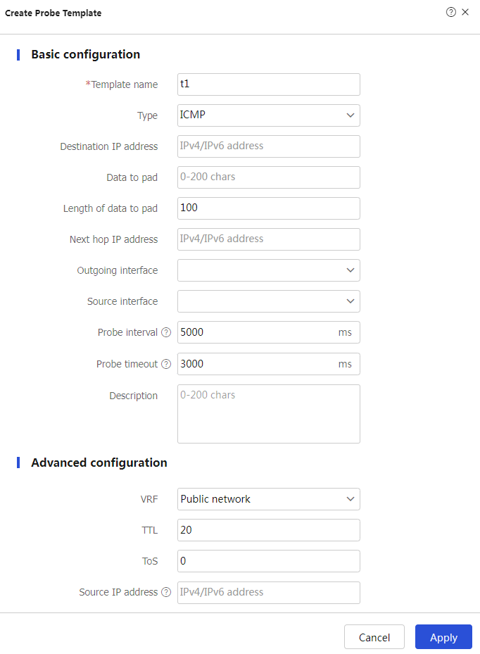
Create an ICMP-type probe template.
# On the top navigation bar, click
Objects .# From the navigation pane, select
Load Balancing >Health Monitoring .# Click
Create to configure the probe templatet1 as shown in Figure-2.Figure-2 Creating probe template t1
# Click
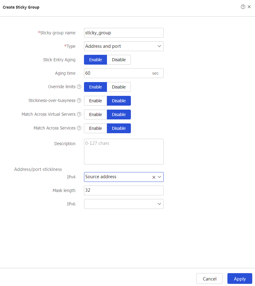
OK .Create an address- and port-type sticky group.
# On the top navigation bar, click
Objects .# From the navigation pane, select
Load Balancing >Sticky Groups .# Click
Create to configure the sticky groupsticky_group as shown in Figure-3.Figure-3 Creating sticky group sticky_group
# Click
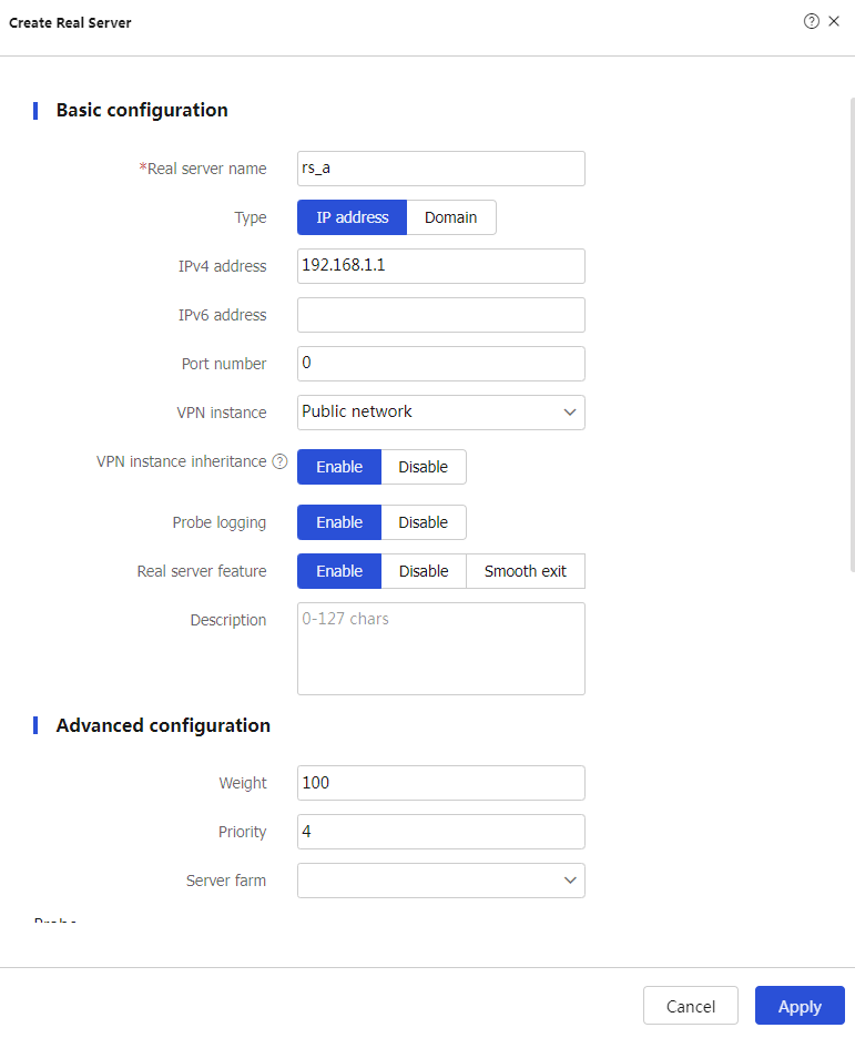
Apply .Create real servers.
# On the top navigation bar, click
Policies .# From the navigation pane, select
Load Balancing >Server Load Balancing >Real Servers .# Click
Create to configure the real serverrs_a as shown in Figure-4.Figure-4 Creating real server rs_a
# Click
Apply .# Configure real server
rs_b and set its IP address to 192.168.1.2 in the same way you configure real serverrs_a .# Configure real server
rs_ c and set its IP address to 192.168.1.3 in the same way you configure real serverrs_a .# Display the configured real servers as shown in Figure-5.
Figure-5 Displaying the configured real servers

Create server farms.
# On the top navigation bar, click
Policies .# From the navigation pane, select
Server Load Balancing >Server Farms .# Click
Create to configure the server farmsf1 as shown in Figure-6.Figure-6 Creating server farm sf1
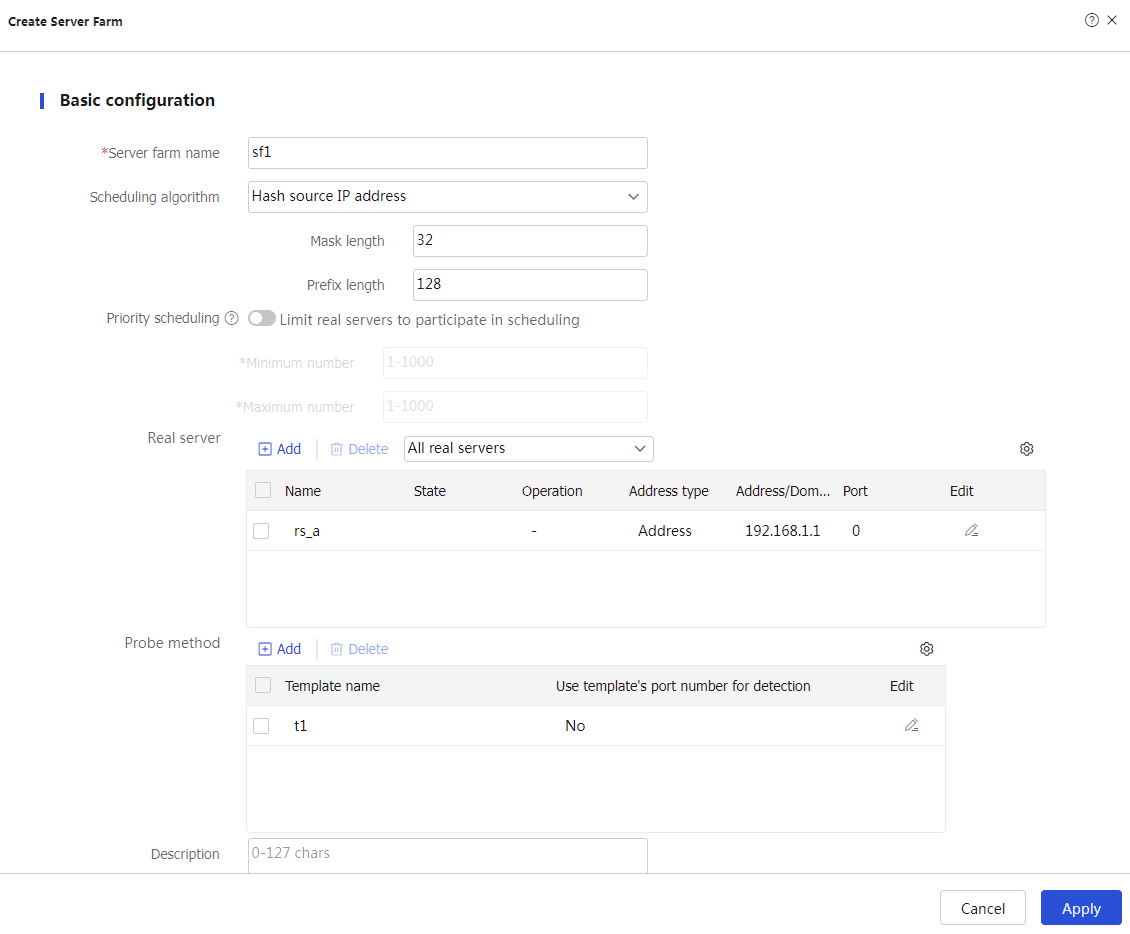
# Click
Apply .# Configure server farm
sf2 and specify real serverrs_b in the same way you configure server farmsf 1 .# Configure server farm
sf 3 and specify real serverrs_ c in the same way you configure server farmsf 1 .# Display the configured server farms as shown in Figure-7.
Figure-7 Displaying the configured server farms

Create classes.
# On the top navigation bar, click
Policies .# From the navigation pane, select
Load Balancing >Server Load Balancing >Advanced Policies .# Click the
Class tab.# Click
Create to configure the classcls_1 as shown in Figure-8.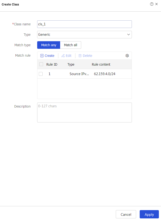
# Click
Apply .# Click
Create to configure the classcls_ 2 as shown in Figure-9.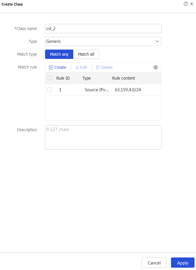
# Click
Apply .Create actions.
# On the top navigation bar, click
Policies .# From the navigation pane, select
Load Balancing >Server Load Balancing >Advanced Policies .# Click the
Action tab.# Click
Create to configure the actionact_1 as shown in Figure-10.Figure-10 Creating action act_1
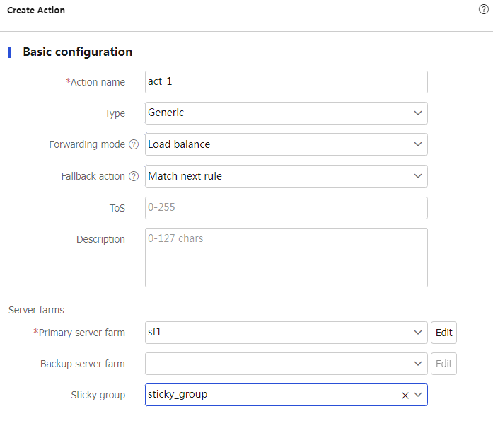
# Click
OK .# Configure action
act_2 and specify primary server farmsf2 in the same way you configure actionact_ 1 .# Configure action
act_ 3 and specify primary server farmsf 3 in the same way you configure actionact_ 1 .# Display the configured actions as shown in Figure-11.
Figure-11 Displaying the configured actions

Create a load balancing policy.
# On the top navigation bar, click
Policies .# From the navigation pane, select
Load Balancing >Server Load Balancing >Advanced Policies .# Click the
L o ad Balancing Policy tab.# Click
Create to configure the load balancing policyloadbalance_policy as shown in Figure-12.Figure-12 Creating load balancing policy loadbalance_policy

# Click
Apply .Create a virtual server.
# On the top navigation bar, click
Policies .# From the navigation pane, select
Load Balancing >Server Load Balancing >Virtual Servers .# Click
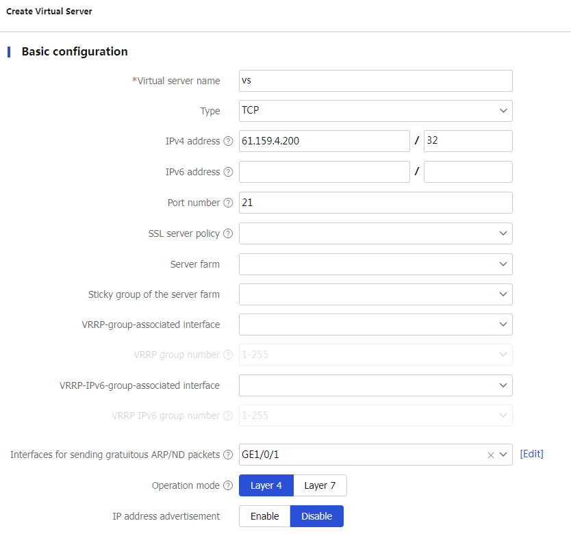
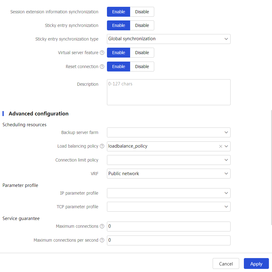
Create to configure the virtual serverv s as shown in Figure-13.Figure-13 Creating virtual server vs (basic configuration)
# Click
Apply .
Verifying the configuration
Verify that Device assigns Sever A the FTP requests sourced from host IP address 62.159.4.1 and destined to virtual server IP address 61.159.4.200.
# Access virtual server IP address 61.159.4.200 on the host with IP address 62.159.4.1.
C:\Users\system>ftp 61.159.4.200
Connected to 61.159.4.200. 220 FTP service ready.
User (61.159.4.200:(none)): admin331 Password required for admin.
Password: 230 User logged in.
ftp>
# On the top navigation bar, click
Monitor .# From the navigation pane, select
L B Monitor >Server LB Statistics >Virtual Servers .Figure-14 Displaying virtual server statistics

# On the top navigation bar, click
Monitor .# From the navigation pane, select
LB Monitor >Server LB Statistics >Servers Farms . You can see that Device assigns FTP requests sourced from 62.159.4.1 to server farmsf1 .Figure-15 Displaying server farm statistics

Verify that Device assigns Sever B the FTP requests sourced from host IP address 63.159.4.1 and destined to virtual server IP address 61.159.4.200.
Verify that Device assigns Sever C the FTP requests sourced from host IP address 64.159.4.1 and destined to virtual server IP address 61.159.4.200.