CLI example: Configuring basic Layer 7 server load balancing
Network configuration
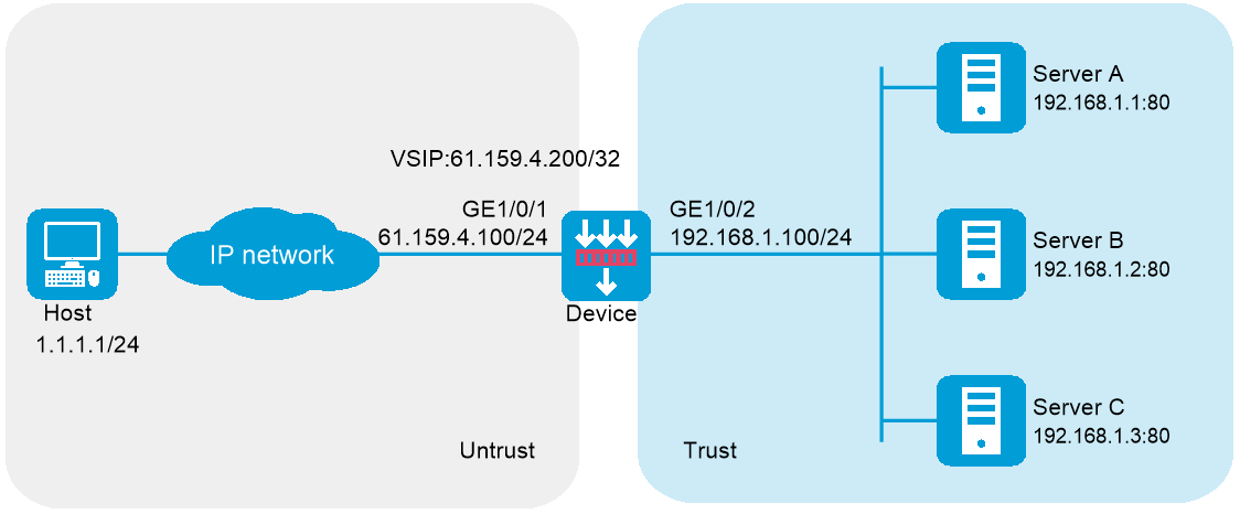
In Figure-1, physical servers Server A, Server B, and Server C provide HTTP services, and are in descending order of hardware configuration.
Configure server load balancing on the device to distribute user requests among the servers based on their hardware performance, and use health monitoring to monitor reachability of the servers.
Software versions used
This configuration example was created and verified on R9900P2705 of the F5000-AI-55-G device.
Procedure
Configure the device:
Assign IP addresses to interfaces:
# Assign an IP address to interface GigabitEthernet 1/0/1.
<Device> system-view
[Device] interface gigabitethernet 1/0/1
[Device-GigabitEthernet1/0/1] ip address 61.159.4.100 255.255.255.0
[Device-GigabitEthernet1/0/1] quit
# Assign IP addresses to other interfaces in the same way. (Details not shown.)
Configure settings for routing.
This example configures a static route, and the next hop in the route is 61.159.4.1.
[Device] ip route-static 1.1.1.1 24 61.159.4.1
Add interfaces to security zones.
[Device] security-zone name untrust
[Device-security-zone-Untrust] import interface gigabitethernet 1/0/1
[Device-security-zone-Untrust] quit
[Device] security-zone name trust
[Device-security-zone-Trust] import interface gigabitethernet 1/0/2
[Device-security-zone-Trust] quit
Configure a security policy:
Configure rules to permit traffic from the
Untrust security zone to theLocal security zone and traffic from theLocal security zone to theTrust security zone, so the users can access the servers:# Configure a rule named
lblocalin to allow the users to send packets to the device.[Device] security-policy ip
[Device-security-policy-ip] rule name lblocalin
[Device-security-policy-ip-1-lblocalin] source-zone untrust
[Device-security-policy-ip-1-lblocalin] destination-zone local
[Device-security-policy-ip-1-lblocalin] destination-ip-subnet 61.159.4.0 255.255.255.0
[Device-security-policy-ip-1-lblocalin] action pass
[Device-security-policy-ip-1-lblocalin] quit
# Configure a rule named
lblocalout to allow the device to send packets to the servers.[Device-security-policy-ip] rule name lblocalout
[Device-security-policy-ip-2-lblocalout] source-zone local
[Device-security-policy-ip-2-lblocalout] destination-zone trust
[Device-security-policy-ip-2-lblocalout] destination-ip-subnet 192.168.1.0 255.255.255.0
[Device-security-policy-ip-2-lblocalout] action pass
[Device-security-policy-ip-2-lblocalout] quit
[Device-security-policy-ip] quit
Configure a server farm.
# Create the HTTP-type NQA template
t1 .[Device] nqa template http t1
[Device-nqatplt-http-t1] quit
# Create server farm
sf , and specify the scheduling algorithm as weighted round robin and health monitoring method ast1 .[Device] server-farm sf
[Device-sfarm-sf] predictor round-robin
[Device-sfarm-sf] probe t1
[Device-sfarm-sf] quit
Configure real servers.
# Create the real server
rs1 with IPv4 address 192.168.1.1, port number 8080, and weight 150, and add it to the server farmsf .[Device] real-server rs1
[Device-rserver-rs1] ip address 192.168.1.1
[Device-rserver-rs1] port 8080
[Device-rserver-rs1] weight 150
[Device-rserver-rs1] server-farm sf
[Device-rserver-rs1] quit
# Create the real server
rs2 with IPv4 address 192.168.1.2, port number 8080, and weight 120, and add it to the server farmsf .[Device] real-server rs2
[Device-rserver-rs2] ip address 192.168.1.2
[Device-rserver-rs2] port 8080
[Device-rserver-rs2] weight 120
[Device-rserver-rs2] server-farm sf
[Device-rserver-rs2] quit
# Create the real server
rs3 with IPv4 address 192.168.1.3, port number 8080, and weight 80, and add it to the server farmsf .[Device] real-server rs3
[Device-rserver-rs3] ip address 192.168.1.3
[Device-rserver-rs3] port 8080
[Device-rserver-rs3] weight 80
[Device-rserver-rs3] server-farm sf
[Device-rserver-rs3] quit
Configure a virtual server.
# Create the HTTP virtual server
vs with VSIP 61.159.4.200, specify its default master server farmsf , and enable the virtual server.[Device] virtual-server vs type http
[Device-vs-http-vs] virtual ip address 61.159.4.200
[Device-vs-http-vs] default server-farm sf
[Device-vs-http-vs] service enable
# Specify an interface for sending gratuitous ARP packets and ND packets (if the interface IP address on the device and the VSIP belong to the same subnet).
[ Device-vs-http-vs] arp-nd interface gigabitethernet 1/0/1[Device-vs-http-vs] quit
Configure the physical servers:
# Specify the default gateway 192.168.1.100 for physical servers Server A, Server B, and Server C. (Details not shown.)
Verifying the configuration
# Display brief information about all real servers.
[Device] display real-server brief
Real server Address Port State VPN instance Server farm
rs1 192.168.1.1 8080 Active sf
rs2 192.168.1.2 8080 Active sf
rs3 192.168.1.3 8080 Active sf
# Display detailed information about all server farms.
[Device] display server-farm
Server farm: sf
Description:
Predictor: Round robin
Proximity: Disabled
NAT: Enabled
SNAT pool:
Failed action: Keep
Active threshold: Disabled
Slow-online: Disabled
Selected server: Disabled
Probe information:
Probe success criteria: All
Probe method:
t1
Total real server: 3
Active real server: 3
Real server list:
Name State VPN instance Address Port Weight Priority
rs1 Active 192.168.1.1 8080 150 4
rs2 Active 192.168.1.2 8080 120 4
rs3 Active 192.168.1.3 8080 80 4
# Display detailed information about all virtual servers.
[Device] display virtual-server
Virtual server: vs
Description:
Type: HTTP
State: Active
VPN instance:
Virtual IPv4 address: 61.159.4.200/32
Virtual IPv6 address: --
Port: 80
Primary server farm: sf (in use)
Backup server farm:
Sticky:
LB policy:
HTTP parameter profile:
Connection limit: --
Rate limit:
Connections: --
Bandwidth: --
Inbound bandwidth: --
Outbound bandwidth: --
SSL server policy:
SSL client policy:
Redirect relocation:
Redirect return-code: 302
Sticky synchronization: Disabled
Bandwidth busy protection: Disabled
Interface bandwidth statistics: Disabled
Route advertisement: Disabled
Configuration files
#
interface GigabitEthernet1/0/1
ip address 61.159.4.100 255.255.255.0
#
interface 33
ip address 192.168.1.100 255.255.255.0
#
security-zone name Untrust
import interface GigabitEthernet1/0/1
#
security-zone name Trust
import interface 33
#
security-policy ip
rule 1 name lblocalin
action pass
source-zone untrust
destination-zone local
source-ip-subnet 61.159.4.0 255.255.255.0
rule 2 name lblocalout
action pass
source-zone local
destination-zone trust
destination-ip-subnet 192.168.1.0 255.255.255.0
#
nqa template http t1
#
server-farm sf
probe t1
#
real-server rs1
ip address 192.168.1.1
port 21
weight 150
server-farm sf
#
real-server rs2
ip address 192.168.1.2
port 8080
weight 120
server-farm sf
#
real-server rs3
ip address 192.168.1.3
port 8080
weight 80
server-farm sf
#
virtual-server vs type http
virtual ip address 61.159.4.200
default server-farm sf
arp-nd interface GigabitEthernet1/0/1
service enable
#