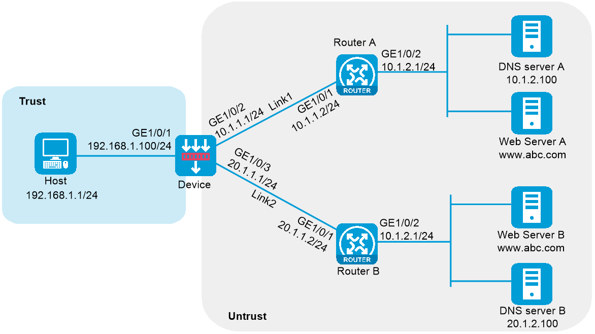
In Figure 1, ISP 1 and ISP 2 provide two links with the same bandwidth: Link 1 and Link 2. The IP address of the DNS server of ISP 1 is 10.1.2.100. The IP address of the DNS server of ISP 2 is 20.1.2.100. Intranet users use domain name www.example.com to access Web server A and Web server B.
Configure a transparent DNS proxy on the device to evenly distribute user traffic to Link 1 and Link 2.
This configuration example was created and verified on F9900 of the F5000-AI120 device.
1. Assign IP addresses to interfaces:
# Assign an IP address to interface GigabitEthernet 1/0/1.
<Device> system-view
[Device] interface gigabitethernet 1/0/1
[Device-GigabitEthernet1/0/1] ip address 192.168.1.100 255.255.255.0
[Device-GigabitEthernet1/0/1] quit
# Assign IP addresses to other interfaces in the same way. (Details not shown.)
2. Add interfaces to security zones.
[Device] security-zone name trust
[Device-security-zone-Trust] import interface gigabitethernet 1/0/1
[Device-security-zone-Trust] quit
[Device] security-zone name untrust
[Device-security-zone-Untrust] import interface gigabitethernet 1/0/2
[Device-security-zone-Untrust] import interface gigabitethernet 1/0/3
[Device-security-zone-Untrust] quit
3. Configure a security policy:
Configure rules to permit traffic from the Trust security zone to the Untrust security zone and traffic from the Local security zone to the Untrust security zone, so the users can access the server:
# Configure a rule named lbrule1 to allow the users to access the server.
[Device] security-policy ip
[Device-security-policy-ip] rule name lbrule1
[Device-security-policy-ip-1-lbrule1] source-zone trust
[Device-security-policy-ip-1-lbrule1] destination-zone untrust
[Device-security-policy-ip-1-lbrule1] source-ip-subnet 192.168.1.0 255.255.255.0
[Device-security-policy-ip-1-lbrule1] action pass
[Device-security-policy-ip-1-lbrule1] quit
# Configure a rule named lblocalout to allow the device to send probe packets to the next hop.
[Device-security-policy-ip] rule name lblocalout
[Device-security-policy-ip-2-lblocalout] source-zone local
[Device-security-policy-ip-2-lblocalout] destination-zone untrust
[Device-security-policy-ip-2-lblocalout] destination-ip-subnet 10.1.1.0 255.255.255.0
[Device-security-policy-ip-2-lblocalout] destination-ip-subnet 20.1.1.0 255.255.255.0
[Device-security-policy-ip-2-lblocalout] action pass
[Device-security-policy-ip-2-lblocalout] quit
[Device-security-policy-ip] quit
4. Configure links:
# Create the link link1 with next hop address 10.1.1.2.
[Device] loadbalance link link1
[Device-lb-link-link1] router ip 10.1.1.2
[Device-lb-link-link1] quit
# Create the link link2 with next hop address 20.1.1.2.
[Device] loadbalance link link2
[Device-lb-link-link2] router ip 20.1.1.2
[Device-lb-link-link2] quit
5. Create a DNS server pool named dsp.
[Device] loadbalance dns-server-pool dsp
[Device-lb-dspool-dsp] quit
6. Configure DNS servers:
# Create a DNS server named ds1, configure its IP address as 10.1.2.100, assign it to DNS server pool dsp, and associate it with link link1.
[Device] loadbalance dns-server ds1
[Device-lb-ds-ds1] ip address 10.1.2.100
[Device-lb-ds-ds1] dns-server-pool dsp
[Device-lb-ds-ds1] link link1
[Device-lb-ds-ds1] quit
# Create a DNS server named ds2, configure its IP address as 20.1.2.100, assign it to DNS server pool dsp, and associate it with link link2.
[Device] loadbalance dns-server ds2
[Device-lb-ds-ds2] ip address 20.1.2.100
[Device-lb-ds-ds2] dns-server-pool dsp
[Device-lb-ds-ds2] link link2
[Device-lb-ds-ds2] quit
7. Configure a transparent DNS proxy:
# Create a UDP transparent DNS proxy named dns-proxy1, configure its IP address as 0.0.0.0, specify DNS server pool dsp as its default DNS server pool, and enable the transparent DNS proxy.
[Device] loadbalance dns-proxy dns-proxy1 type udp
[Device-lb-dp-udp-dp] ip address 0.0.0.0 0
[Device-lb-dp-udp-dp] default dns-server-pool dsp
[Device-lb-dp-udp-dp] service enable
[Device-lb-dp-udp-dp] quit
# Display brief information about all DNS servers.
[Device] display loadbalance dns-server brief
DNS server Address Port Link State DNS server pool
ds1 10.1.2.100 0 link1 Active dsp
ds2 20.1.2.100 0 link2 Active dsp
# Display detailed information about all DNS server pools.
[Device] display loadbalance dns-server-pool
DNS server pool: dsp
Description:
Predictor: Round robin
Selected server: Disabled
Probe information:
Probe success criteria: All
Probe method:
Total DNS servers: 2
Active DNS servers: 2
DNS server list:
Name State Address port Link Weight Priority
ds1 Active 10.1.2.100 0 link1 100 4
ds2 Active 20.1.2.100 0 link2 100 4
# Display detailed information about all transparent DNS proxies.
[Device] display loadbalance dns-proxy
DNS proxy: dns-proxy1
Type: UDP
State: Active
Service state: Enabled
VPN instance:
IPv4 address: 1.1.1.0/24
IPv6 address: --
Port: 53
DNS server pool: dsp
Sticky:
LB policy:
Connection synchronization: Enabled
Sticky synchronization: Enabled
Bandwidth busy protection: Disabled
After you complete the previous configuration, the LB device can evenly distribute DNS requests to DNS server A and DNS server B. Then, intranet user traffic is evenly distributed to Link 1 and Link 2.
#
interface GigabitEthernet1/0/1
ip address 192.168.1.100 255.255.255.0
#
interface GigabitEthernet1/0/2
ip address 10.1.1.1 255.255.255.0
#
interface GigabitEthernet1/0/3
ip address 20.1.1.1 255.255.255.0
#
security-zone name Trust
import interface GigabitEthernet1/0/1
#
security-zone name Untrust
import interface GigabitEthernet1/0/2
import interface GigabitEthernet1/0/3
#
security-policy ip
rule 1 name lbrule1
action pass
source-zone trust
destination-zone untrust
source-ip-subnet 192.168.1.0 255.255.255.0
rule 2 name lblocalout
action pass
source-zone local
destination-zone untrust
destination-ip-subnet 10.1.1.0 255.255.255.0
destination-ip-subnet 20.1.1.0 255.255.255.0
#
loadbalance link link1
router ip 10.1.1.2
#
loadbalance link link2
router ip 20.1.1.2
#
loadbalance dns-server-pool dsp
#
loadbalance dns-server ds1
dns-server-pool dsp
ip address 10.1.2.100
link link1
#
loadbalance dns-server ds2
dns-server-pool dsp
ip address 20.1.2.100
link link2
#
loadbalance dns-proxy dns-proxy1 type udp
ip address 0.0.0.0 0
service enable
default dns-server-pool dsp