This configuration example was created and verified on F9900 of the F5000-AI120 device.
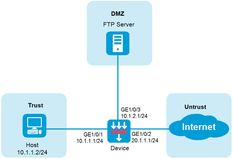
As shown in Figure 1, the device acts as a security gateway deployed at the edge of the internal network. Configure packet capture as follows:
Capture bidirectional packets on GigabitEthernet 1/0/1 between the 10.1.1.0/24 network and the 20.1.1.0/24 network.
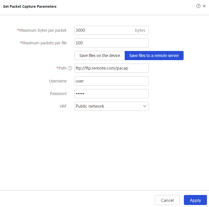
Set the maximum packet size for a packet capture record to 3000 bytes.
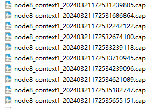
Use an FTP server to save the .cap files.
Assign IP addresses to interfaces:
# On the top navigation bar, click Network. From the navigation pane, select Interface Configuration > Interfaces.
# Click the Edit icon for GE 1/ 0/1. In the dialog box that opens, configure the interface.
Select the Trust security zone.
Enter the IP address/mask 10.1.1.1/ 24.
Use the default settings for other parameters.
# Click OK.
# Configure GE 1/0/2 in the same way as GE 1/0/1 was configured.
Select the Untrust security zone.
Enter the IP address/mask 20.1.1.1/ 24.
Use the default settings for other parameters.
# Click OK.
# Configure GE 1/0/3 in the same way as GE 1/0/1 was configured.
Select the DMZ security zone.
Enter the IP address/mask 10.1.2.1/ 24.
Use the default settings for other parameters.
# Click OK.
Create a security policy to allow the host to access the Internet:
# On the top navigation bar, click Policies. From the navigation pane, select Security Policies > Security Policies.
# Click Create. The configuration is as follows.
Enter security policy name untrust-trust.
Select Trust as the source security zone.
Select Untrust as the destination security zone.
Set the type to IPv4.
Set the action to Permit.
Use the default settings for other parameters.
# Click OK.
Create a security policy to allow captured packets to reach the FTP server:
# On the top navigation bar, click Policies. From the navigation pane, select Security Policies > Security Policies.
# Click Create, and select Create policy.
Enter policy name capturelocalout.
Select local as the source security zone.
Select DMZ as the destination security zone.
Set the type to IPv4.
Set the action to Permit.
Enter destination IPv4 address 10.1.2.2.
Use the default settings for other parameters.
# Click OK.
Create IPv4 advanced ACL 3000, and configure rules to match packets with the source IP address on the 10.1.1.0/24 network and packets with the source IP address on the 20.1.1.0/24 network:
|
|
You do not need to configure specify a VRF for an ACL in either a VRF or a non-VRF scenario. |
# On the top navigation bar, click Objects. From the navigation pane, select ACLs > IPv4.
# Click Create.
Figure 2 Configuring an IPv4 ACL

Click OK & Add Rule. Configure rule 0 to match packets with the source IP address on the 10.1.1.0/24 network. The configuration is as follows:
Figure 3 Creating rule 0

# Use the default settings for other parameters.
Click OK & Add More. Configure rule 1 to match packets with the source IP address on the 20.1.1.0/24 network. The configuration is as follows:
Figure 4 Creating rule 1
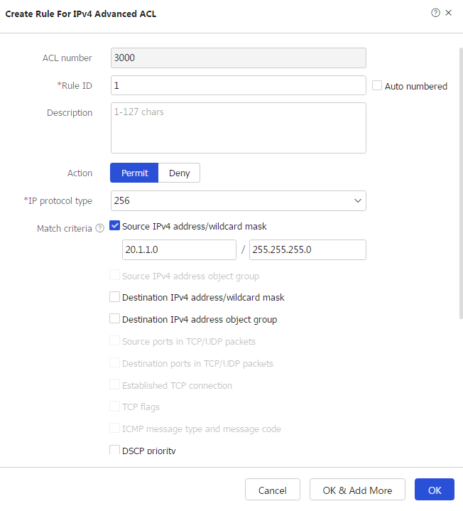
# Use the default settings for other parameters.
# Click OK.
Configure packet capture:
# On the top navigation bar, click MonitorSystem. From the navigation pane, select Diagnosis Center > Packet Capture. Click Set packet capture parameters.
Figure 5 Configuring packet capture parameters
# Click OK.
Click Start packet capture to configure packet capture filters.
Figure 6 Configuring packet capture filters
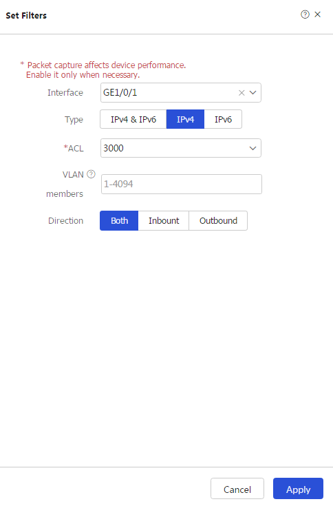
# Click OK.
Verify that the device can send captured packets to the FTP server.