This configuration example was created and verified on F9900 of the F5000-AI120 device.
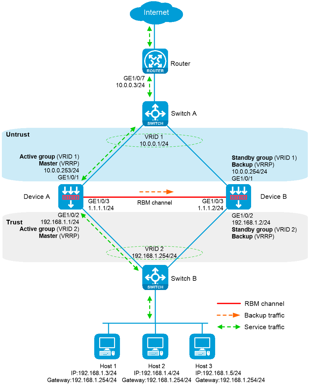
As shown in Figure 1, physical servers Server A, Server B, and Server C provide FTP services, and are in descending order of hardware configuration.
Configure server load balancing on the device to distribute user requests among the servers based on their hardware performance, and use health monitoring to monitor the reachability of the servers.
For high availability purposes, implement hot backup for Device A and Device B. Device A acts as the primary device and Device B acts as the secondary device. When Device A or its link fails, Device B takes over to ensure service continuity.
Before you set up an HA system, verify that the hardware and software settings are consistent on the candidate member devices.
This example uses the Ethernet interface as both the control channel and data channel interface. If a device has both HA and Ethernet interfaces, use the HA interface for these purposes to enhance security and stability. The HA interface should not serve as a service interface.
Before you set up an HA system, verify that the following hardware settings are consistent on the candidate member devices:
Device model.
Number and type of management interfaces on the active and standby devices, service interfaces, and interfaces for setting up the control channels and data channels. Do not use one interface for multiple purposes.
Type, location, and number of disks. A device without disks installed has small log storage and does not support some types of logs or reports.
Before you set up an HA system, verify that the following software settings are consistent on the candidate member devices:
Software environment and version, including boot packages, system packages, feature packages, and patches.
Licensed signature libraries and features, such as signature library types, signature library version, validation time, and number of licensed resources.
Interface numbers.
Type, speed, and number of the interfaces for setting up the HA control channels and data channels. As a best practice, use aggregate interfaces.
Aggregate interface numbers and aggregation member port numbers.
Security zones for the interfaces with the same numbers.
To delete or edit configurations related to load balancing services if these configurations can be backed up, perform these operations only on the primary device. To avoid configuration inconsistency, do not perform these operations on the secondary device.
Configure NQA templates on both the primary and secondary devices, and make sure the configurations are consistent. Import, deploy, and save files, including the ISP files related to load balancing, certificate files for SSL offloading, and script files for custom monitoring, separately on the primary and secondary devices.
On Switch A, create VLAN 10, configure all interfaces to operate in Layer 2 mode, configure the link type as access for all the interfaces, and assign the interfaces to VLAN 10.
On Switch A, create VLAN 10, configure all interfaces to operate in Layer 2 mode, configure the link type as access for all the interfaces, and assign the interfaces to VLAN 10.
# Assign IPv4 address 10.0.0.3/24 to interface GigabitEthernet 1/0/7.
# Configure a route to 10.0.0.1, which is the virtual IPv4 address of VRRP group 1, for inbound traffic and a route to the IPv4 address of the peer interface of the output interface for traffic to the Internet.
Assign IP addresses to interfaces:
# On the top navigation bar, click Network.
# From the navigation pane, select Interface Configuration > Interfaces.
# Click the Edit icon for GE 1/0/1. In the dialog box that opens, configure the interface.
Select the Untrust security zone.
On the IPv4 Address tab, enter the IP address and mask of the interface. In this example, enter 10.0.0.253/24.
Use the default settings for other parameters.
# Click OK.
# Configure interface GE 1/0/2 in the same way as interface GE 1/0/1 is configured.
Select security zone Trust.
On the IPv4 Address tab, enter the IP address and mask of the interface. In this example, enter 192.168.1.1/24.
Use the default settings for other parameters.
# Configure interface GE 1/0/3 in the same way as interface GE 1/0/1 is configured.
On the IPv4 Address tab, enter the IP address and mask of the interface. In this example, enter 1.1.1.1/24.
Use the default settings for other parameters.
Configure the route:
This section takes static routing as an example. If you need dynamic routing in your network, configure the corresponding dynamic routing protocol as needed.
# On the top navigation bar, click Network.
# From the navigation pane, select Routing > Static Routing.
# On the IPv4 Static Routing tab, click Create.
# In the dialog box that opens, configure an IPv4 static route as follows:
Set the destination IP address to 0.0.0.0.
Set the mask length to 0.
Enter next hop address 10.0.0.3.
Use the default settings for other parameters.
# Click OK.
Configure the security policy to permit service packets as needed.
Configure the security policy only on the primary device. After you complete the HA networking, the secondary device automatically synchronize the security policy configuration.
# On the top navigation bar, click Policies.
# From the navigation pane, select Security Policies > Security Policies.
# Click Create.
# In the dialog box that opens, create a security policy and configure it as follows:
Enter security policy name trust-untrust.
Select source security zone Trust.
Select destination security zone Untrust.
Set the type to IPv4.
Set the action to Permit.
Set the source IPv4 address to 192.168.1.0/24.
Use the default settings for other parameters.
# Click OK.
Configure security policies to permit VRRP packets to pass.
When the HA channel is disconnected, these policies enable Device A and Device B to exchange VRRP packets for VRRP role election, ensuring network communication.
Configure the security policy only on the primary device. After you complete the HA networking, the secondary device automatically synchronize the security policy configuration.
# On the top navigation bar, click Policies.
# From the navigation pane, select Security Policies > Security Policies.
# Click Create.
# In the dialog box that opens, create a security policy and configure it as follows:
Enter policy name vrrp1.
Select source security zone Trust.
Select destination security zone Local.
Set the type to IPv4.
Set the action to Permit.
Select service object group vrrp.
Use the default settings for other parameters.
# Click OK.
# In the dialog box that opens, create a security policy and configure it as follows:
Enter policy name vrrp2.
Select source security zone Local.
Select destination security zone Trust.
Set the type to IPv4.
Set the action to Permit.
Select service object group vrrp.
Use the default settings for other parameters.
# Click OK.
# In the dialog box that opens, create a security policy and configure it as follows:
Enter policy name vrrp3.
Select source security zone Untrust.
Select destination security zone Local.
Set the type to IPv4.
Set the action to Permit.
Select service object group vrrp.
Use the default settings for other parameters.
# Click OK.
# In the dialog box that opens, create a security policy and configure it as follows:
Enter policy name vrrp4.
Select source security zone Local.
Select destination security zone Untrust.
Set the type to IPv4.
Set the action to Permit.
Select service object group vrrp.
Use the default settings for other parameters.
# Click OK.
# On the top navigation bar, click System.
# From the navigation pane, select High Availability > HA Group.
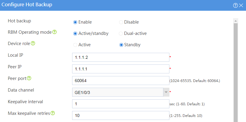
# Click Configure.
Figure 2 Configuring hot backup
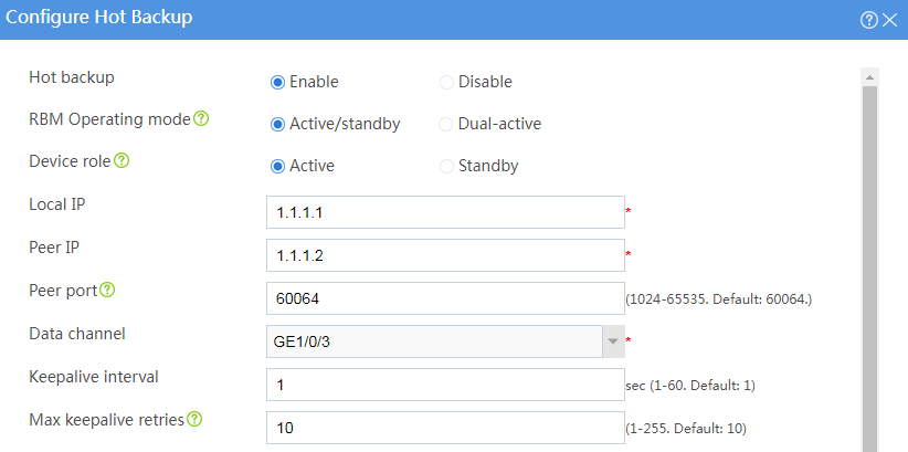
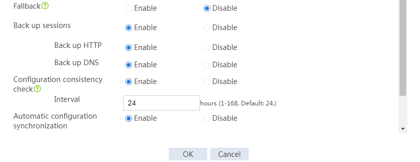
# Click OK.
# On the top navigation bar, click System.
# From the navigation pane, select High Availability > VRRP.
# Click Create.
Figure 3 Configuring VRRP group 1
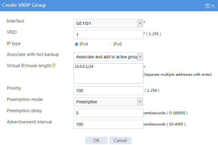
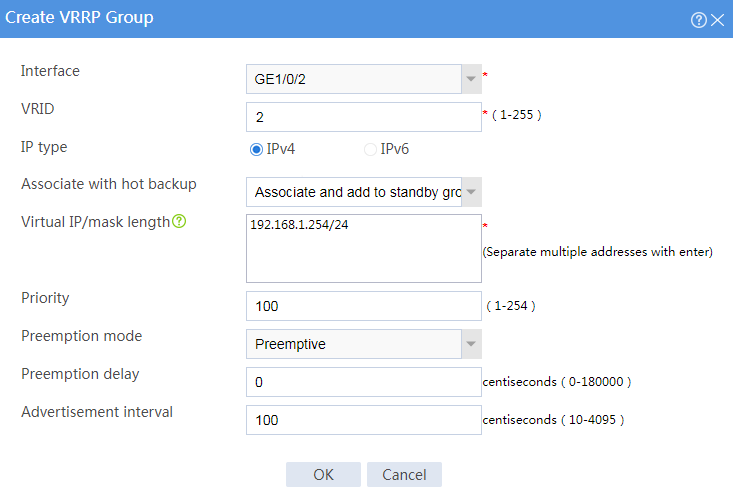
Figure 4 Configuring VRRP group 2

# Click OK.
# On the top navigation bar, click Objects.
# From the navigation pane, select Load Balancing > Health Monitoring.
# Click Create.
Figure 5 Creating a probe template
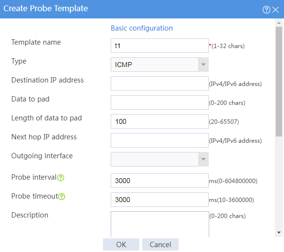
# Click OK.
Perform the following steps only on the primary device (Device A). The secondary device automatically synchronizes these load balancing configurations from the primary device.
Configure a source address pool
# On the top navigation bar, click Objects.
# From the navigation pane, select Load Balancing > SNAT Pools.
# Click Create.
Figure 6 Creating an SNAT pool
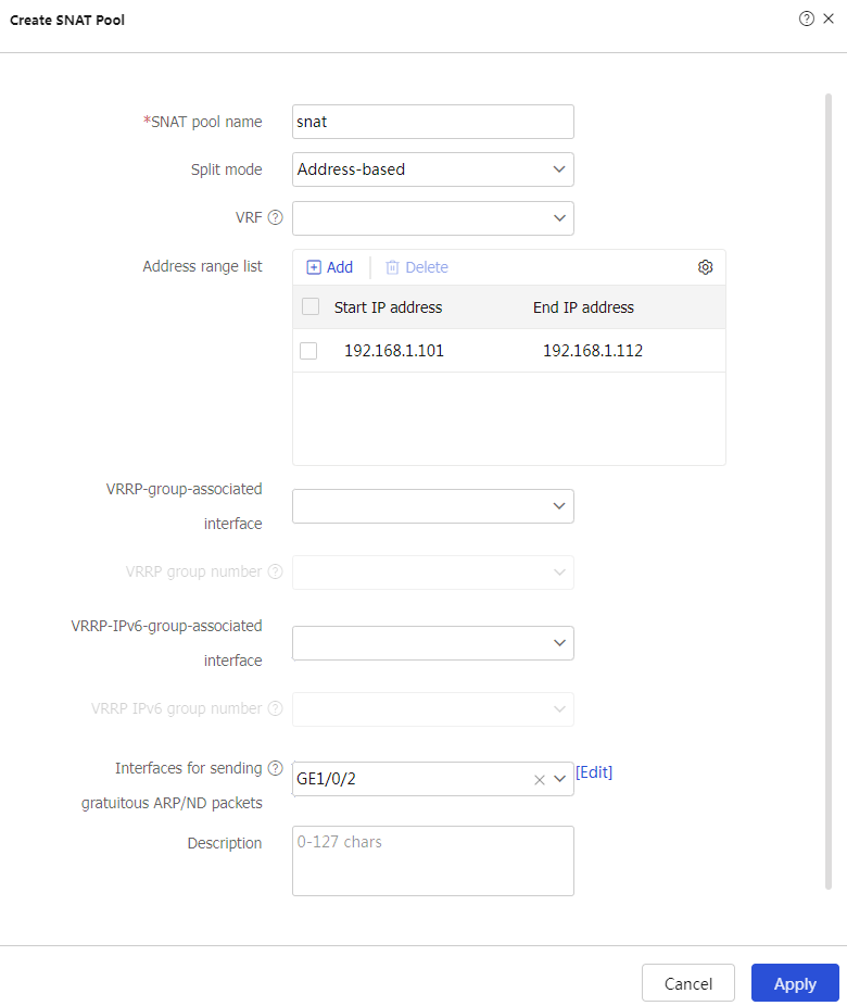
# Click Apply.
# On the top navigation bar, click Policies.
# From the navigation pane, select Load Balancing > Server Load Balancing > Real Servers.
# Click Create.
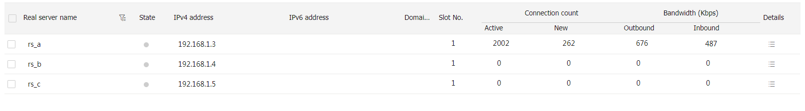
Figure 7 Configuring real server rs_a
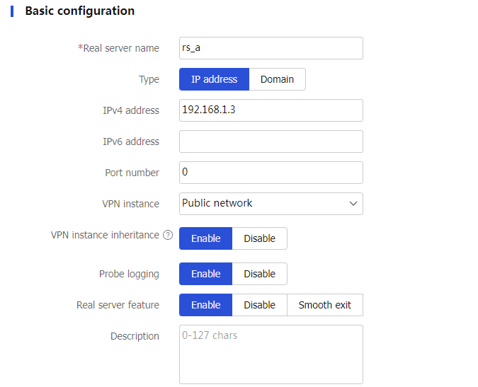
# Click OK.
Configure real server rs_b in the same way as real server rs_a is configured, with the IPv4 address set to 192.168.1.4.
Configure real server rs_c in the same way as real server rs_a is configured, with the IPv4 address set to 192.168.1.5.
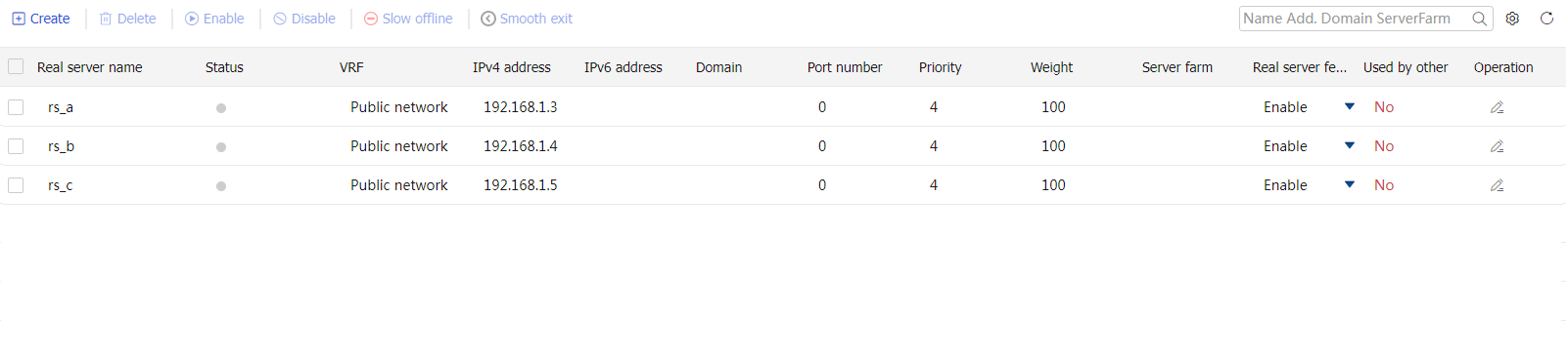
After configuration, the following information is displayed.
Figure 8 Real servers
# On the top navigation bar, click Policies.
# From the navigation pane, select Load Balancing > Server Load Balancing > Server Farms.
Figure 9 Configuring the server farm
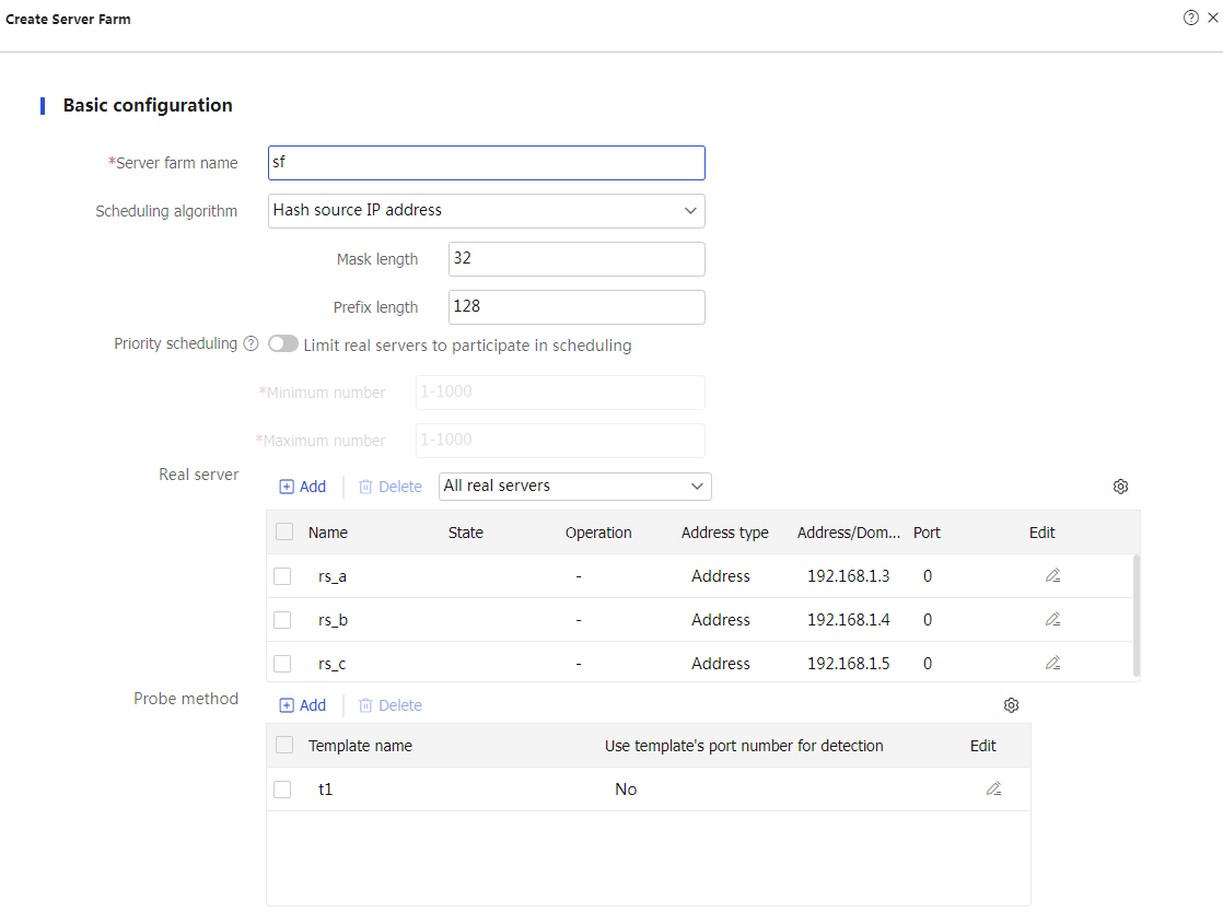
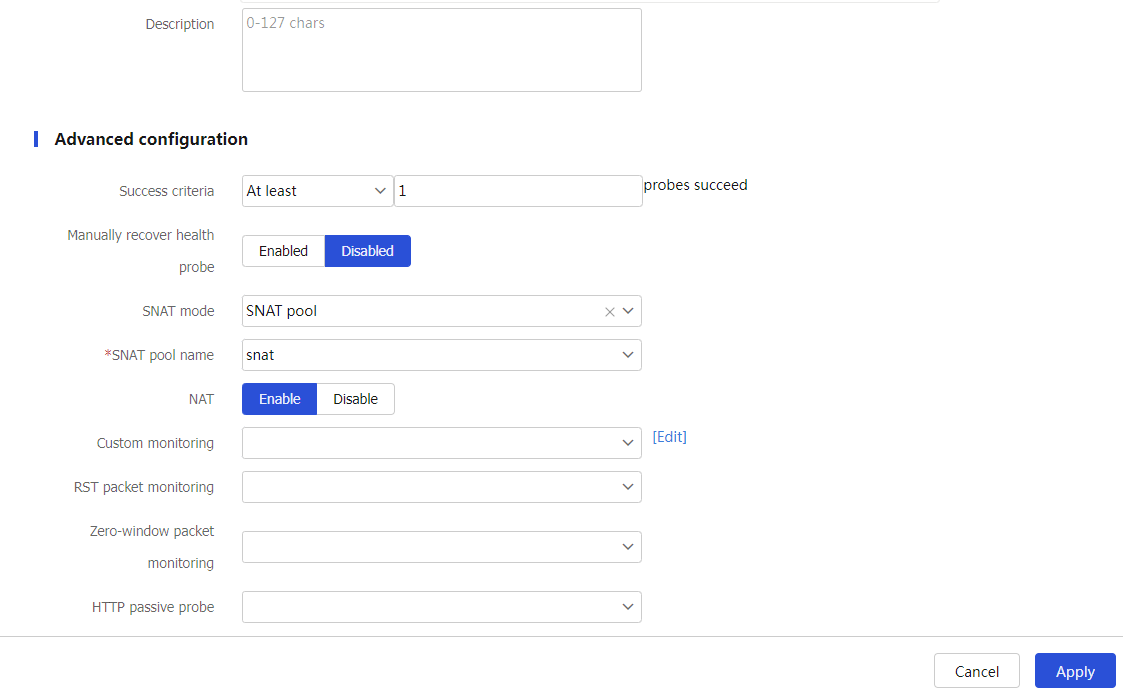
# Click Create.
# On the top navigation bar, click Policies.
# From the navigation pane, select Load Balancing > Server Load Balancing > Virtual Servers.
# Click Create.
Figure 10 Configuring virtual server vs
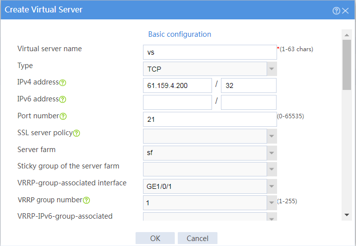
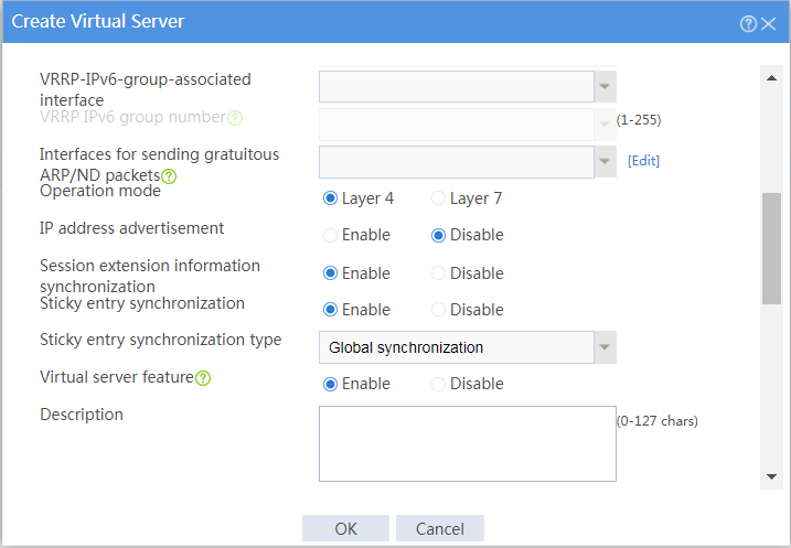
# Click OK.
Assign IP addresses to interfaces:
# On the top navigation bar, click Network.
# From the navigation pane, select Interface Configuration > Interfaces.
# Click the Edit icon for GE 1/0/1. In the dialog box that opens, configure the interface.
Select the Untrust security zone.
On the IPv4 Address tab, enter the IP address and mask of the interface. In this example, enter 10.0.0.254/24.
Use the default settings for other parameters.
# Click OK.
# Configure interface GE 1/0/2 in the same way as interface GE 1/0/1 is configured.
Select security zone Trust.
On the IPv4 Address tab, enter the IP address and mask of the interface. In this example, enter 192.168.1.2/24.
Use the default settings for other parameters.
# Configure interface GE 1/0/3 in the same way as interface GE 1/0/1 is configured.
On the IPv4 Address tab, enter the IP address and mask of the interface. In this example, enter 1.1.1.1/24.
Use the default settings for other parameters.
Configure the route:
This section takes static routing as an example. If you need dynamic routing in your network, configure the corresponding dynamic routing protocol as needed.
# On the top navigation bar, click Network.
# From the navigation pane, select Routing > Static Routing.
# On the IPv4 Static Routing tab, click Create.
# In the dialog box that opens, configure an IPv4 static route as follows:
Set the destination IP address to 0.0.0.0.
Set the mask length to 0.
Enter next hop address 10.0.0.3.
Use the default settings for other parameters.
# Click OK.
# On the top navigation bar, click System.
# From the navigation pane, select High Availability > HA Group.
# Click Configure.
Figure 11 Configuring hot backup

# Click OK.
# On the top navigation bar, click System.
# From the navigation pane, select High Availability > VRRP.
# Click Create.
Figure 12 Configuring VRRP group 1
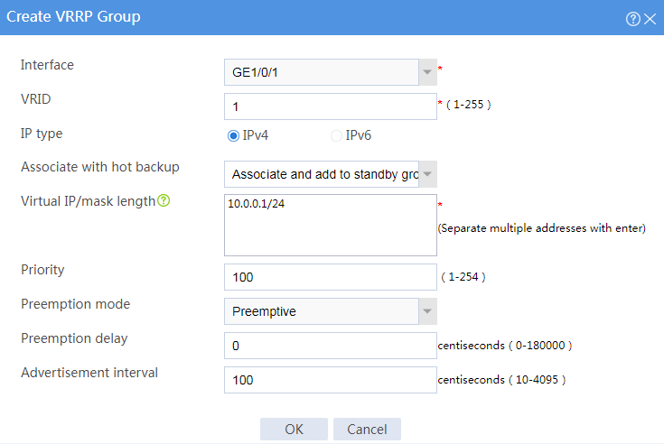
Figure 13 Configuring VRRP group 2
# Click OK.
# On the top navigation bar, click Objects.
# From the navigation pane, select Load Balancing > Health Monitoring.
# Click Create.
Figure 14 Creating a probe template

# Click OK.
# Configure 192.168.1.254, the virtual IPv4 address of VRRP group 2, as the default gateway for the host.
# When the primary device operates correctly, use a client with IP address 62.159.4.1 to initiate an FTP request to virtual server IP address 61.159.4.200.
C:\Users\system>ftp 61.159.4.200
Connected to 61.159.4.200
220 FTP service ready.
User(61.159.4.200:(none)): admin
331 Password required for admin.
Password:
230 User logged in.
ftp>
# Log in to the primary and secondary devices. On the top navigation bar, click Monitor. From the navigation pane, select LB Monitor > Server LB Statistics > Virtual Servers. Statistics on the primary device include the new connection count and active connection count. Statistics on the secondary device display only the active connection count.
Figure 15 Virtual server statistics on the primary device

Figure 16 Virtual server statistics on the secondary device

# Log in to the primary device. On the top navigation bar, click Monitor. From the navigation pane, select LB Monitor > Server LB Statistics > Real Servers. Statistics show that Device A has distributed traffic from the client with IP address 62.159.4.1 to real server rs1.
Figure 17 Real server statistics
# When the primary device fails, use a client with IP address 62.159.4.1 to initiate an FTP request to virtual server IP address 61.159.4.200.
C:\Users\system>ftp 61.159.4.200
Connected to 61.159.4.200
220 FTP service ready.
User(61.159.4.200:(none)): admin
331 Password required for admin.
Password:
230 User logged in.
ftp>
# Log in to the primary and secondary devices. On the top navigation bar, click Monitor. From the navigation pane, select LB Monitor > Server LB Statistics > Virtual Servers. Statistics on the primary device include only the new connection count. Statistics on the secondary device display the new connection count and active connection count.
Figure 18 Virtual server statistics on the primary device

Figure 19 Virtual server statistics on the secondary device

# Log in to the primary device. On the top navigation bar, click Monitor. From the navigation pane, select LB Monitor > Server LB Statistics > Real Servers. Statistics show that Device B has distributed traffic from the client with IP address 62.159.4.1 to real server rs1.
Figure 20 Real server statistics
