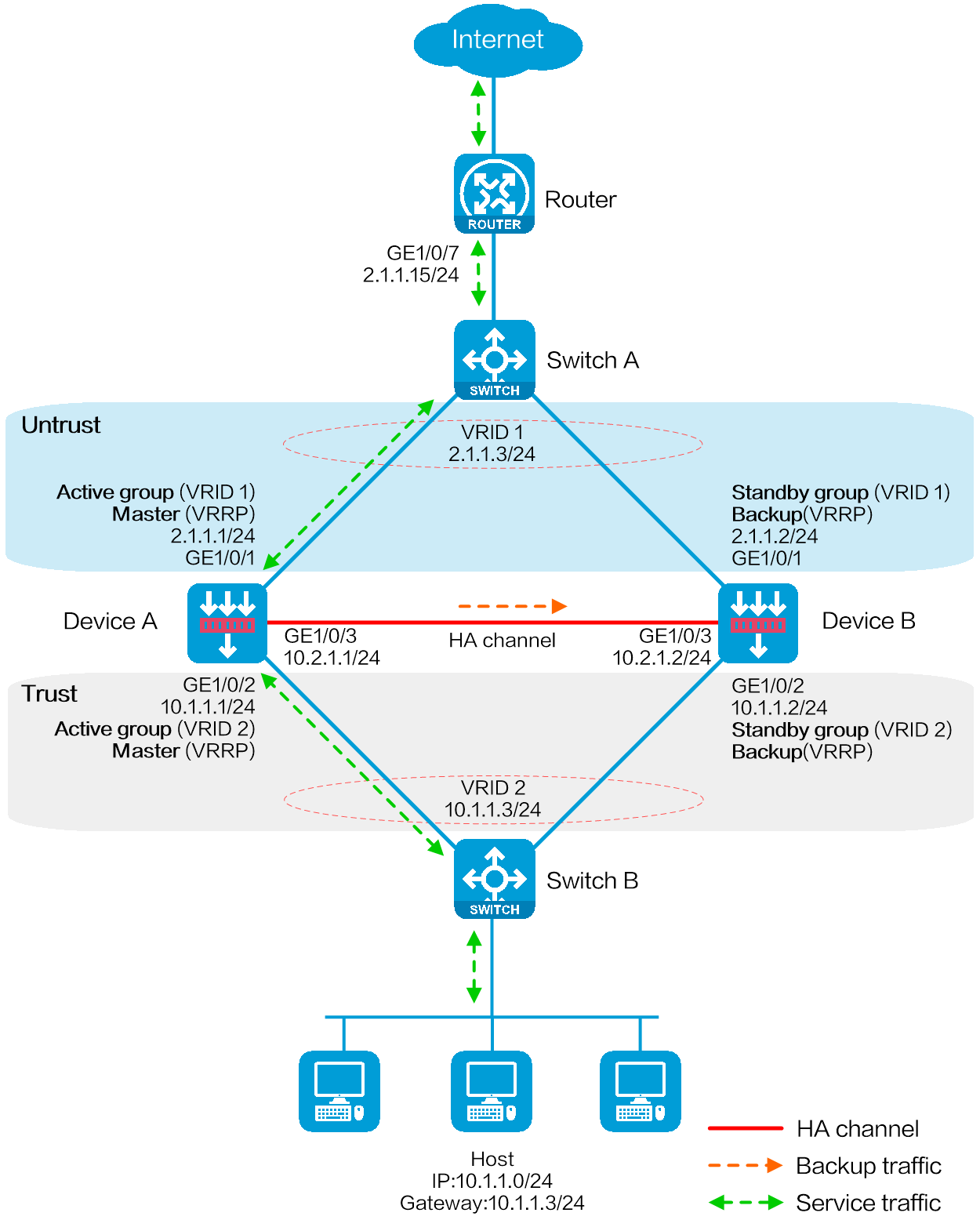
As shown in Figure 1, set up the HA group at the border between the Internet and the internal network of an enterprise to ensure service continuity.
Configure the HA group to collaborate with VRRP.
Configure the HA group to operate in active/standby mode.
Configure Device A and Device B as the primary device and the secondary device, respectively.
Configure dynamic NAT to translate the private IP addresses in the internal network into public IP addresses 2.1.1.1 through 2.1.1.10.
This configuration example was created and verified on F9900 of the F5000-AI120 device.
Before you configure hot backup, verify that the following hardware settings are the same on the devices to be assigned to a hot backup system:
Device model.
Number and type of management interfaces, service interfaces, and interfaces for setting up the hot backup channels. Do not use one interface for multiple purposes.
Location, number, and type of disks. A device not with disks installed has small log storage and do not support some types of logs or reports.
Before you configure hot backup, verify that the following software settings are the same on the devices to be assigned to a hot backup system:
Software environment and version, including boot packages, system packages, feature packages, and patches.
Licensed signature libraries and features, such as signature library types, signature library version, validation time, and number of licensed resources.
Interface numbers.
Type, speed, and number of the interfaces for setting up the hot backup channels. As a best practice, use aggregate interfaces.
Aggregate interface numbers and aggregation member port numbers.
Security zone configuration on the interfaces at the same location.
Multi-CPU packet distribution policy (configurable with the forwarding policy command).
Configure IPv4 addresses for interfaces.
# Assign an IPv4 address to GigabitEthernet 1/0/7.
<Router> system-view
[Router] interface gigabitethernet 1/0/7
[Router-GigabitEthernet1/0/7] ip address 2.1.1.15 255.255.255.0
[Router-GigabitEthernet1/0/7] quit
# Assign IP addresses to other interfaces in the same way. (Details not shown.)
Configure routes as follows:
# Specify 2.1.1.3 (virtual IP address of VRRP group 1) as the next hop of the routes to the subnets of the internal network.
# Specify 3.1.1.15 as the next hop of the route to the Internet.
[Router] ip route-static 10.1.1.0 255.255.255.0 2.1.1.3
[Router] ip route-static 0.0.0.0 0.0.0.0 3.1.1.15
Create VLAN 10 on Switch A, and configure the interfaces that connect Switch A to Device A, Device B, and Router as access ports, and then assign the ports to VLAN 10.
<SwitchA> system-view
[SwitchA] vlan 10
[SwitchA-vlan10] quit
[SwitchA] interface gigabitethernet 1/0/1
[SwitchA-GigabitEthernet1/0/1] port access vlan 10
[SwitchA-GigabitEthernet1/0/1] quit
[SwitchA] interface gigabitethernet 1/0/2
[SwitchA-GigabitEthernet1/0/2] port access vlan 10
[SwitchA-GigabitEthernet1/0/2] quit
[SwitchA] interface gigabitethernet 1/0/3
[SwitchA-GigabitEthernet1/0/3] port access vlan 10
[SwitchA-GigabitEthernet1/0/3] quit
Create VLAN 10 on Switch B, and configure the interfaces that connect Switch B to Device A, Device B, and Host as access ports, and then assign the ports to VLAN 10.
<SwitchB> system-view
[SwitchB] vlan 10
[SwitchB-vlan10] quit
[SwitchB] interface gigabitethernet 1/0/1
[SwitchB-GigabitEthernet1/0/1] port access vlan 10
[SwitchB-GigabitEthernet1/0/1] quit
[SwitchB] interface gigabitethernet 1/0/2
[SwitchB-GigabitEthernet1/0/2] port access vlan 10
[SwitchB-GigabitEthernet1/0/2] quit
[SwitchB] interface gigabitethernet 1/0/3
[SwitchB-GigabitEthernet1/0/3] port access vlan 10
[SwitchB-GigabitEthernet1/0/3] quit
Configure IPv4 addresses for interfaces.
# Assign an IPv4 address to GigabitEthernet 1/0/1.
<DeviceA> system-view
[DeviceA] interface gigabitethernet 1/0/1
[DeviceA-GigabitEthernet1/0/1] ip address 2.1.1.1 255.255.255.0
[DeviceA-GigabitEthernet1/0/1] quit
# Assign IP addresses to other interfaces in the same way. (Details not shown.)
Add interfaces to security zones.
[DeviceA] security-zone name untrust
[DeviceA-security-zone-Untrust] import interface gigabitethernet 1/0/1
[DeviceA-security-zone-Untrust] quit
[DeviceA] security-zone name trust
[DeviceA-security-zone-Trust] import interface gigabitethernet 1/0/2
[DeviceA-security-zone-Trust] quit
Configure settings for routing. This example configures a static route, and the next hop in the route is 2.1.1.15.
[DeviceA] ip route-static 0.0.0.0 0.0.0.0 2.1.1.15
Configure a security policy.
Perform this task only on the primary device. After the HA group is set up, the secondary device automatically synchronizes its security policy configuration with the primary device.
# Configure a rule named trust-untrust to permit the packets from 10.1.1.0/24 to the Internet.
[DeviceA] security-policy ip
[DeviceA-security-policy-ip] rule name trust-untrust
[DeviceA-security-policy-ip-0-trust-untrust] source-zone trust
[DeviceA-security-policy-ip-0-trust-untrust] destination-zone untrust
[DeviceA-security-policy-ip-0-trust-untrust] source-ip-subnet 10.1.1.0 24
[DeviceA-security-policy-ip-0-trust-untrust] action pass
[DeviceA-security-policy-ip-0-trust-untrust] quit
# Configure rules to permit VRRP protocol packets. When the HA channel is disconnected, Device A and Device B can exchange VRRP protocol packets to elect a VRRP master.
[DeviceA-security-policy-ip] rule name vrrp1
[DeviceA-security-policy-ip-1-vrrp1] source-zone trust
[DeviceA-security-policy-ip-1-vrrp1] destination-zone local
[DeviceA-security-policy-ip-1-vrrp1] service vrrp
[DeviceA-security-policy-ip-1-vrrp1] action pass
[DeviceA-security-policy-ip-1-vrrp1] quit
[DeviceA-security-policy-ip] rule name vrrp2
[DeviceA-security-policy-ip-2-vrrp2] source-zone local
[DeviceA-security-policy-ip-2-vrrp2] destination-zone trust
[DeviceA-security-policy-ip-2-vrrp2] service vrrp
[DeviceA-security-policy-ip-2-vrrp2] action pass
[DeviceA-security-policy-ip-2-vrrp2] quit
[DeviceA-security-policy-ip] rule name vrrp3
[DeviceA-security-policy-ip-3-vrrp3] source-zone untrust
[DeviceA-security-policy-ip-3-vrrp3] destination-zone local
[DeviceA-security-policy-ip-3-vrrp3] service vrrp
[DeviceA-security-policy-ip-3-vrrp3] action pass
[DeviceA-security-policy-ip-3-vrrp3] quit
[DeviceA-security-policy-ip] rule name vrrp4
[DeviceA-security-policy-ip-4-vrrp4] source-zone local
[DeviceA-security-policy-ip-4-vrrp4] destination-zone untrust
[DeviceA-security-policy-ip-4-vrrp4] service vrrp
[DeviceA-security-policy-ip-4-vrrp4] action pass
[DeviceA-security-policy-ip-4-vrrp4] quit
[DeviceA-security-policy-ip] quit
Configure HA group settings.
# Set up an HA group.
[DeviceA] remote-backup group
[DeviceA-remote-backup-group] remote-ip 10.2.1.2
[DeviceA-remote-backup-group] local-ip 10.2.1.1
[DeviceA-remote-backup-group] data-channel interface gigabitethernet 1/0/3
[DeviceA-remote-backup-group] device-role primary
RBM_P[DeviceA-remote-backup-group] undo backup-mode
RBM_P[DeviceA-remote-backup-group] hot-backup enable
RBM_P[DeviceA-remote-backup-group] configuration auto-sync enable
RBM_P[DeviceA-remote-backup-group] configuration sync-check interval 12
RBM_P[DeviceA-remote-backup-group] quit
# Create VRRP groups and associate them with the HA group.
RBM_P[DeviceA] interface gigabitethernet 1/0/1
RBM_P[DeviceA-GigabitEthernet1/0/1] vrrp vrid 1 virtual-ip 2.1.1.3 active
RBM_P[DeviceA-GigabitEthernet1/0/1] quit
RBM_P[DeviceA] interface gigabitethernet 1/0/2
RBM_P[DeviceA-GigabitEthernet1/0/2] vrrp vrid 2 virtual-ip 10.1.1.3 active
RBM_P[DeviceA-GigabitEthernet1/0/2] quit
Configure dynamic NAT on Device A (primary):
# Create NAT address group 1 and add address range 2.1.1.5 to 2.1.1.10. Associate NAT address group 1 with VRRP group 1.
RBM_P<DeviceA> system-view
RBM_P[DeviceA] nat address-group 1
RBM_P[DeviceA-address-group-1] address 2.1.1.5 2.1.1.10
RBM_P[DeviceA-address-group-1] vrrp vrid 1
RBM_P[DeviceA-address-group-1] quit
# Configure outbound dynamic NAT to use NAT address group 1 for address translation on GigabitEthernet 1/0/1.
RBM_P[DeviceA] interface gigabitethernet 1/0/1
RBM_P[DeviceA-GigabitEthernet1/0/1] nat outbound address-group 1
RBM_P[DeviceA-GigabitEthernet1/0/1] quit
Configure security services on Device A. (Details not shown.)
Configure IPv4 addresses for interfaces.
# Assign an IPv4 address to GigabitEthernet 1/0/1.
<DeviceB> system-view
[DeviceB] interface gigabitethernet 1/0/1
[DeviceB-GigabitEthernet1/0/1] ip address 2.1.1.2 255.255.255.0
[DeviceB-GigabitEthernet1/0/1] quit
# Assign IP addresses to other interfaces in the same way. (Details not shown.)
Add interfaces to security zones.
[DeviceB] security-zone name untrust
[DeviceB-security-zone-Untrust] import interface gigabitethernet 1/0/1
[DeviceB-security-zone-Untrust] quit
[DeviceB] security-zone name trust
[DeviceB-security-zone-Trust] import interface gigabitethernet 1/0/2
[DeviceB-security-zone-Trust] quit
Configure settings for routing. This example configures a static route, and the next hop in the route is 2.1.1.15.
[DeviceB] ip route-static 0.0.0.0 0.0.0.0 2.1.1.15
Configure HA group settings.
# Set up an HA group.
[DeviceB] remote-backup group
[DeviceB-remote-backup-group] remote-ip 10.2.1.1
[DeviceB-remote-backup-group] local-ip 10.2.1.2
[DeviceB-remote-backup-group] data-channel interface gigabitethernet 1/0/3
[DeviceB-remote-backup-group] device-role secondary
RBM_S[DeviceB-remote-backup-group] undo backup-mode
RBM_S[DeviceB-remote-backup-group] hot-backup enable
RBM_S[DeviceB-remote-backup-group] configuration auto-sync enable
RBM_S[DeviceB-remote-backup-group] configuration sync-check interval 12
RBM_S[DeviceB-remote-backup-group] quit
# Create VRRP groups and associate them with the HA group.
RBM_S[DeviceB] interface gigabitethernet 1/0/1
RBM_S[DeviceB-GigabitEthernet1/0/1] vrrp vrid 1 virtual-ip 2.1.1.3 standby
RBM_S[DeviceB-GigabitEthernet1/0/1] quit
RBM_S[DeviceB] interface gigabitethernet 1/0/2
RBM_S[DeviceB-GigabitEthernet1/0/2] vrrp vrid 2 virtual-ip 10.1.1.3 standby
RBM_S[DeviceB-GigabitEthernet1/0/2] quit
# Verify that the host can communicate with the Internet. (Details not shown.)
# Verify that Device A has generated a NAT session entry.
RBM_P[DeviceA] display nat session verbose
Slot 1:
Initiator:
Source IP/port: 10.1.1.10/52082
Destination IP/port: 202.38.1.10/80
DS-Lite tunnel peer: -
VPN instance/VLAN ID/Inline ID: -/-/-
Protocol: TCP(6)
Inbound interface: GigabitEthernet1/0/2
Source security zone: Trust
Responder:
Source IP/port: 202.38.1.10/80
Destination IP/port: 2.1.1.5/52082
DS-Lite tunnel peer: -
VPN instance/VLAN ID/Inline ID: -/-/-
Protocol: TCP(6)
Inbound interface: GigabitEthernet1/0/1
Source security zone: Untrust
State: TCP_ESTABLISHED
Application: HTTP
Rule ID: 2
Rule name: 3
Start time: 2024-5-29 16:16:59 TTL: 9995s
Initiator->Responder: 551 packets 32547 bytes
Responder->Initiator: 956 packets 1385514 bytes
Total sessions found: 1
Router
#
interface GigabitEthernet1/0/7
port link-mode route
ip address 2.1.1.15 255.255.255.0
#
interface GigabitEthernet1/0/8
port link-mode route
ip address 3.1.1.14 255.255.255.0
#
ip route-static 0.0.0.0 0 3.1.1.15
ip route-static 10.1.1.0 24 2.1.1.3
SwitchA
#
vlan 10
#
interface GigabitEthernet1/0/1
port access vlan 10
#
interface GigabitEthernet1/0/2
port access vlan 10
#
interface GigabitEthernet1/0/3
port access vlan 10
SwitchB
#
vlan 10
#
interface GigabitEthernet1/0/1
port access vlan 10
#
interface GigabitEthernet1/0/2
port access vlan 10
#
interface GigabitEthernet1/0/3
port access vlan 10
DeviceA
#
nat address-group 1
address 2.1.1.5 2.1.1.10
vrrp vrid 1
#
interface GigabitEthernet1/0/1
port link-mode route
ip address 2.1.1.1 255.255.255.0
vrrp vrid 1 virtual-ip 2.1.1.3 active
nat outbound address-group 1
#
interface GigabitEthernet1/0/2
port link-mode route
ip address 10.1.1.1 255.255.255.0
vrrp vrid 2 virtual-ip 10.1.1.3 active
#
interface GigabitEthernet1/0/3
port link-mode route
ip address 10.2.1.1 255.255.255.0
#
security-zone name Trust
import interface GigabitEthernet1/0/2
#
security-zone name Untrust
import interface GigabitEthernet1/0/1
#
ip route-static 0.0.0.0 0 2.1.1.15
#
security-policy ip
rule 0 name trust-untrust
action pass
source-zone trust
destination-zone untrust
source-ip-subnet 10.1.1.0 255.255.255.0
rule 1 name vrrp1
action pass
source-zone trust
destination-zone local
service vrrp
rule 2 name vrrp2
action pass
source-zone local
destination-zone trust
service vrrp
rule 3 name vrrp3
action pass
source-zone untrust
destination-zone local
service vrrp
rule 4 name vrrp4
action pass
source-zone local
destination-zone untrust
service vrrp
#
remote-backup group
data-channel interface GigabitEthernet1/0/3
configuration sync-check interval 12
local-ip 10.2.1.1
remote-ip 10.2.1.2
device-role primary
#
DeviceB
#
interface GigabitEthernet1/0/1
port link-mode route
ip address 2.1.1.2 255.255.255.0
vrrp vrid 1 virtual-ip 2.1.1.3 standby
#
interface GigabitEthernet1/0/2
port link-mode route
ip address 10.1.1.2 255.255.255.0
vrrp vrid 2 virtual-ip 10.1.1.3 standby
#
interface GigabitEthernet1/0/3
port link-mode route
ip address 10.2.1.2 255.255.255.0
#
security-zone name Trust
import interface GigabitEthernet1/0/2
#
security-zone name Untrust
import interface GigabitEthernet1/0/1
#
ip route-static 0.0.0.0 0 2.1.1.15
#
remote-backup group
data-channel interface GigabitEthernet1/0/3
configuration sync-check interval 12
local-ip 10.2.1.2
remote-ip 10.2.1.1