CLI example: Configuring RBM-based hot backup in active/standby mode and VRRP collaboration on contexts
Network configuration
A company uses two devices as the egress gateways for the cloud computing data center to protect internal network security. For multi-tenancy, the devices are required to be virtualized into multiple logical devices, each with its own security policies. To improve service stability, set up a hot backup system with the devices.
Create two non-default contexts on both devices. Configure the contexts to share interfaces GigabitEthernet 1/0/1 and/0/2.
Configure Device A as the primary device. When the primary device fails, its service traffic fails over to the secondary device. When the primary device recovers, traffic falls back to it.
Figure-1 Network diagram
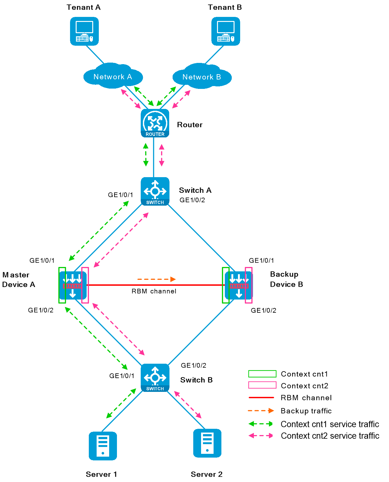
Figure-2 Network diagram for contexts cnt1
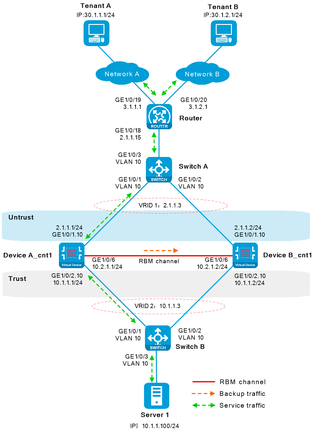
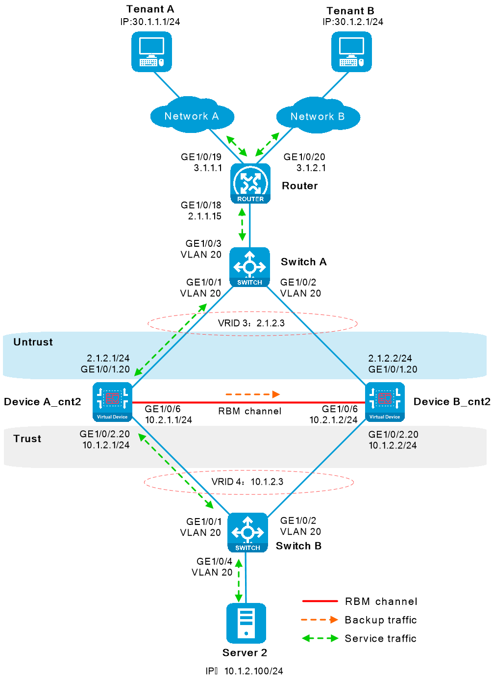
Figure-3 Network diagram for contexts cnt2
Software versions used
This configuration example was created and verified on R9900P2705 of the F5000-AI-55-G device.
Restrictions and guidelines
Member device restrictions and guidelines
A hot backup system can contain a maximum of two devices.
To ensure that the traffic size is within the processing capability of one device upon failure of the other device, make sure the throughput of each device does not exceed 50% of its capability.
Hardware environment consistency
Before you configure hot backup, verify that the following hardware settings are the same on the devices to be assigned to a hot backup system:
Device model.
Number and type of management interfaces, service interfaces, and interfaces for setting up the hot backup channels. Do not use one interface for multiple purposes.
Location, number, and type of disks. A device not with disks installed has small log storage and do not support some types of logs or reports.
Software environment consistency
Before you configure hot backup, verify that the following software settings are the same on the devices to be assigned to a hot backup system:
Software environment and version, including boot packages, system packages, feature packages, and patches.
Licensed signature libraries and features, such as signature library types, signature library version, validation time, and number of licensed resources.
Interface numbers.
Type, speed, and number of the interfaces for setting up the hot backup channels. As a best practice, use aggregate interfaces.
Aggregate interface numbers and aggregation member port numbers.
Security zone configuration on the interfaces at the same location.
Multi-CPU packet distribution policy (configurable with the
forwarding policy command).
Procedures
Configuring Router
Assign IP addresses to interfaces.
# Assign IPv4 addresses to service interfaces according to the network diagrams.
<Router> system-view
[Router] interface gigabitethernet 1/0/18
[Router-/0/18] ip address 2.1.1.15 255.255.255.0
[Router-/0/18] quit
[Router] interface gigabitethernet 1/0/19
[Router-/0/19] ip address 3.1.1.1 255.255.255.0
[Router-/0/19] quit
[Router] interface gigabitethernet 1/0/20
[Router-/0/20] ip address 3.1.2.1 255.255.255.0
[Router-/0/20] quit
Configure routes.
# To reach Server 1, configure a static route destined for 10.1.1.100/24, with the next hop IPv4 address being 2.1.1.3, the virtual IPv4 address of VRRP group 1. To reach Server 2, configure a static route destined for 10.1.2.100/24, with the next hop IPv4 address being 2.1.2.3, the virtual IPv4 address of VRRP group 3.
[Router] ip route-static 10.1.1.0 24 2.1.1.3
[Router] ip route-static 10.1.2.0 24 2.1.2.3
# Configure two static routes destined for the external network. In one static route, the destination network is 30.1.1.1, and the next hop IPv4 address is 3.1.1.15/24. In the other static route, the destination network is 30.1.2.1, and the next hop IPv4 address is 3.1.2.15/24.
[Router] ip route-static 30.1.1.0 24 3.1.1.15
[Router] ip route-static 30.1.2.0 24 3.1.2.15
Configuring Switch A
# Create VLAN 10 and VLAN 20, assign the interfaces facing Device B as trunk ports to the VLANs.
<SwitchA> system-view
[SwitchA] vlan 10
[SwitchA-vlan10] quit
[SwitchA] vlan 20
[SwitchA-vlan20] quit
[SwitchA] interface gigabitethernet 1/0/1
[SwitchA-/0/1] port link-type trunk
[SwitchA-/0/1] port trunk permit vlan 10 20
[SwitchA-/0/1] quit
[SwitchA] interface gigabitethernet 1/0/2
[SwitchA-/0/2] port link-type trunk
[SwitchA-/0/2] port trunk permit vlan 10 20
[SwitchA-/0/2] quit
[SwitchA] interface gigabitethernet 1/0/3
[SwitchA-/0/3] port link-type trunk
[SwitchA-/0/3] port trunk permit vlan 10 20
[SwitchA-/0/3] quit
Configuring Switch B
# Create VLAN 10 and VLAN 20, assign the interfaces facing Device A as trunk ports to the VLANs.
<SwitchB> system-view
[SwitchB] vlan 10
[SwitchB-vlan10] quit
[SwitchB] vlan 20
[SwitchB-vlan20] quit
[SwitchB] interface gigabitethernet 1/0/1
[SwitchB-/0/1] port link-type trunk
[SwitchB-/0/1] port trunk permit vlan 10 20
[SwitchB-/0/1] quit
[SwitchB] interface gigabitethernet 1/0/2
[SwitchB-/0/2] port link-type trunk
[SwitchB-/0/2] port trunk permit vlan 10 20
[SwitchB-/0/2] quit
[SwitchB] interface gigabitethernet 1/0/3
[SwitchB-/0/3] port access vlan 10
[SwitchB-/0/3] quit
[SwitchB] interface gigabitethernet 1/0/4
[SwitchB-/0/4] port access vlan 20
[SwitchB-/0/4] quit
Configuring Device A
Configure non-default context
cnt1 .Configure non-default context
cnt1 .<DeviceA> system-view
[DeviceA] context cnt1
[DeviceA-context-2-cnt1] allocate interface gigabitethernet 1/0/1 share
[DeviceA-context-2-cnt1] allocate interface gigabitethernet 1/0/2 share
[DeviceA-context-2-cnt1] context start
[DeviceA-context-2-cnt1] quit
Assign IP addresses to interfaces on non-default context
cnt1 .# Assign IPv4 addresses to service interfaces. For Ethernet subinterfaces to forward traffic, configure Dot1q VLAN termination.
[DeviceA] switchto context cnt1
<DeviceA> system-view
[DeviceA] sysname DeviceA_cnt1
[DeviceA_cnt1] interface gigabitethernet 1/0/1.10
[DeviceA_cnt1-/0/1.10] ip address 2.1.1.1 24
[DeviceA_cnt1-/0/1.10] vlan-type dot1q vid 10
[DeviceA_cnt1-/0/1.10] quit
[DeviceA_cnt1] interface gigabitethernet 1/0/2.10
[DeviceA_cnt1-/0/2.10] ip address 10.1.1.1 24
[DeviceA_cnt1-/0/2.10] vlan-type dot1q vid 10
[DeviceA_cnt1-/0/2.10] quit
Assign interfaces to security zones.
# Assign interfaces to security zones according to the network diagram.
[DeviceA_cnt1] security-zone name untrust
[DeviceA_cnt1-security-zone-Untrust] import interface gigabitethernet 1/0/1.10
[DeviceA_cnt1-security-zone-Untrust] quit
[DeviceA_cnt1] security-zone name trust
[DeviceA_cnt1-security-zone-Trust] import interface gigabitethernet 1/0/2.10
[DeviceA_cnt1-security-zone-Trust] quit
Configure static routes.
This example configures static routes. You can use other types of routes based on a live network.
# Configure a static route destined for the external network. In the static route, the next hop IPv4 address is 2.1.1.15.
[DeviceA_cnt1] ip route-static 0.0.0.0 0.0.0.0 2.1.1.15
Configure security policies to permit service packets.
Configure security policies on the primary device. After the hot backup system is set up, the secondary device will synchronize the security policies.
# Configure a security policy rule named trust-untrust to permit the traffic sent from the internal network 10.1.1.0/24 to the Internet and deny the traffic sent in the reverse direction.
[DeviceA_cnt1] security-policy ip
[DeviceA_cnt1-security-policy-ip] rule name trust-untrust
[DeviceA_cnt1-security-policy-ip-0-trust-untrust] source-zone trust
[DeviceA_cnt1-security-policy-ip-0-trust-untrust] destination-zone untrust
[DeviceA_cnt1-security-policy-ip-0-trust-untrust] source-ip-subnet 10.1.1.0 24
[DeviceA_cnt1-security-policy-ip-0-trust-untrust] action pass
[DeviceA_cnt1-security-policy-ip-0-trust-untrust] quit
# Configure security policy rules to permit VRRP protocol packets. When the RBM channels are disconnected, Device A and Device B can exchange VRRP protocol packets to elect a VRRP master.
[DeviceA_cnt1-security-policy-ip] rule name vrrp1
[DeviceA_cnt1-security-policy-ip-1-vrrp1] source-zone trust
[DeviceA_cnt1-security-policy-ip-1-vrrp1] destination-zone local
[DeviceA_cnt1-security-policy-ip-1-vrrp1] service vrrp
[DeviceA_cnt1-security-policy-ip-1-vrrp1] action pass
[DeviceA_cnt1-security-policy-ip-1-vrrp1] quit
[DeviceA_cnt1-security-policy-ip] rule name vrrp2
[DeviceA_cnt1-security-policy-ip-2-vrrp2] source-zone local
[DeviceA_cnt1-security-policy-ip-2-vrrp2] destination-zone trust
[DeviceA_cnt1-security-policy-ip-2-vrrp2] service vrrp
[DeviceA_cnt1-security-policy-ip-2-vrrp2] action pass
[DeviceA_cnt1-security-policy-ip-2-vrrp2] quit
[DeviceA_cnt1-security-policy-ip] rule name vrrp3
[DeviceA_cnt1-security-policy-ip-3-vrrp3] source-zone untrust
[DeviceA_cnt1-security-policy-ip-3-vrrp3] destination-zone local
[DeviceA_cnt1-security-policy-ip-3-vrrp3] service vrrp
[DeviceA_cnt1-security-policy-ip-3-vrrp3] action pass
[DeviceA_cnt1-security-policy-ip-3-vrrp3] quit
[DeviceA_cnt1-security-policy-ip] rule name vrrp4
[DeviceA_cnt1-security-policy-ip-4-vrrp4] source-zone local
[DeviceA_cnt1-security-policy-ip-4-vrrp4] destination-zone untrust
[DeviceA_cnt1-security-policy-ip-4-vrrp4] service vrrp
[DeviceA_cnt1-security-policy-ip-4-vrrp4] action pass
[DeviceA_cnt1-security-policy-ip-4-vrrp4] quit
[DeviceA_cnt1-security-policy-ip] quit
[DeviceA_cnt1] quit
<DeviceA_cnt1> quit
Configure non-default context
cnt 2 .Configure non-default context
cnt 2 .<DeviceA> system-view
[DeviceA] context cnt2
[DeviceA-context-3-cnt2] allocate interface gigabitethernet 1/0/1 share
[DeviceA-context-3-cnt2] allocate interface gigabitethernet 1/0/2 share
[DeviceA-context-3-cnt2] context start
[DeviceA-context-3-cnt2] quit
Assign IP addresses to interfaces on non-default context
cnt 2 .# Assign IPv4 addresses to service interfaces. For Ethernet subinterfaces to forward traffic, configure Dot1q VLAN termination.
[DeviceA] switchto context cnt2
<DeviceA> system-view
[DeviceA] sysname DeviceA_cnt2
[DeviceA_cnt2] interface gigabitethernet 1/0/1.20
[DeviceA_cnt2-/0/1.20] ip address 2.1.2.1 24
[DeviceA_cnt2-/0/1.20] vlan-type dot1q vid 20
[DeviceA_cnt2-/0/1.20] quit
[DeviceA_cnt2] interface gigabitethernet 1/0/2.20
[DeviceA_cnt2-/0/2.20] ip address 10.1.2.1 24
[DeviceA_cnt2-/0/2.20] vlan-type dot1q vid 20
[DeviceA_cnt2-/0/2.20] quit
Assign interfaces to security zones.
# Assign interfaces to security zones according to the network diagram.
[DeviceA_cnt2] security-zone name untrust
[DeviceA_cnt2-security-zone-Untrust] import interface gigabitethernet 1/0/1.20
[DeviceA_cnt2-security-zone-Untrust] quit
[DeviceA_cnt2] security-zone name trust
[DeviceA_cnt2-security-zone-Trust] import interface gigabitethernet 1/0/2.20
[DeviceA_cnt2-security-zone-Trust] quit
Configure static routes.
This example configures static routes. You can use other types of routes based on a live network.
# Configure a static route destined for the external network. In the static route, the next hop IPv4 address is 2.1.1.15.
[DeviceA_cnt2] ip route-static 0.0.0.0 0.0.0.0 2.1.1.15
Configure security policies to permit service packets.
Configure security policies on the primary device. After the hot backup system is set up, the secondary device will synchronize the security policies.
# Configure a security policy rule named trust-untrust to permit the traffic sent from the internal network 10.1.2.0/24 to the Internet and deny the traffic sent in the reverse direction.
[DeviceA_cnt2] security-policy ip
[DeviceA_cnt2-security-policy-ip] rule name trust-untrust
[DeviceA_cnt2-security-policy-ip-0-trust-untrust] source-zone trust
[DeviceA_cnt2-security-policy-ip-0-trust-untrust] destination-zone untrust
[DeviceA_cnt2-security-policy-ip-0-trust-untrust] source-ip-subnet 10.1.2.0 24
[DeviceA_cnt2-security-policy-ip-0-trust-untrust] action pass
[DeviceA_cnt2-security-policy-ip-0-trust-untrust] quit
# Configure security policy rules to permit VRRP protocol packets. When the RBM channels are disconnected, Device A and Device B can exchange VRRP protocol packets to elect a VRRP master.
[DeviceA_cnt2-security-policy-ip] rule name vrrp1
[DeviceA_cnt2-security-policy-ip-1-vrrp1] source-zone trust
[DeviceA_cnt2-security-policy-ip-1-vrrp1] destination-zone local
[DeviceA_cnt2-security-policy-ip-1-vrrp1] service vrrp
[DeviceA_cnt2-security-policy-ip-1-vrrp1] action pass
[DeviceA_cnt2-security-policy-ip-1-vrrp1] quit
[DeviceA_cnt2-security-policy-ip] rule name vrrp2
[DeviceA_cnt2-security-policy-ip-2-vrrp2] source-zone local
[DeviceA_cnt2-security-policy-ip-2-vrrp2] destination-zone trust
[DeviceA_cnt2-security-policy-ip-2-vrrp2] service vrrp
[DeviceA_cnt2-security-policy-ip-2-vrrp2] action pass
[DeviceA_cnt2-security-policy-ip-2-vrrp2] quit
[DeviceA_cnt2-security-policy-ip] rule name vrrp3
[DeviceA_cnt2-security-policy-ip-3-vrrp3] source-zone untrust
[DeviceA_cnt2-security-policy-ip-3-vrrp3] destination-zone local
[DeviceA_cnt2-security-policy-ip-3-vrrp3] service vrrp
[DeviceA_cnt2-security-policy-ip-3-vrrp3] action pass
[DeviceA_cnt2-security-policy-ip-3-vrrp3] quit
[DeviceA_cnt2-security-policy-ip] rule name vrrp4
[DeviceA_cnt2-security-policy-ip-4-vrrp4] source-zone local
[DeviceA_cnt2-security-policy-ip-4-vrrp4] destination-zone untrust
[DeviceA_cnt2-security-policy-ip-4-vrrp4] service vrrp
[DeviceA_cnt2-security-policy-ip-4-vrrp4] action pass
[DeviceA_cnt2-security-policy-ip-4-vrrp4] quit
[DeviceA_cnt2-security-policy-ip] quit
[DeviceA_cnt2] quit
<DeviceA_cnt2> quit
Configure hot backup.
Set up a hot backup system.
# Configure an IP address for setting up RBM channels.
[DeviceA] interface gigabitethernet 1/0/6
[DeviceA-/0/6] ip address 10.2.1.1 24
[DeviceA-/0/6] quit
# Configure Device A as the primary device and Device B as the secondary device. When Device A or its link fails, Device B takes over traffic forwarding to ensure service continuity.
[DeviceA] remote-backup group
[DeviceA-remote-backup-group] remote-ip 10.2.1.2
[DeviceA-remote-backup-group] local-ip 10.2.1.1
[DeviceA-remote-backup-group] data-channel interface gigabitethernet 1/0/6
[DeviceA-remote-backup-group] device-role primary
RBM_P[DeviceA-remote-backup-group] undo backup-mode
RBM_P[DeviceA-remote-backup-group] hot-backup enable
RBM_P[DeviceA-remote-backup-group] configuration auto-sync enable
RBM_P[DeviceA-remote-backup-group] configuration sync-check interval 12
RBM_P[DeviceA-remote-backup-group] delay-time 1
RBM_P[DeviceA-remote-backup-group] quit
# Create VRRP groups on the contexts and associate the VRRP groups with hot backup. Hot backup will centrally manage traffic forwarding.
RBM_P[DeviceA] switchto context cnt1
RBM_P<DeviceA_cnt1> system-view
RBM_P[DeviceA_cnt1] interface gigabitethernet 1/0/1.10
RBM_P[DeviceA_cnt1-/0/1.10] vrrp vrid 1 virtual-ip 2.1.1.3 active
RBM_P[DeviceA_cnt1-/0/1.10] quit
RBM_P[DeviceA_cnt1] interface gigabitethernet 1/0/2.10
RBM_P[DeviceA_cnt1-/0/2.10] vrrp vrid 2 virtual-ip 10.1.1.3 active
RBM_P[DeviceA_cnt1-/0/2.10] quit
RBM_P[DeviceA_cnt1] quit
RBM_P<DeviceA_cnt1> quit
RBM_P[DeviceA] switchto context cnt2
RBM_P<DeviceA_cnt2> system-view
RBM_P[DeviceA_cnt2] interface gigabitethernet 1/0/1.20
RBM_P[DeviceA_cnt2-/0/1.20] vrrp vrid 3 virtual-ip 2.1.2.3 active
RBM_P[DeviceA_cnt2-/0/1.20] quit
RBM_P[DeviceA_cnt2] interface gigabitethernet 1/0/2.20
RBM_P[DeviceA_cnt2-/0/2.20] vrrp vrid 4 virtual-ip 10.1.2.3 active
RBM_P[DeviceA_cnt2-/0/2.20] quit
RBM_P[DeviceA_cnt2] quit
RBM_P<DeviceA_cnt2> quit
Configure security services on Device A.
# Configure security services. If hot backup can back up configuration of a service module, configure the service module only on the primary device (Device A).
Configuring Device B
Configure non-default context
cnt1 .Configure non-default context
cnt1 .<DeviceB> system-view
[DeviceB] context cnt1
[DeviceB-context-2-cnt1] allocate interface gigabitethernet 1/0/1 share
[DeviceB-context-2-cnt1] allocate interface gigabitethernet 1/0/2 share
[DeviceB-context-2-cnt1] context start
[DeviceB-context-2-cnt1] quit
Assign IP addresses to interfaces on non-default context
cnt1 .# Assign IPv4 addresses to service interfaces. For Ethernet subinterfaces to forward traffic, configure Dot1q VLAN termination.
[DeviceB] switchto context cnt1
<DeviceB> system-view
[DeviceB] sysname DeviceB_cnt1
[DeviceB_cnt1] interface gigabitethernet1/0/1.10
[DeviceB_cnt1-/0/1.10] ip address 2.1.1.2 255.255.255.0
[DeviceB_cnt1-/0/1.10] vlan-type dot1q vid 10
[DeviceB_cnt1-/0/1.10] quit
[DeviceB_cnt1] interface gigabitethernet1/0/2.10
[DeviceB_cnt1-/0/2.10] ip address 10.1.1.2 255.255.255.0
[DeviceB_cnt1-/0/2.10] vlan-type dot1q vid 10
[DeviceB_cnt1-/0/2.10] quit
Assign interfaces to security zones.
# Assign interfaces to security zones according to the network diagram.
[DeviceB_cnt1] security-zone name untrust
[DeviceB_cnt1-security-zone-Untrust] import interface gigabitethernet 1/0/1.10
[DeviceB_cnt1-security-zone-Untrust] quit
[DeviceB_cnt1] security-zone name trust
[DeviceB_cnt1-security-zone-Trust] import interface gigabitethernet 1/0/2.10
[DeviceB_cnt1-security-zone-Trust] quit
Configure static routes.
This example configures static routes. You can use other types of routes based on a live network.
# Configure a static route destined for the external network. In the static route, the next hop IPv4 address is 2.1.1.15.
[DeviceB_cnt1] ip route-static 0.0.0.0 0.0.0.0 2.1.1.15
Configure non-default context
cnt 2 .Configure non-default context
cnt 2 .<DeviceB> system-view
[DeviceB] context cnt2
[DeviceB-context-2-cnt2] allocate interface gigabitethernet 1/0/1 share
[DeviceB-context-2-cnt2] allocate interface gigabitethernet 1/0/2 share
[DeviceB-context-2-cnt2] context start
[DeviceB-context-2-cnt2] quit
Assign IP addresses to interfaces on non-default context
cnt 2 .# Assign IPv4 addresses to service interfaces. For Ethernet subinterfaces to forward traffic, configure Dot1q VLAN termination.
[DeviceB] switchto context cnt2
<DeviceB> system-view
[DeviceB] sysname DeviceB_cnt2
[DeviceB_cnt2] interface gigabitethernet1/0/1.20
[DeviceB_cnt2-/0/1.20] ip address 2.1.2.2 255.255.255.0
[DeviceB_cnt2-/0/1.20] vlan-type dot1q vid 20
[DeviceB_cnt2-/0/1.20] quit
[DeviceB_cnt2] interface gigabitethernet1/0/2.20
[DeviceB_cnt2-/0/2.20] ip address 10.1.2.2 255.255.255.0
[DeviceB_cnt2-/0/2.20] vlan-type dot1q vid 20
[DeviceB_cnt2-/0/2.20] quit
Assign interfaces to security zones.
# Assign interfaces to security zones according to the network diagram.
[DeviceB_cnt2] security-zone name untrust
[DeviceB_cnt2-security-zone-Untrust] import interface gigabitethernet 1/0/1.20
[DeviceB_cnt2-security-zone-Untrust] quit
[DeviceB_cnt2] security-zone name trust
[DeviceB_cnt2-security-zone-Trust] import interface gigabitethernet 1/0/2.20
[DeviceB_cnt2-security-zone-Trust] quit
Configure static routes.
This example configures static routes. You can use other types of routes based on a live network.
# Configure a static route destined for the external network. In the static route, the next hop IPv4 address is 2.1.1.15.
[DeviceB_cnt2] ip route-static 0.0.0.0 0.0.0.0 2.1.1.15
Configure hot backup.
# Configure an IP address for setting up RBM channels.
[DeviceB] interface gigabitethernet 1/0/6
[DeviceB-/0/6] port link-mode route
[DeviceB-/0/6] ip address 10.2.1.2 255.255.255.0
[DeviceB-/0/6] quit
# Configure Device A as the primary device and Device B as the secondary device. When Device A or its link fails, Device B takes over traffic forwarding to ensure service continuity.
[DeviceB] remote-backup group
[DeviceB-remote-backup-group] remote-ip 10.2.1.1
[DeviceB-remote-backup-group] local-ip 10.2.1.2
[DeviceB-remote-backup-group] data-channel interface gigabitethernet 1/0/6
[DeviceB-remote-backup-group] device-role secondary
RBM_S[DeviceB-remote-backup-group] undo backup-mode
RBM_S[DeviceB-remote-backup-group] hot-backup enable
RBM_S[DeviceB-remote-backup-group] configuration auto-sync enable
RBM_S[DeviceB-remote-backup-group] configuration sync-check interval 12
RBM_S[DeviceB-remote-backup-group] delay-time 1
RBM_S[DeviceB-remote-backup-group] quit
# Create VRRP groups on the contexts and associate the VRRP groups with hot backup. Hot backup will centrally manage traffic forwarding.
RBM_S[DeviceB] switchto context cnt1
RBM_S<DeviceB_cnt1> system-view
RBM_S[DeviceB_cnt1] interface gigabitethernet 1/0/1.10
RBM_S[DeviceB_cnt1-/0/1.10] vrrp vrid 1 virtual-ip 2.1.1.3 standby
RBM_S[DeviceB_cnt1-/0/1.10] quit
RBM_S[DeviceB_cnt1] interface gigabitethernet 1/0/2.10
RBM_S[DeviceB_cnt1-/0/2.10] vrrp vrid 2 virtual-ip 10.1.1.3 standby
RBM_S[DeviceB_cnt1-/0/2.10] quit
RBM_S[DeviceB_cnt1] quit
RBM_S<DeviceB_cnt1> quit
RBM_S[DeviceB] switchto context cnt2
RBM_S<DeviceB_cnt2> system-view
RBM_S[DeviceB_cnt2] interface gigabitethernet 1/0/1.20
RBM_S[DeviceB_cnt2-/0/1.20] vrrp vrid 1 virtual-ip 2.1.2.3 standby
RBM_S[DeviceB_cnt2-/0/1.20] quit
RBM_S[DeviceB_cnt2] interface gigabitethernet 1/0/2.20
RBM_S[DeviceB_cnt2-/0/2.20] vrrp vrid 2 virtual-ip 10.1.2.3 standby
RBM_S[DeviceB_cnt2-/0/2.20] quit
RBM_S[DeviceB_cnt2] quit
RBM_S<DeviceB_cnt2> quit
Configuring servers
On Server 1, configure the default gateway as 10.1.1.3, the virtual IPv4 address of VRRP group 2. On Server 2, configure the default gateway as 10.1.2.3, the virtual IPv4 address of VRRP group 4.
Verifying the configuration
Verifying the configuration on Device A
Verify that the hot backup system has been set up and RBM channels have been established.
RBM_P[DeviceA] display remote-backup-group status
Remote backup group information:
Backup mode: Active/standby
Device management role: Primary
Device running status: Active
Data channel interface: GigE1/0/6
Local IP: 10.2.1.1
Remote IP: 10.2.1.2 Destination port: 60064
Control channel status: Connected
Keepalive interval: 1s
Keepalive count: 10
Configuration consistency check interval: 12 hour
Configuration consistency check result: Not Performed
Configuration backup status: Auto sync enabled
Session backup status: Hot backup enabled
Delay-time: 1 min
Uptime since last switchover: 0 days, 1 hours, 5 minutes
Switchover records:
Time Status change Cause
2022-11-26 14:39:42 Initial to Active Interface status changed
Verify the configuration on context
cnt1 .# Verify the status of VRRP groups.
RBM_P[DeviceA_cnt1] display vrrp
IPv4 Virtual Router Information:
Running mode : Standard
RBM control channel is established
VRRP active group status : Master
VRRP standby group status: Master
Total number of virtual routers : 2
Interface VRID State Running Adver Auth Virtual
Pri Timer Type IP
----------------------------------------------------------------------------
FGE1/0/1.10 1 Master 100 100 None 2.1.1.3
FGE1/0/2.10 2 Master 100 100 None 10.1.1.3
Verify the configuration on context
cnt 2 .# Verify the status of VRRP groups.
RBM_P[DeviceA_cnt2] display vrrp
IPv4 Virtual Router Information:
Running mode : Standard
RBM control channel is established
VRRP active group status : Master
VRRP standby group status: Master
Total number of virtual routers : 2
Interface VRID State Running Adver Auth Virtual
Pri Timer Type IP
----------------------------------------------------------------------------
FGE1/0/1.20 1 Master 100 100 None 2.1.2.3
FGE1/0/2.20 2 Master 100 100 None 10.1.2.3
Verifying the configuration on Device B
Verify that the hot backup system has been set up and RBM channels have been established.
RBM_S[DeviceB] display remote-backup-group status
Remote backup group information:
Backup mode: Active/standby
Device management role: Secondary
Device running status: Standby
Data channel interface: GigE1/0/6
Local IP: 10.2.1.2
Remote IP: 10.2.1.1 Destination port: 60064
Control channel status: Connected
Keepalive interval: 1s
Keepalive count: 10
Configuration consistency check interval: 12 hour
Configuration consistency check result: Not Performed
Configuration backup status: Auto sync enabled
Session backup status: Hot backup enabled
Delay-time: 1 min
Uptime since last switchover: 0 days, 0 hours, 28 minutes
Switchover records:
Time Status change Cause
2022-11-26 15:07:26 Initial to Standby Interface status changed
Verify the configuration on context
cnt1 .# Verify the status of VRRP groups.
RBM_S[DeviceB_cnt1] display vrrp
IPv4 Virtual Router Information:
Running mode : Standard
RBM control channel is established
VRRP active group status : Backup
VRRP standby group status: Backup
Total number of virtual routers : 2
Interface VRID State Running Adver Auth Virtual
Pri Timer Type IP
----------------------------------------------------------------------------
FGE1/0/1.10 1 Backup 100 100 None 2.1.1.3
FGE1/0/2.10 2 Backup 100 100 None 10.1.1.3
Verify the configuration on context
cnt 2 .# Verify the status of VRRP groups.
RBM_S[DeviceB_cnt2] display vrrp
IPv4 Virtual Router Information:
Running mode : Standard
RBM control channel is established
VRRP active group status : Backup
VRRP standby group status: Backup
Total number of virtual routers : 2
Interface VRID State Running Adver Auth Virtual
Pri Timer Type IP
----------------------------------------------------------------------------
FGE1/0/1.20 1 Backup 100 100 None 2.1.2.3
FGE1/0/2.20 2 Backup 100 100 None 10.1.2.3
Verifying traffic failover
Simulate failure of context cnt1 on Device A.
# When Device A is running correctly, shut down interfaces on the primary device for traffic to fail over to Device B over the RBM channels. Verify the session information on context cnt1 on Device B.
RBM_S<DeviceB_cnt1> display session table ipv4 source-ip 10.1.1.100 verbose
Slot 1:
Initiator:
Source IP/port: 10.1.1.100/3743
Destination IP/port: 3.1.1.100/2048
DS-Lite tunnel peer: -
VPN instance/VLAN ID/Inline ID: -/-/-
Protocol: ICMP(1)
Inbound interface: GigE1/0/2.10
Source security zone: Trust
Responder:
Source IP/port: 3.1.1.100/2048
Destination IP/port: 10.1.1.100/3743
DS-Lite tunnel peer: -
VPN instance/VLAN ID/Inline ID: -/-/-
Protocol: ICMP(1)
Inbound interface: GigE1/0/1.10
Source security zone: Untrust
State: ICMP_REPLY
Application: ICMP
Rule ID: 0
Rule name: trust-untrust
Start time: 2022-11-26 20:51:19 TTL: 29s
Initiator->Responder: 101 packets 8484 bytes
Responder->Initiator: 101 packets 8484 bytes
Simulate failure of context cnt2 on Device A.
# When Device A is running correctly, shut down the interfaces on the primary device for traffic to fail over to Device B over the RBM channels. Verify the session information on context cnt2 on Device B.
RBM_S<DeviceB_cnt2> display session table ipv4 source-ip 10.1.2.100 verbose
Slot 1:
Initiator:
Source IP/port: 10.1.2.100/3743
Destination IP/port: 3.1.2.100/2048
DS-Lite tunnel peer: -
VPN instance/VLAN ID/Inline ID: -/-/-
Protocol: ICMP(1)
Inbound interface: GigE1/0/2.10
Source security zone: Trust
Responder:
Source IP/port: 3.1.2.100/2048
Destination IP/port: 10.1.2.100/3743
DS-Lite tunnel peer: -
VPN instance/VLAN ID/Inline ID: -/-/-
Protocol: ICMP(1)
Inbound interface: GigE1/0/1.10
Source security zone: Untrust
State: ICMP_REPLY
Application: ICMP
Rule ID: 0
Rule name: trust-untrust
Start time: 2022-11-26 21:30:19 TTL: 31s
Initiator->Responder: 112 packets 8994 bytes
Responder->Initiator: 112 packets 8994 bytes
Configuration files
Router
#
interface/0/18
port link-mode route
ip address 2.1.1.15 255.255.255.0
#
interface/0/19
port link-mode route
ip address 3.1.1.1 255.255.255.0
#
interface/0/20
port link-mode route
ip address 3.1.2.1 255.255.255.0
#
ip route-static 10.1.1.0 24 2.1.1.3
ip route-static 10.1.2.0 24 2.1.2.3
ip route-static 30.1.1.0 24 3.1.1.15
ip route-static 30.1.2.0 24 3.1.2.15
#
Switch A
#
vlan 10
#
vlan 20
#
interface/0/1
port link-mode bridge
port link-type trunk
port trunk permit vlan 10 20
#
interface/0/2
port link-mode bridge
port link-type trunk
port trunk permit vlan 10 20
#
interface/0/3
port link-mode bridge
port link-type trunk
port trunk permit vlan 10 20
#
Switch B
#
vlan 10
#
vlan 20
#
interface/0/1
port link-mode bridge
port link-type trunk
port trunk permit vlan 10 20
#
interface/0/2
port link-mode bridge
port link-type trunk
port trunk permit vlan 10 20
#
interface/0/3
port link-mode bridge
port access vlan 10
#
interface/0/4
port link-mode bridge
port access vlan 20
#
Device A
#
context cnt1 id 2
context start
allocate interface GigabitEthernet1/0/1 to GigabitEthernet1/0/2 share
#
context cnt2 id 3
context start
allocate interface GigabitEthernet1/0/1 to GigabitEthernet1/0/2 share
#
interface/0/6
port link-mode route
ip address 10.2.1.1 255.255.255.0
#
remote-backup group
data-channel interface/0/6
configuration sync-check interval 12
delay-time 1
local-ip 10.2.1.1
remote-ip 10.2.1.2
device-role primary
#
Device A-Context cnt1
#
interface/0/1.10
ip address 2.1.1.1 255.255.255.0
vlan-type dot1q vid 10
vrrp vrid 1 virtual-ip 2.1.1.3 active
#
interface/0/2.10
ip address 10.1.1.1 255.255.255.0
vlan-type dot1q vid 10
vrrp vrid 2 virtual-ip 10.1.1.3 active
#
security-zone name Trust
import interface/0/2.10
#
security-zone name Untrust
import interface/0/1.10
#
ip route-static 0.0.0.0 0 2.1.1.15
#
security-policy ip
rule 0 name trust-untrust
action pass
source-zone trust
destination-zone untrust
source-ip-subnet 10.1.1.0 255.255.255.0
rule 1 name vrrp1
source-zone trust
destination-zone local
service vrrp
rule 2 name vrrp2
action pass
source-zone local
destination-zone trust
service vrrp
rule 3 name vrrp3
action pass
source-zone untrust
destination-zone local
service vrrp
rule 4 name vrrp4
action pass
source-zone local
destination-zone untrust
service vrrp
#
Device A-Context cnt2
#
interface/0/1.20
ip address 2.1.2.1 255.255.255.0
vlan-type dot1q vid 20
vrrp vrid 1 virtual-ip 2.1.2.3 active
#
interface/0/2.20
ip address 10.1.2.1 255.255.255.0
vlan-type dot1q vid 20
vrrp vrid 2 virtual-ip 10.1.2.3 active
#
security-zone name Trust
import interface/0/2.20
#
security-zone name Untrust
import interface/0/1.20
#
ip route-static 0.0.0.0 0 2.1.1.15
#
security-policy ip
rule 0 name trust-untrust
action pass
source-zone trust
destination-zone untrust
source-ip-subnet 10.1.2.0 255.255.255.0
rule 1 name vrrp1
source-zone trust
destination-zone local
service vrrp
rule 2 name vrrp2
action pass
source-zone local
destination-zone trust
service vrrp
rule 3 name vrrp3
action pass
source-zone untrust
destination-zone local
service vrrp
rule 4 name vrrp4
action pass
source-zone local
destination-zone untrust
service vrrp
#
Device B
#
context cnt1 id 2
context start
allocate interface GigabitEthernet1/0/1 to GigabitEthernet1/0/2 share
#
context cnt2 id 3
context start
allocate interface GigabitEthernet1/0/1 to GigabitEthernet1/0/2 share
#
interface/0/6
port link-mode route
ip address 10.2.1.2 255.255.255.0
#
remote-backup group
data-channel interface/0/6
configuration sync-check interval 12
delay-time 1
local-ip 10.2.1.2
remote-ip 10.2.1.1
device-role secondary
#
Device B-Context cnt1
#
interface/0/1.10
ip address 2.1.1.2 255.255.255.0
vlan-type dot1q vid 10
vrrp vrid 1 virtual-ip 2.1.1.3 standby
#
interface/0/2.10
ip address 10.1.1.2 255.255.255.0
vlan-type dot1q vid 10
vrrp vrid 2 virtual-ip 10.1.1.3 standby
#
ip route-static 0.0.0.0 0 2.1.1.15
#
security-zone name Trust
import interface/0/2.10
#
security-zone name Untrust
import interface/0/1.10
#
security-policy ip
rule 0 name trust-untrust
action pass
source-zone trust
destination-zone untrust
source-ip-subnet 10.1.1.0 255.255.255.0
rule 1 name vrrp1
source-zone trust
destination-zone local
service vrrp
rule 2 name vrrp2
action pass
source-zone local
destination-zone trust
service vrrp
rule 3 name vrrp3
action pass
source-zone untrust
destination-zone local
service vrrp
rule 4 name vrrp4
action pass
source-zone local
destination-zone untrust
service vrrp
#
Device B-Context cnt2
#
interface/0/1.20
ip address 2.1.2.2 255.255.255.0
vlan-type dot1q vid 20
vrrp vrid 1 virtual-ip 2.1.2.3 standby
#
interface/0/2.20
ip address 10.1.2.2 255.255.255.0
vlan-type dot1q vid 20
vrrp vrid 2 virtual-ip 10.1.2.3 standby
#
ip route-static 0.0.0.0 0 2.1.1.15
#
security-zone name Trust
import interface/0/2.20
#
security-zone name Untrust
import interface/0/1.20
#
security-policy ip
rule 0 name trust-untrust
action pass
source-zone trust
destination-zone untrust
source-ip-subnet 10.1.2.0 255.255.255.0
rule 1 name vrrp1
source-zone trust
destination-zone local
service vrrp
rule 2 name vrrp2
action pass
source-zone local
destination-zone trust
service vrrp
rule 3 name vrrp3
action pass
source-zone untrust
destination-zone local
service vrrp
rule 4 name vrrp4
action pass
source-zone local
destination-zone untrust
service vrrp
#