IPsec
This help contains the following topics:
Introduction
IP Security (IPsec) is defined by the IETF to provide interoperable, high-quality, cryptography-based security for IP communications. It is a Layer 3 VPN technology that transmits data in a secure channel established between two endpoints (such as two security gateways). Such a secure channel is usually called an IPsec tunnel.
IPsec is a security framework that has the following protocols and algorithms:
Authentication Header (AH).
Encapsulating Security Payload (ESP).
Internet Key Exchange (IKE).
Algorithms for authentication and encryption.
AH and ESP are security protocols that provide security services. IKE performs automatic key exchange.
Security protocols and encapsulation modes
Security protocols
IPsec comes with two security protocols, AH and ESP. They define how to encapsulate IP packets and the security services that they can provide.
AH defines the encapsulation of the AH header in an IP packet. AH can provide data origin authentication, data integrity, and anti-replay services to prevent data tampering, but it cannot prevent eavesdropping. Therefore, it is suitable for transmitting non-confidential data.
ESP defines the encapsulation of the ESP header and trailer in an IP packet. ESP can provide data encryption, data origin authentication, data integrity, and anti-replay services. Unlike AH, ESP can guarantee data confidentiality because it can encrypt the data before encapsulating the data to IP packets.
Both AH and ESP provide authentication services, but the authentication service provided by AH is stronger. In practice, you can choose either or both security protocols. When both AH and ESP are used, an IP packet is encapsulated first by ESP and then by AH.
Encapsulation modes
IPsec supports the following encapsulation modes:
Transport mode
The security protocols protect the upper layer data of an IP packet. You can use the transport mode when end-to-end security protection is required (the secured transmission start and end points are the actual start and end points of the data). The transport mode is typically used for protecting host-to-host communications.
Tunnel mode
The security protocols protect the entire IP packet. You must use the tunnel mode when the secured transmission start and end points are not the actual start and end points of the data packets (for example, when two gateways provide IPsec but the data start and end points are two hosts behind the gateways). The tunnel mode is typically used for protecting gateway-to-gateway communications
Authentication and encryption
Authentication algorithms
IPsec uses hash algorithms to perform authentication. A hash algorithm produces a fixed-length digest for an arbitrary-length message. IPsec peers respectively calculate message digests for each packet. The receiver compares the local digest with that received from the sender. IPsec supports the following types of authentication algorithms:
Hash-based Message Authentication Code (HMAC) based authentication algorithms, including HMAC-MD5 and HMAC-SHA.
HMAC-MD5 is faster but less secure than HMAC-SHA.
SM3 authentication algorithms.
Encryption algorithms
IPsec uses symmetric encryption algorithms, which encrypt and decrypt data by using the same keys. The following encryption algorithms are available for IPsec on the device:
DES —Encrypts a 64-bit plaintext block with a 56-bit key. DES is the least secure but the fastest algorithm.3DES —Encrypts plaintext data with three 56-bit DES keys. The key length totals up to 168 bits. It provides moderate security strength and is slower than DES.AES —Encrypts plaintext data with a 128-bit, 192-bit, or 256-bit key. AES provides the highest security strength and is slower than 3DES.SM —Encrypts plaintext data with a 128-bit key. SM provides the same level of security strength as AES.
IPsec SA
A security association (SA) is an agreement negotiated between two IPsec peers. An SA includes the following parameters for data protection:
Security protocols.
Encapsulation mode.
Authentication algorithm.
Encryption algorithm.
Shared keys and their lifetimes.
An SA is unidirectional. At least two SAs are needed to protect data flows in a bidirectional communication. If two peers want to use both AH and ESP to protect data flows between them, they construct an independent SA for each protocol in each direction.
An SA is uniquely identified by a triplet, which consists of the security parameter index (SPI), destination IP address, and security protocol identifier. An SPI is a 32-bit number. It is transmitted in the AH/ESP header.
An IKE-created SA has a lifetime and will be deleted when its time-based or traffic-based lifetime timer expires. Before the SA lifetime timer expires, IKE negotiates a new SA, which takes over immediately after its creation.
IKE negotiation
IKE negotiates SAs for IPsec and transfers the SAs to IPsec, and IPsec uses the SAs to protect IP packets. IKE negotiates keys and SAs for IPsec in two phases:
Phase 1 —The two peers establish an IKE SA, a secure, authenticated channel for communication.Phase 1 negotiation can use the main mode, aggressive mode, or GM main mode. The aggressive mode is faster than the main mode but it does not provide identity information protection. The main mode provides identity information protection but is slower. Choose the appropriate negotiation mode according to your requirements. The GM main mode must be used if the local IKE peer uses the RSA-DE or SM2-DE digital envelop authentication method.
Phase 2 —Using the IKE SA established in phase 1, the two peers negotiate to establish IPsec SAs to protect IP packets.
IPsec tunnel establishment
Two peers establish an IPsec tunnel in between by applying an IPsec policy to an interface. An IPsec policy defines the range of packets to be protected by IPsec and the security parameters used for the protection.
When an IPsec peer identifies the packets to be protected according to the security policy, it sets up an IPsec tunnel and sends the packet to the remote peer through the tunnel. The IPsec tunnel can be set up through IKE negotiation triggered by the packet. The IPsec tunnels are actually the IPsec SAs. The inbound packets are protected by the inbound SA, and the outbound packets are protected by the outbound SA.
When sending a packet, an interface configured with IPsec policies looks through the IPsec policies in ascending order of policy priorities. If the packet matches a protected flow of an IPsec policy, the interface encapsulates the packet according to the IPsec policy. If no match is found, the interface sends the packet out without IPsec protection.
When the interface receives an IPsec packet destined for the local device, it searches for the inbound IPsec SA according to the SPI in the IPsec packet header for de-encapsulation. If the de-encapsulated packet matches a protected data flow, the device processes the packet. If the de-encapsulated packet does not match a protected data flow, the device drops the packet.
In an IPsec policy, you can specify whether to protect a data flow by selecting the action (Protect or Do not protect). You can define multiple data flows in an IPsec policy. The device processes a packet according to the action defined in the first matching data flow of the packet.
Both inbound and outbound packets of an interface need to match the data flows defined in the IPsec policy. The device performs forward matching of the data flows for outbound packets and backward matching of the data flows for inbound packets.
In outbound direction, packets that match "protect" data flows will be protected by IPsec. Packets that match no data flows or match "unprotect" data flows will not be protected by IPsec.
In inbound direction, non-IPsec packets that match "protect" data flows will be dropped. IPsec packets destined for the local device will be de-encapsulated.
IPsec smart link selection
To improve network stability and availability, multiple links are typically deployed at the network egress to connect to the destination network. The qualities of these links (in terms of packet loss ratio and delay) are not static but keep changing with time. It is important that the gateway device can dynamically select a link with desired transmission quality to establish the IPsec tunnel to the destination. IPsec smart link selection can meet this requirement.
IPsec smart link selection enables the gateway to monitor the real-time packet loss ratio and delay of the active link over which the IPsec tunnel is established. If the packet loss ratio or delay of the link exceeds the specified threshold, IPsec smart link selection reselects a link for the IPsec tunnel. You can also manually activate a link to establish the IPsec tunnel over that link.
IPsec smart link selection provides the following benefits:
Avoid the condition that some links are busy and some links are idle when multiple links are deployed at the network egress for load balancing.
Select proper links for customers when they cannot select links by themselves.
Avoid forwarding traffic to a failed link between the network egress device and the destination device.
Automatic generation of security policies
If you select
vSystem support information
Support of non-default vSystems for this feature depends on the device model. This feature is available on the Web interface only if it is supported.
Restrictions and guidelines
When you specify the remote host name in an IPsec policy, follow these restrictions and guidelines:
If the remote host name is resolved by a DNS server, the local device gets the latest IP address corresponding to the host name by sending a query to the DNS server when the cached DNS entry ages. The DNS entry aging information is obtained from the DNS server.
If the remote host name is resolved by a locally configured static DNS entry and the IP address in the entry is changed, you must respecify the remote host name in the IPsec policy to get the new IP address.
To make sure SAs can be set up and the traffic protected by IPsec can be processed correctly between two IPsec peers, create mirror image ACLs on the IPsec peers. If the ACL rules on IPsec peers do not form mirror images of each other, SAs can be set up only when both of the following requirements are met:
The range specified by an ACL rule on one peer is covered by its counterpart ACL rule on the other peer.
The peer with the narrower rule initiates SA negotiation.
If a wider ACL rule is used by the SA initiator, the negotiation request might be rejected because the matching traffic is beyond the scope of the responder.
If you do not configure the local identity in an IPsec policy, the policy uses the global local identity settings configured in the advanced settings.
Modifications to the following settings in an IPsec policy take effect only on IPsec SAs set up after the modifications:
Encapsulation mode.
Security protocol.
Security algorithms.
PFS.
IPsec SA lifetimes.
IPsec SA idle timeout.
For the modifications to take effect on existing IPsec SAs, you must reset the IPsec SAs.
The IPsec peers of an IPsec tunnel must have IPsec policies that use the same security protocols, security algorithms, and encapsulation mode.
When IKE negotiates IPsec SAs, it uses the IPsec SA lifetime settings configured in the IPsec policy to negotiate the IPsec SA lifetime with the peer. If the IPsec SA lifetime settings are not configured in the IPsec policy, the global IPsec SA lifetime settings are used. IKE uses the local lifetime settings or those proposed by the peer, whichever are smaller.
If a link used by smart link selection uses the gateway address as the next hop address, you must manually change the link next hop address whenever the gateway address is changed.
Configure IPsec
Prerequisites
Complete the following tasks before you configure this feature:
Assign IP addresses to interfaces on the
Network >Interface Configuration >Interfaces page.Configure routes on the
Network >Routing page. Make sure the routes are available.Create security zones on the
Network >Security Zones page.Add interfaces to security zones. You can add interfaces to a security zone on the
Security Zones page or select a security zone for an interface on theInterfaces page.Configure security policies to permit the target traffic on the
Policies >Security Policies page.
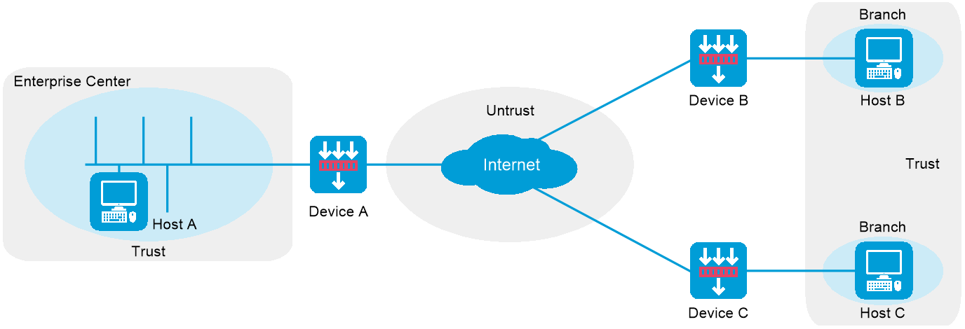
Configure IPsec in P2P mode
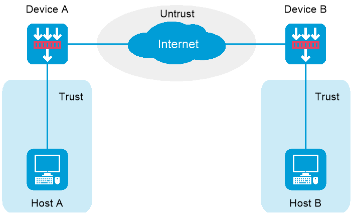
IPsec supports the peer-to-peer (P2P) or point-to-multipoint (P2MP) networking mode. As shown in Figure-1, in P2P mode, Host A and Host B communicate with each other through the Internet. Configure an IPsec tunnel between Device A and Device B to secure the communication between Host A and Host B.
Figure-1 IPsec network diagram in P2P mode
Configure basic IPsec settings
Click the
Network tab.Select
VPN >IPsec >IPsec Policies .Click
Create .Create an IPsec policy.
Make sure
Peer/branch gateway is selected in theDevice type field.Figure-2 Creating an IPsec policy
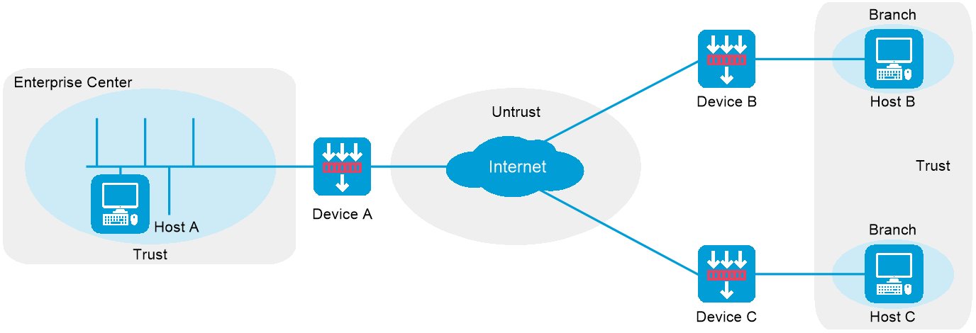
Table-1 Configuration items for basic IPsec settings
Item
Description
Policy name
Specify a name for the IPsec policy to uniquely identify the IPsec policy locally
Multiple IPsec policies can be created on the device.
Priority
Specify a sequence number for the IPsec policy.
An IPsec policy is a set of IPsec policy entries that have the same name but different sequence numbers. In the same IPsec policy, an IPsec policy entry with a smaller sequence number has a higher priority. When sending a packet, the interface applied with an IPsec policy looks through the IPsec policy's entries in ascending order of sequence numbers.
Alias
Alias of the IPsec policy.
Device type
Specify the role of the device in the IPsec network. Options include:
Peer/branch gateway —Select this option if you configure a branch device in P2MP mode or configure the peer device in P2P mode.Headquarters gateway —Select this option if you configure the center device in P2MP mode.
IP version
Specify the IP version for the local end address of the IPsec tunnel. Options include
IPv4 andIPv6 .Smart link selection
Specify whether to enable smart link selection.
IPsec smart link selection enables the branch gateway to monitor the real-time packet loss ratio and delay of the active link over which the IPsec tunnel is established. If the packet loss ratio or delay of the link exceeds the specified threshold, IPsec smart link selection reselects a link for the IPsec tunnel. IPsec smart link selection is not supported on IPv6 networks.
Interface
Specify the interface where the IPsec policy is applied.
If you enable smart link selection, specify all interfaces to be selected on the local end for smart link selection.
Local address
Specify the IP address of the interface where the IPsec policy is applied.
If you enable smart link selection, specify the IP addresses of all interfaces to be selected on the local end for smart link selection.
Remote IP/hostname
Specify the peer IP address or hostname of the IPsec tunnel.
If you enable smart link selection, specify the IP addresses of all peer interfaces for smart link selection.
Description
Enter a description for the IPsec policy.
Configure IKE profile settings
Go to the
IKE profile settings area.Configure related parameters.
Figure-3 Configuring IKE profile settings
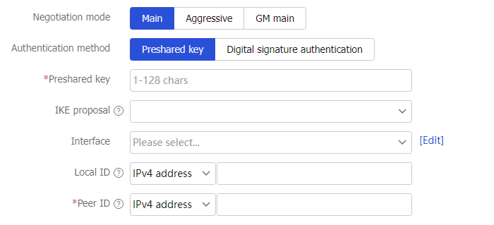
Table-2 Configuration items for IKE profile settings
Item
Description
Negotiation mode
Specify the IKE negotiation mode. Options include:
Main —The main mode provides secure protection.Aggressive —The aggressive mode is faster than the main mode.GM main —In GM main mode, the two IKE peers must use the RSA-DE or SM2-DE digital envelope authentication method. The IKE exchange process in GM main mode is similar to that in main mode. The GM main mode has a higher security.
Authentication method
Specify the authentication method. Options include:
Preshared key —If you specify the preshared key authentication method, two communicating peers use the pre-configured shared key for identity authentication. In P2P mode, the preshared key configured on the local device must be the same as that on the peer device.Digital signature authentication —Two communicating peers use the digital certificates issued by the CA for identity authentication. Digital signature authentication requires configuration of a PKI domain and certificate access control policy instead of preshared keys. For more information about PKI domains and certificate access control policies, see PKI online help.
Preshared key
Specify the preshared key.
This field is required if you specify the authentication method as
Preshared key . In P2P mode, the preshared key configured on the local device must be the same as that on the peer device.PKI domain
Specify the PKI domain.
This field is required if you specify the authentication method as
Digital signature authentication . PKI is an asymmetric key infrastructure to encrypt and decrypt data for securing network services. For more information about PKI configuration, see PKI online help.Cert access control policy
Specify the certificate access control policy.
This field is optional if you specify the authentication method as
Digital signature authentication . Certificate access control policies allow you to authorize access to a device (for example, an HTTPS server) based on the attributes of an authenticated client's certificate. For more information about configuration of certificate access control policies, see PKI online help.IKE proposal
Specify the IKE proposal.
An IKE proposal defines a set of attributes describing how IKE negotiation in phase 1 should take place. Options include:
Create IKE proposal —The IKE proposal parameters must be the same on both ends. For descriptions of the parameters, see "Configure IKE proposals ."NONE —Does not create an IKE proposal. Use the default IKE proposal for IKE negotiation.
Interface
Specify the interface where the IKE profile is applied.
Local ID
Specify the local ID.
The device uses the ID to identify itself to the peer during IKE negotiation. The local ID parameters configured on the local device must be the same as the peer ID parameters configured on the peer device. Options include:
IPv4 address —Use the IPv4 address of the local interface.IPv6 address —Use the IPv6 address of the local interface.FQDN —Use the local FQDN.User-FQDN —Use the local user FQDN.
Peer ID
Specify the peer ID.
The ID is used to identify the peer device during IKE negotiation. To obtain parameters about the peer ID, contact the administrator of the peer device. The peer ID parameters configured on the local device must be the same as the local ID parameters configured on the peer device. Options include:
IPv4 address —Use the IPv4 address of the peer interface.IPv6 address —Use the IPv6 address of the peer interface.FQDN —Use the peer's FQDN.User-FQDN —Use the peer's user FQDN.
Configure data flow filter rules
Go to the
D ata flow filter rules area.Click
Create .Configure related parameters.
Figure-4 Configuring a data flow filter rule
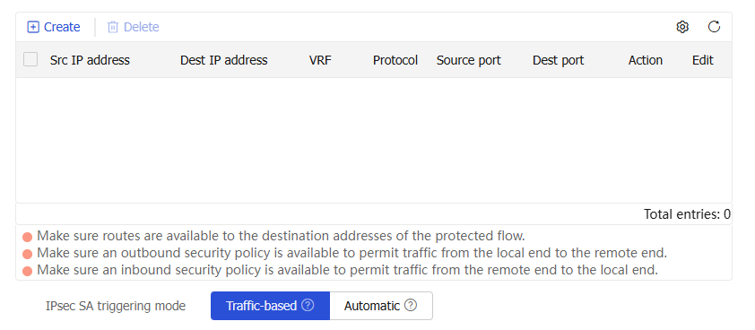
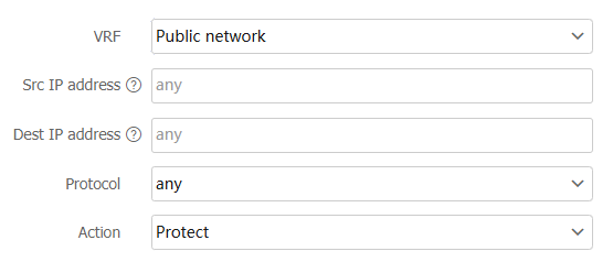
Table-3 Configuration items for data flow filter rules
Item
Description
VRF
Specify the VRF to which the protected data flow belongs.
Public network—The protected data flow belongs to the public network.
Select a created VRF or create a VRF—The protected data flow belongs to the specified VRF. Configure a VRF on the window that opens. For more information about VRF configuration, see VRF online help.
Src IP address
Specify the source IP address for the protected data flow.
An IP address or subnet address is supported. To not limit the source IP address, use the default value
any .Dest IP address
Specify the destination IP address for the protected data flow.
An IP address or subnet address is supported. To not limit the destination IP address, use the default value
any .Protocol
Select a protocol for the protected data flow. Options include:
any .TCP .UDP .ICMP .
Action
Specify the action on data flow matching the above requirements. Options include:
Protect —Allow the data flow to be forwarded into the tunnel.Do not protect —Do not allow the data flow to be forwarded into the tunnel.
IPsec SA triggering mode
Specify the IPsec SA negotiation triggering mode. Options include:
Traffic-based —Triggers SA negotiation when traffic requires IPsec protection.A utomatic —Triggers SA negotiation when required IPsec configuration is complete.
Configure advanced IPsec settings
Go to the
Advanced settings area.Configure related parameters.
Figure-5 Configuring advanced IPsec settings
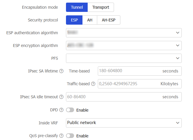
Table-4 Configuration items for advanced IPsec settings
Item
Description
Encapsulation mode
Specify the encapsulation mode. Options include:
Tunnel —The security protocols in tunnel mode protect the entire IP packet.Transport —The security protocols in transport mode protect the upper layer data of an IP packet.
Security protocol
Specify the security protocol for the IPsec-protected packets. Options include:
ESP —Provides authentication and encryption for the payload of an IP packet. ESP provides a weaker authentication service than AH.AH —Authenticates the entire IP packet, but does not provide encryption and cannot prevent eavesdropping.AH-ESP —Provides authentication and encryption for the entire IP packet, improving the integral security.
ESP authentication algorithm
Specify the authentication algorithms for ESP.
This field is required if you specify the security protocol as
ESP orAH-ESP . The ESP authentication algorithm configured on both ends must be the same. Options include:MD5 —Specify the HMAC-MD5-96 algorithm, which uses a 128-bit key.SHA1 —Specify the HMAC-SHA1-96 algorithm, which uses a 160-bit key.SHA256 —Specify the HMAC-SHA256 algorithm, which uses a 256-bit key.SHA384 —Specify the HMAC-SHA384 algorithm, which uses a 384-bit key.SHA512 —Specify the HMAC-SHA512 algorithm, which uses a 512-bit key.SM3 —Specify the HMAC-SM3-96 algorithm, which uses a 256-bit key.
ESP encryption algorithm
Specify the encryption algorithms for ESP.
This field is required if you specify the security protocol as
ESP orAH-ESP . The ESP encryption algorithm configured on both ends must be the same. Options include:3DES-CBC —Specify the 3DES algorithm in CBC mode, which uses a 168-bit key.AES-CBC-128 —Specify the AES algorithm in CBC mode, which uses a 128-bit key.AES-CBC-192 —Specify the AES algorithm in CBC mode, which uses a 192-bit key.AES-CBC-256 —Specify the AES algorithm in CBC mode, which uses a 256-bit key.DES-CBC —Specify the DES algorithm in CBC mode, which uses a 64-bit key.NULL —Specify the NULL algorithm, which means encryption is not performed.SM1-CBC-128 —Specify the SM1 algorithm in CBC mode, which uses a 128-bit key. This option is available only for IKEv1.SM4-CBC —Specify the SM4 algorithm in CBC mode, which uses a 128-bit key. This option is available only for IKEv1.
AH authentication algorithm
Specify the authentication algorithms for AH.
This field is required if you specify the security protocol as
AH orAH-ESP . The AH authentication algorithm configured on both ends must be the same. Options include:MD5 —Specify the HMAC-MD5-96 algorithm, which uses a 128-bit key.SHA1 —Specify the HMAC-SHA1-96 algorithm, which uses a 160-bit key.SHA256 —Specify the HMAC-SHA256 algorithm, which uses a 256-bit key.SHA384 —Specify the HMAC-SHA384 algorithm, which uses a 384-bit key.SHA512 —Specify the HMAC-SHA512 algorithm, which uses a 512-bit key.SM3 —Specify the HMAC-SM3-96 algorithm, which uses a 256-bit key. This option is available only for IKEv1.
PFS
Specify the Perfect Forward Secrecy (PFS) used by the IPsec policy for negotiation.
The PFS feature is a security feature that guarantees keys have no derivative relations. The higher the group number, the longer the key length, the higher the security, and the longer the calculation time. Options include:
Group_1 —Use 768-bit Diffie-Hellman group.Group_2 —Use 1024-bit Diffie-Hellman group.Group_5 —Use 1536-bit Diffie-Hellman group.Group_14 —Use 2048-bit Diffie-Hellman group.Group_24 —Use 2048-bit and 256-bit subgroup Diffie-Hellman group.
IPsec SA lifetime
Specify the IPsec SA lifetime.
An IPsec SA expires when the time-based or traffic-based lifetime is reached, whichever comes first. Options include:
Time-based —Specify how long the SA can exist after it is created.Traffic-based —Specify the maximum traffic that the SA can process.
IPsec SA idle timeout
Specify the IPsec SA idle timeout.
If no traffic matches the IPsec SA within the idle timeout interval, the IPsec SA is deleted.
DPD
Specify whether to enable DPD.
DPD detects if the IKE peer on the remote device is dead. If you select to enable DPD, configure the following parameters:
DPD mode —Specify the DPD mode. Options include:O n-demand DPD —Triggers DPD on demand.P eriodic DPD —Triggers DPD at regular intervals.
DPD triggering interval —Specify the DPD triggering interval.DPD retry interval —Specify the DPD retry interval.
Inside VRF
Specify the VRF to which the IP address of the IPsec peer belongs.
Public network—The IP address of the IPsec peer belongs to the public network.
Select a created VRF or create a VRF—The IP address of the IPsec peer belongs to the specified VRF. Configure a VRF on the window that opens. For more information about VRF configuration, see VRF online help.
QoS pre-classfy
Specify whether to enable QoS pre-classify.
With this feature enabled, QoS classifies packets by using the IP headers of the original IP packets. With this feature disabled, QoS classifies packets by using the new IP headers added by IPsec.
Configure security policy settings
Go to the
Security Policy area.Specify whether to enable
Auto-generate security policy .With this feature enabled, the device automatically generates security policies that permit IPsec and IKE negotiation packets.
Figure-6
Auto-generate security policy 
Click
OK . The new IPsec policy will appear in the IPsec policy list. When data flows are present, you can view the flow information in the tunnel details.
Configure IPsec in P2MP mode
IPsec supports the P2P or P2MP networking mode. As shown in Figure-7, in P2MP mode, Host A is at the enterprise center, and Host B and Host C are at two branches of the enterprise. Configure an IPsec tunnel between the headquarters gateway and each branch gateway to protect the traffic between Host A and each branch host.
Figure-7 IPsec network diagram in P2MP mode
Configure basic IPsec settings
Click the
Network tab.Select
VPN >IPsec >IPsec Policies .Click
Create .Create an IPsec policy.
Make sure
Headquarters gateway is selected in theDevice type field.Figure-8 Creating an IPsec policy
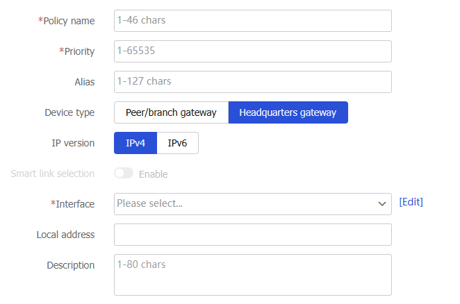
Table-5 Configuration items for basic IPsec settings
Item
Description
Policy name
Specify a name for the IPsec policy to uniquely identify the IPsec policy locally
Multiple IPsec policies can be created on the device.
Priority
Specify a sequence number for the IPsec policy.
An IPsec policy is a set of IPsec policy entries that have the same name but different sequence numbers. In the same IPsec policy, an IPsec policy entry with a smaller sequence number has a higher priority. When sending a packet, the interface applied with an IPsec policy looks through the IPsec policy's entries in ascending order of sequence numbers.
Device type
Specify the role of the device in the IPsec network. Options include:
Peer/branch gateway —Select this option if you configure a branch device in P2MP mode or configure the peer device in P2P mode.Headquarters gateway —Select this option if you configure the center device in P2MP mode.
Alias
Alias of the IPsec policy.
IP version
Specify the IP version for the local end address of the IPsec tunnel. Options include
IPv4 andIPv6 .Interface
Specify the interface where the IPsec policy is applied.
Local address
Specify the IP address of the interface where the IPsec policy is applied.
Description
Enter a description for the IPsec policy.
Configure IKE profile settings
Go to the
IKE profile settings area.Configure related parameters.
Figure-9 Configuring IKE profile settings
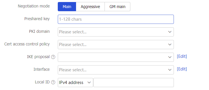
Table-6 Configuration items for IKE profile settings
Item
Description
Negotiation mode
Specify the IKE negotiation mode. Options include:
Main —The main mode provides secure protection.Aggressive —The aggressive mode is faster than the main mode.GM main —In GM main mode, the two IKE peers must use the RSA-DE or SM2-DE digital envelope authentication method. The IKE exchange process in GM main mode is similar to that in main mode. The GM main mode has a higher security.
Preshared key
Specify the preshared key.
This field is required if you specify the authentication method as
Preshared key on the branch node. In P2MP mode, the preshared key configured on the local device must be the same as that on the peer device.PKI domain
Specify the PKI domain.
This field is required if you specify the authentication method as
Digital signature authentication on the branch node. PKI is an asymmetric key infrastructure to encrypt and decrypt data for securing network services. For more information about PKI configuration, see PKI online help.Cert access control policy
Specify the certificate access control policy.
This field is optional if you specify the authentication method as
Digital signature authentication on the branch node. Certificate access control policies allow you to authorize access to a device (for example, an HTTPS server) based on the attributes of an authenticated client's certificate. For more information about configuration of certificate access control policies, see PKI online help.IKE proposal
Specify the IKE proposal.
An IKE proposal defines a set of attributes describing how IKE negotiation in phase 1 should take place. Options include:
Create IKE proposal —The IKE proposal parameters must be the same on both ends. For descriptions of the parameters, see "Configure IKE proposals ."NONE —Does not create an IKE proposal. Use the default IKE proposal for IKE negotiation.
Interface
Specify the interface where the IKE profile is applied.
Local ID
Specify the local ID.
The device uses the ID to identify itself to the peer during IKE negotiation. The local ID parameters configured on the local device must be the same as the peer ID parameters configured on the peer device. Options include:
IPv4 address —Use the IPv4 address of the local interface.IPv6 address —Use the IPv6 address of the local interface.FQDN —Use the local FQDN.User-FQDN —Use the local user FQDN.
Configure advanced IPsec settings
Go to the
Advanced settings area.Configure related parameters.
Figure-10 Configuring advanced IPsec settings

Table-7 Configuration items for advanced IPsec settings
Item
Description
Encapsulation mode
Specify the encapsulation mode. Options include:
Tunnel —The security protocols in tunnel mode protect the entire IP packet.Transport —The security protocols in transport mode protect the upper layer data of an IP packet.
Security protocol
Specify the security protocol for the IPsec-protected packets. Options include:
ESP —Provides authentication and encryption for the payload of an IP packet. ESP provides a weaker authentication service than AH.AH —Authenticates the entire IP packet, but does not provide encryption and cannot prevent eavesdropping.AH-ESP —Provides authentication and encryption for the entire IP packet, improving the integral security.
ESP authentication algorithm
Specify the authentication algorithms for ESP.
This field is required if you specify the security protocol as
ESP orAH-ESP . The ESP authentication algorithm configured on both ends must be the same. Options include:MD5 —Specify the HMAC-MD5-96 algorithm, which uses a 128-bit key.SHA1 —Specify the HMAC-SHA1-96 algorithm, which uses a 160-bit key.SHA256 —Specify the HMAC-SHA256 algorithm, which uses a 256-bit key.SHA384 —Specify the HMAC-SHA384 algorithm, which uses a 384-bit key.SHA512 —Specify the HMAC-SHA512 algorithm, which uses a 512-bit key.SM3 —Specify the HMAC-SM3-96 algorithm, which uses a 256-bit key.
ESP encryption algorithm
Specify the encryption algorithms for ESP.
This field is required if you specify the security protocol as
ESP orAH-ESP . The ESP encryption algorithm configured on both ends must be the same. Options include:3DES-CBC —Specify the 3DES algorithm in CBC mode, which uses a 168-bit key.AES-CBC-128 —Specify the AES algorithm in CBC mode, which uses a 128-bit key.AES-CBC-192 —Specify the AES algorithm in CBC mode, which uses a 192-bit key.AES-CBC-256 —Specify the AES algorithm in CBC mode, which uses a 256-bit key.DES-CBC —Specify the DES algorithm in CBC mode, which uses a 64-bit key.NULL —Specify the NULL algorithm, which means encryption is not performed.SM1-CBC-128 —Specify the SM1 algorithm in CBC mode, which uses a 128-bit key. This option is available only for IKEv1.SM4-CBC —Specify the SM4 algorithm in CBC mode, which uses a 128-bit key. This option is available only for IKEv1.
AH authentication algorithm
Specify the authentication algorithms for AH.
This field is required if you specify the security protocol as
AH orAH-ESP . The AH authentication algorithm configured on both ends must be the same. Options include:MD5 —Specify the HMAC-MD5-96 algorithm, which uses a 128-bit key.SHA1 —Specify the HMAC-SHA1-96 algorithm, which uses a 160-bit key.SHA256 —Specify the HMAC-SHA256 algorithm, which uses a 256-bit key.SHA384 —Specify the HMAC-SHA384 algorithm, which uses a 384-bit key.SHA512 —Specify the HMAC-SHA512 algorithm, which uses a 512-bit key.SM3 —Specify the HMAC-SM3-96 algorithm, which uses a 256-bit key. This option is available only for IKEv1.
PFS
Specify the Perfect Forward Secrecy (PFS) used by the IPsec policy for negotiation.
The PFS feature is a security feature that guarantees keys have no derivative relations. The higher the group number, the longer the key length, the higher the security, and the longer the calculation time. Options include:
Group_1 —Use 768-bit Diffie-Hellman group.Group_2 —Use 1024-bit Diffie-Hellman group.Group_5 —Use 1536-bit Diffie-Hellman group.Group_14 —Use 2048-bit Diffie-Hellman group.Group_24 —Use 2048-bit and 256-bit subgroup Diffie-Hellman group.
IPsec SA lifetime
Specify the IPsec SA lifetime.
An IPsec SA expires when the time-based or traffic-based lifetime is reached, whichever comes first. Options include:
Time-based —Specify how long the SA can exist after it is created.Traffic-based —Specify the maximum traffic that the SA can process.
IPsec SA idle timeout
Specify the IPsec SA idle timeout.
If no traffic matches the IPsec SA within the idle timeout interval, the IPsec SA is deleted.
DPD
Specify whether to enable DPD.
DPD detects if the IKE peer on the remote device is dead. If you select to enable DPD, configure the following parameters:
DPD mode —Specify the DPD mode. Options include:O n-demand DPD —Triggers DPD on demand.P eriodic DPD —Triggers DPD at regular intervals.
DPD triggering interval —Specify the DPD triggering interval.DPD retry interval —Specify the DPD retry interval.
Inside VRF
Specify the VRF to which the IP address of the IPsec peer belongs.
Public network—The IP address of the IPsec peer belongs to the public network.
Select a created VRF or create a VRF—The IP address of the IPsec peer belongs to the specified VRF. Configure a VRF on the window that opens. For more information about VRF configuration, see VRF online help.
QoS pre-classfy
Specify whether to enable QoS pre-classify.
With this feature enabled, QoS classifies packets by using the IP headers of the original IP packets. With this feature disabled, QoS classifies packets by using the new IP headers added by IPsec.
Configure security policy settings
Go to the
Security Policy area.Specify whether to enable
Auto-generate security policy .With this feature enabled, the device automatically generates security policies that permit IPsec and IKE negotiation packets.
Figure-11
Auto-generate security policy 
Click
OK . The new IPsec policy will appear in the IPsec policy list. When data flows are present, you can view the flow information in the tunnel details.
Configure IKE proposals
An IKE proposal defines a set of attributes describing how IKE negotiation in phase 1 should take place. You can create multiple IKE proposals with different priorities. The priority of an IKE proposal is represented by its sequence number. The lower the sequence number, the higher the priority. Two peers must have at least one matching IKE proposal for successful IKE negotiation.
Create an IKE proposal
Click the
Network tab.Select
VPN >IPsec >IKE Proposals .Click
Create .Create an IKE proposal.
Figure-12 Creating an IKE proposal
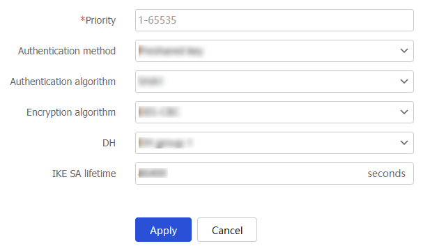
Table-8 Configuration items for IKE proposal creation
Item
Description
Priority
Specify the priority of the IKE proposal.
The peer searches its own IKE proposals for a match. The search starts from the IKE proposal with the highest priority and proceeds in descending order of priority until a match is found. The matching IKE proposals are used to establish the IKE SA. If all user-defined IKE proposals are found mismatching, the two peers use their default IKE proposals to establish the IKE SA.
Authentication method
Specify the authentication method for the IKE proposal. Options include:
Preshared key —Specify the preshared key authentication method.RSA digital signature —Specify the RSA digital signature authentication method.DSA digital signature —Specify the DSA digital signature authentication method.RSA digital envelope —Specify the RSA digital envelope authentication method.SM2 digital envelope —Specify the SM2 digital envelope authentication method.
Authentication algorithm
Specify the authentication algorithm for the IKE proposal. Options include:
MD5 : Specify the HMAC-MD5 algorithm.SHA1 : Specify the HMAC-SHA1 algorithm.SHA256 : Specify the HMAC-SHA256 algorithm.SHA384 : Specify the HMAC-SHA384 algorithm.SHA512 : Specify the HMAC-SHA512 algorithm.SM3 : Specify the HMAC-SM3 algorithm.
Encryption algorithm
Specify the encryption algorithm for the IKE proposal. Options include:
3DES-CBC —Specify the 3DES algorithm in CBC mode, which uses a 168-bit key for encryption.AES-CBC-128 —Specify the AES algorithm in CBC mode, which uses a 128-bit key for encryption.AES-CBC-192 —Specify the AES algorithm in CBC mode, which uses a 192-bit key for encryption.AES-CBC-256 —Specify the AES algorithm in CBC mode, which uses a 256-bit key for encryption.DES-CBC —Specify the DES algorithm in CBC mode, which uses a 56-bit key for encryption.SM1-CBC-128 —Specify the SM1 algorithm in CBC mode, which uses a 128-bit key for encryption.SM4-CBC —Specify the SM4 algorithm in CBC mode as the encryption algorithm, which uses a 128-bit key.
DH
Specify the DH group to be used for key negotiation in IKE phase 1. Options include:
DH group 1 —Use the 768-bit Diffie-Hellman group.DH group 2 —Use the 1024-bit Diffie-Hellman group.DH group 5 —Use the 1536-bit Diffie-Hellman group.DH group 14 —Use the 2048-bit Diffie-Hellman group.DH group 1 9 —Use the 256-bit ECP Diffie-Hellman group.DH group 20 —Use the 384-bit ECP Diffie-Hellman group.DH group 24 —Use the 2048-bit Diffie-Hellman group with the 256-bit prime order subgroup.
IKE SA lifetime
Specify the IKE SA lifetime for the IKE proposal.
Click
OK .
Manage IPsec tunnels
On the IPsec tunnels page, you can view IPsec tunnel information, delete specific tunnels, or delete all tunnels.
Click the
Network tab.Select
VPN >IPsec >IPsec Tunnels .To delete all tunnels, click
Delete all .Figure-13 Deleting all tunnels

To delete a tunnel with a specific remote address, click
Delete tunnel by remote address . On the page that opens, configure the following parameters:Figure-14
Delete tunnel by remote address 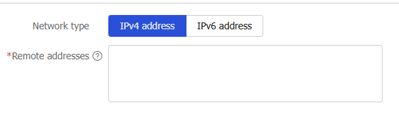
Table-9 Configuration items for basic IPsec settings
Item
Description
Network type
Type of the remote IP address. Options are
IPv4 address andIPv6 address .Remote address
Specify the remote address of the IPsec tunnel.
Click
Apply .
Configure advanced settings
Configure advanced IKE settings
Click the
Network tab.Select
VPN >IPsec >Advanced Settings .In the
IKE area, configure related parameters.Figure-15 Configuring advanced IKE settings
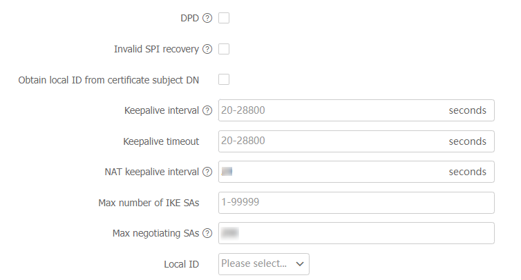
Table-10 Configuration items for advanced IKE settings
Item
Description
DPD
Specify whether to enable DPD.
DPD detects if the IKE peer on the remote device is dead.
DPD mode
Specify the DPD mode. Options include:
O n-demand DPD —Triggers DPD on demand.P eriodic DPD —Triggers DPD at regular intervals.
DPD triggering interval
Specify the DPD triggering interval.
In on-demand DPD mode, the device triggers DPD if it has IPsec traffic to send and has not received any IPsec packets from the peer for the specified interval.
In periodic DPD mode, the device triggers DPD at the specified interval.
DPD retry interval
Specify the DPD retry interval.
Invalid SPI recovery
Specify whether to enable invalid SPI recovery.
An SPI uniquely identifies an SA. When an IPsec peer receives a data packet for which it cannot find an SA, an invalid SPI is encountered. The invalid SPI recovery feature enables the receiving peer to set up an IKE SA with the originator so that an SPI invalid notification can be sent. Upon receiving the notification, the originating peer deletes the IPsec SA that has the invalid SPI. If the originator has data to send, new SAs will be set up. Generally, disable the invalid SPI recovery feature as a best practice.
Obtain local ID from certificate subject DN
Specify whether to obtain local ID from certificate subject DN.
If this feature is selected, the device uses identity information obtained from the local certificate to perform digital signature authentication.
Keepalive interval
Specify the interval at which IKE sends keepalive packets to the peer.
Keepalive timeout
Specify the IKE SA keepalive timeout time during which the local device waits for keepalive packets sent from the peer.
NAT keepalive interval
Specify the NAT keepalive interval.
This feature takes effect only for a device that resides in the private network behind a NAT gateway. The device behind the NAT gateway needs to send NAT keepalives to its peer to keep the NAT session alive, so that the peer can access the device. The NAT keepalive interval must be shorter than the NAT session lifetime.
Max number of IKE SAs
Set the maximum number of established IKE SAs allowed.
Max negotiating SAs
Set the maximum number of half-open IKE SAs and IPsec SAs.
As a best practice, set the value according to the device's performance to make full use of the device's processing capability.
Local ID
Specify the local ID to identify the device to its peer during IKE negotiation. Options include:
NONE —If the local ID is not configured, the global identity configured by executing theike identity command in system view is used as the local ID.IPv4 address —Use the IPv4 address as the local ID.IPv6 address —Use the IPv6 address as the local ID.FQDN —Use the FQDN name as the local ID.User-FDQN —Use the user FQDN name as the local ID.DN —Use the DN in the digital signature as the local ID.
Configure advanced IPsec settings
Go to the
IPsec area.Configure related parameters.
Figure-16 Configuring advanced IPsec settings
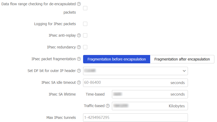
Table-11 Configuration items for advanced IPsec settings
Item
Description
Data flow range checking for de-encapsulated packets
Specify whether to enable ACL checking for de-encapsulated IPsec packets.
With this feature enabled, all packets that fail the checking are discarded, improving the network security.
Logging for IPsec packets
Specify whether to enable logging for IPsec packets.
With this feature enabled, the device outputs a log when an IPsec packet is discarded.
IPsec anti-replay
Specify whether to enable IPsec anti-replay.
With this feature enabled, the device drops replayed packets without wasting resources to de-encapsulate the packets.
Anti-replay window size
Set the size of the anti-replay window.
IPsec redundancy
Specify whether to enable IPsec redundancy.
This feature ensures uninterrupted IPsec traffic forwarding and anti-replay protection during an active/standby switchover.
IPsec packet fragmentation
Specify packet fragmentation before or after IPsec encapsulation. Options include:
F ragmentation before encapsulation —The device predetermines the encapsulated packet size before the actual encapsulation. If the encapsulated packet size exceeds the MTU of the output interface, the device fragments the packets before encapsulation. If a packet's DF bit is set, the device drops the packet and sends an ICMP error message.F ragmentation after encapsulation —The device directly encapsulates the packets and fragments the encapsulated packets in subsequent service modules.
Set DF bit for outer IP header
Specify the DF bit for the outer IP header of IPsec packets on all interfaces. Options include:
CLEAR —Clears the DF bit in the outer IP header. IPsec packets can be fragmented.COPY —Copies the DF bit setting of the original IP header to the outer IP header.SET —Sets the DF bit in the outer IP header. IPsec packets cannot be fragmented.
IPsec SA idle timeout
Specify the global IPsec SA idle timeout.
IPsec SA lifetime
Specify the IPsec SA lifetime.
An IPsec SA expires when the time-based or traffic-based lifetime is reached, whichever comes first.
Time-based
Specify how long the SA can exist after it is created.
Traffic-based
Specify the maximum traffic that the SA can process.
Max IPsec tunnels
Set the maximum number of IPsec tunnels.
To maximize concurrent performance of IPsec when memory is sufficient, increase the maximum number of IPsec tunnels. To ensure service availability when memory is insufficient, decrease the maximum number of IPsec tunnels.
Configure advanced quantum encryption settings
Go to the
Quantum Encryption area.Configure related parameters.
Figure-17 Configuring advanced quantum encryption settings
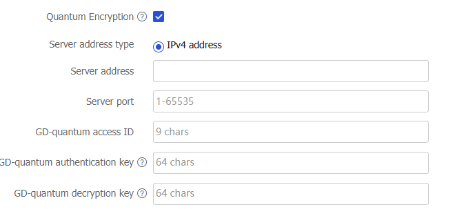
Table-12 Configuration items for advanced quantum key settings
Item
Description
Quantum Encryption
After quantum encryption is enabled, IPsec will use the symmetric keys provided by the quantum server to encrypt the data protected by IPsec, enhancing the security provided by IPsec.
Server address
IP address of the GD-quantum server.
Server port
Port number of the GD-quantum server.
GD-quantum access ID
This access ID is assigned by the GD-quantum server. Each device has only one access ID and the ID is unique across the network. Contact the administrator of the GD-quantum server to obtain the access ID.
GD-quantum authentication key
This key is used to authenticate the device identity on the GD-quantum server, and corresponds one-to-one with the device's GD-quantum access ID. Contact the administrator of the GD-quantum server to obtain the authentication key.
GD-quantum decryption key
Decryption key for GD-quantum keys. Contact the administrator of the GD-quantum server to obtain the decryption key.
Click
Apply .