Hot backup
This help contains the following topics:
Introduction
Hot backup is a device-level HA solution.
It relies on Remote Backup Management (RBM) to enable two devices to back up each other dynamically to ensure user service continuity upon failure of one of the devices or network links.
The hot backup system works with RBM to manage multiple VRRP groups or adjust the link costs for routing protocols on two member devices to ensure that the devices have consistent roles and states. The hot backup system can synchronize important configuration and service entries between the devices to ensure service continuity. Two devices must have the same software and hardware environments to join the hot backup system.
Basic concepts in hot backup configuration
Basic concepts in hot backup configuration are as follows:
Primary and secondary roles —Control the direction of configuration synchronization between devices. The hot backup roles are assigned to the two devices in a hot backup system, respectively. The primary device synchronizes its configuration to the secondary device, and the configuration on the secondary device is overwritten. You can configure the service modules for which hot backup synchronizes configuration only on the primary device.Active and standby states —Determine which device forwards and processes traffic in the data plane. The active device forwards traffic of services and backs up service entries to the standby device in real time. When the active device fails, the standby device takes over the active role to ensure service continuity.VRRP active and standby groups —Associate the hot backup system with VRRP for the hot backup system to centrally manage the status of multiple VRRP groups.Hot backup channels —Transmit status information, important configuration, and service entries between the hot backup members.Hot backup modes —Include active/standby mode, mirroring mode, and dual-active mode. In active/standby mode, the active device processes all services. In mirroring mode, the interfaces on the two devices (except the management interface and RBM channel interface) use the same IP address, and only the active device processes services. In dual-active mode, both devices process services to increase the capability of the hot backup system and load share traffic.Hot backup packets —Transmitted through TCP over the hot backup channel between the hot backup members.Mirroring mode management interface —In RBM mirroring mode, interface configurations on the primary device (except the management interface and RBM channel interface) are synchronized to the secondary device. Interfaces connected to the network management device and log host have use the same IP addresses on both devices. Only the primary device can establish connections with the network management device and log host. The secondary cannot establish the connections. To avoid this issue, you can configure the mirroring mode management interface, whose configurations will not be synchronized.
Operating modes of the hot backup system
The hot backup system supports the active/standby, mirroring, and dual-active modes.
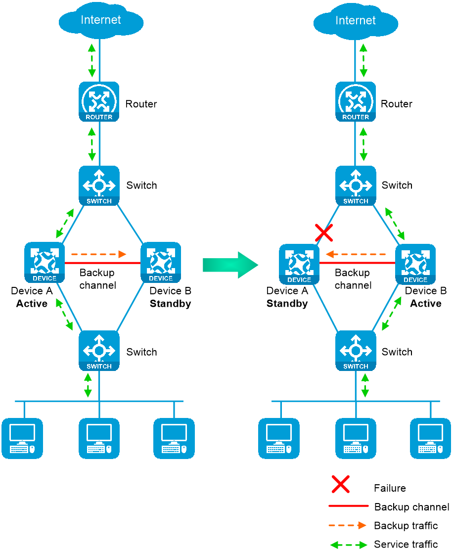
Active/standby mode
In active/standby mode, one device is active to process services, and the other device stands by, as shown in Figure-1. When an interface or link on the active device fails or when the active device fails, the standby device becomes active to process services.
Figure-1 Active/standby mode of the hot backup system
Mirroring mode
The mirroring mode is a special active/standby mode, and its deployment is the same as that for the active/standby mode. In mirroring mode, the interfaces on the two devices (except the management interface and RBM channel interface) use the same IP address, and typically the active device processes services, and the other device stands by. When an interface or link on the active device fails or when the active device fails, the standby device becomes active to process services.
This networking environment requires associating hot backup with Track. Without hot backup and Track collaboration, active/standby switchover cannot be performed.
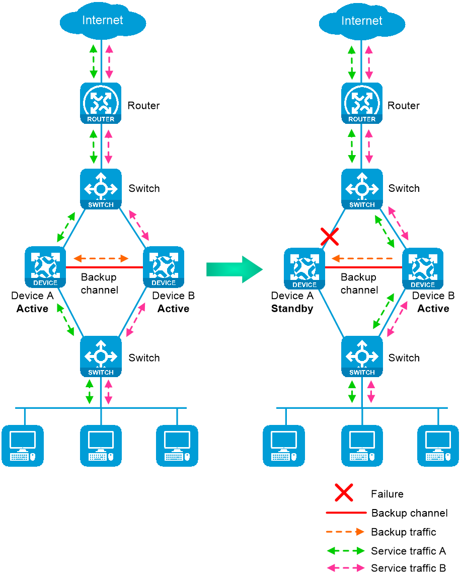
Dual-active mode
In dual-active mode, both devices process services to increase capability of the hot backup system, as shown in
Figure-2 Dual-active mode of the hot backup system
Hot backup channels
Overview
The hot backup members transmit hot backup system status, important configuration, and service entries over the following channels:
Control channel —Transmits data by using packets, including hot backup system keepalive packets, status packets, configuration consistency check packets, backup packets for service entries, data packets that require transparent transmission, and configuration synchronization packets.Data channel —Transmits only backup packets and packets that require transparent transmission. The data channel supports transmitting packets at Layer 2 and Layer 3.
Establishment and keepalive mechanism of the control channel
The control channel uses the keepalive mechanism of TCP for reachability detection. The control channel is established through TCP. In the hot backup system, the device with the higher IP address acts as the server, and the other device acts as the client to initiate the TCP connection.
Each member device periodically sends hot backup keepalive packets to the hot backup peer over the hot backup control channel. If a device has not received any responses from the peer when the maximum number of hot backup keepalive attempts is reached, the hot backup control channel is disconnected.
Service entry backup
Overview
The hot backup system backs up the service entries generated on the active device to the standby device to prevent service interruption when an active/standby switchover occurs.
Security devices like firewalls generate a session entry for each dynamic connection. In the hot backup system, only the active device processes traffic and generates session entries. To ensure service continuity, the active device backs up its session entries to the standby device in real time. After an active/standby switchover, the new active device can forward the packets of the existing services based on the session entries without interruption.
Supported services
The hot backup system can perform hot backup for the following service entries:
Entries for IPsec tunnels.
Domain name resolution entries.
Session entries.
Session relation entries.
NAT port blocks.
AFT port blocks.
Entries generated by security service modules.
Support for these entries depends on the device model.
Configuration backup
Overview
The hot backup system backs up important configuration from the primary device to the secondary device to prevent service interruption when an active/standby switchover occurs. The configuration on the secondary device is overwritten. The unidirectional backup mechanism avoids configuration conflicts, especially in dual-active mode. As a best practice to ensure correct operation of the hot backup system, enable configuration backup on the primary device.
Backup type
The hot backup system supports both automatic backup and manual backup.
Supported services
The hot backup system in active/standby and dual-active modes can perform configuration backup for the following services:
Resources: VPN instance, ACL, object group, time range, security zone, session management, APR, AAA, domain name resolution.
DPI: Application layer inspection engine, IPS, URL filter, data filter, file filter, anti-virus, data analysis center, WAF, APT defense.
Policies: Security policy, ASPF, attack detection and prevention, connection limit, NAT, AFT, load balancing, global load balancing, bandwidth management, application auditing and management, shared network access management, proxy policy.
Logs: Fast log output, flow log.
SSL VPN, IPsec.
Password control.
VLAN.
Information center.
Cloud connection.
IPoE.
In addition to the previous services, the hot backup system in mirroring mode can perform configuration backup for the following services: Device login, configuration file management, device management, MAC address table configuration, VLAN termination, Layer 2 forwarding, ARP, IP addressing, DHCP, IP forwarding basics, fast forwarding, multi-CPU packet load sharing, IP performance optimization, IPv6 basics DHCPv6, IPv6 fast forwarding, tunneling, GRE, IP routing basics, static routing, RIP, OSPF, BGP, PBR, IPv6 static routing, RIPng, OSPFv3, IPv6 PBR, routing policies, MPLS L3VPN, QoS, keychain, PKI, SSH, ARP attack protection, MFF, BFD, NTP, SNMP, EVI, VXLAN.
Support for these services depends on the device model.
Configuration consistency check
The hot backup system verifies configuration consistency between the hot backup members by using configuration consistency check packets. If a device detects configuration inconsistency, it generates a log for you to manually synchronize configuration.
Hot backup system in collaboration with VRRP
Overview
You can use the hot backup system and VRRP in combination to control master/backup switchover for device role consistency (master or backup) in multiple VRRP groups. This ensures that both inbound and outbound traffic can be switched to the new master for symmetric forwarding upon device failure.
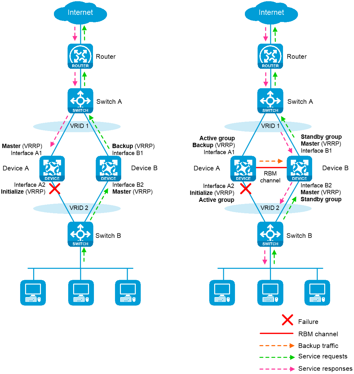
Figure-3 illustrates VRRP association with the hot backup system in active/standby mode.
As shown in the left, VRRP cannot ensure symmetric forwarding upon failure on a device, which causes traffic interruption.
As shown in the right, after the hot backup control channel is established, the hot backup system determines the roles of the devices in all VRRP groups. The master election mechanism of VRRP no longer takes effect. If the hot backup control channel is disconnected, the master election mechanism of VRRP takes effect again.
Figure-3 Hot backup system in collaboration with VRRP
VRRP active/standby group
The hot backup system is associated with VRRP by VRRP active and standby groups.
A VRRP active/standby group can be in master or backup state, which determines the state of devices in the associated VRRP groups. For example, if a VRRP active group is in master state, all devices in the associated VRRP groups are masters.
The initial state of a VRRP active/standby group is as follows:
Active/Standby mode —On the primary device, the initial state is master for the VRRP active and standby groups. On the secondary device, the initial state is backup for the VRRP active and standby groups.Dual-active mode —The state of a VRRP active/standby group is not affected by the hot backup roles. The initial state is master for the VRRP active group and is backup for the VRRP standby group.
VRRP master election in the hot backup system
After the hot backup system is associated with VRRP, the hot backup system determines the roles of the devices in the VRRP groups. As shown in Figure-3, Device A is the master in VRRP group 1 and VRRP group 2, and Device B is the backup in VRRP group 1 and VRRP group 2. When Interface A2 on Device A fails, the following events occur:
The hot backup system receives an interface failure event and sends the status change information of the VRRP active and standby groups to Device B.
Device B sets its role to master in the VRRP standby group and then becomes the master in VRRP group 1 and VRRP group 2.
Device B sends a response to Device A after the master/backup switchover.
Device A sets its role to backup in the VRRP active group and then becomes the backup in VRRP group 1 and VRRP group 2.
When Interface A2 recovers, the hot backup system performs another master/backup switchover following the same procedure. Traffic is switched back to Device A after the switchover.
ARP and MAC learning in VRRP
When the members of a VRRP group receive an ARP request for the group's virtual IP address, the master replies with the group's virtual MAC address. This allows the upstream and downstream Layer 2 devices and hosts to learn the virtual MAC address.
Hot backup in collaboration with virtual IP addresses
Overview
In a cloud scenario, each tenant is assigned an independent IP network. Hot backup in collaboration with VRRP requires three IP addresses for each VRRP group, which might lead to IP address insufficiency. To resolve this issue, use hot backup in collaboration with virtual IP addresses.
For hot backup to collaborate with virtual IP addresses, assign a virtual IP address to the same numbered service interfaces on the hot backup member devices. The virtual address will be associated with and managed by RBM. The primary device uses the virtual IP address and virtual MAC address of the local service interface to respond to ARP requests. The secondary device does not respond to ARP requests. In this way, all upstream and downstream traffic is directed to the primary device for processing.
Mechanism
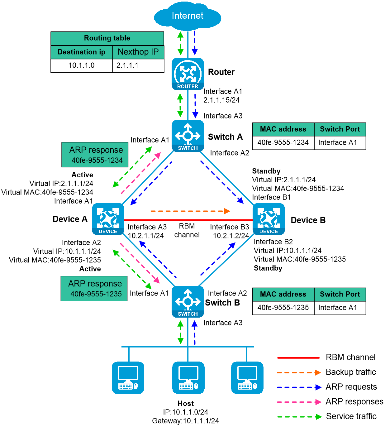
As shown in Figure-4, traffic is sent from the internal network to the external network as follows:
The host broadcasts an ARP request to obtain the MAC address of the gateway at virtual IP address 10.1.1.1.
Device A and Device B receive the ARP request, and only Device A, the primary device, replies to the host with the virtual MAC address of its local service interface.
Switch B learns the virtual MAC address of the gateway.
The host receives the ARP reply, encapsulates service quests with the virtual MAC address, and sends the service requests to Device A.
Service responses are sent to the host by following the typical forwarding process.
Figure-4 Hot backup in collaboration with virtual IP addresses
Hot backup system in collaboration with routing protocols
Overview
You can configure hot backup to enable the routing protocols on the standby device to advertise modified link cost. The feature ensures that both inbound and outbound traffic can be switched to the new active device for symmetric forwarding.
To use the hot backup system with routing protocols, you must use track entries to monitor the status of uplink and downlink interfaces for the hot backup system to perform an active/standby switchover when link or interface failure occurs.
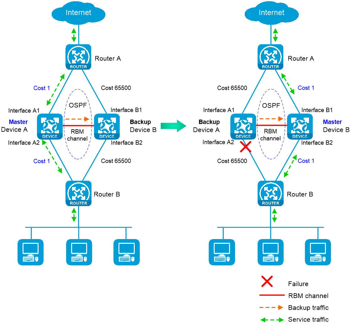
The following information uses OSPF on the hot backup system in active/standby mode to describe how the hot backup system collaborates with dynamic routing protocols:
As shown in Figure-5, when both Device A (active) and Device B (standby) are operating correctly, Device A advertises the original link cost 1, and Device B advertises the link cost 65500, which has been adjusted by the hot backup system. As a result, Device A forwards all traffic that traverses the hot backup system.
As shown in Figure-5, when downlink Interface A2 of Device A fails, Device A and Device B switch their states. Then, Device B (active) advertises the original link cost 1, and Device A (standby) advertises the adjusted link cost 65500. As a result, Device B forwards all traffic that traverses the hot backup system.
Figure-5 Hot backup system in collaboration with routing protocols
Mechanism
The hot backup system adjusts the link costs advertised by dynamic routing protocols by using one of the following methods:
Replacing the original link cost with the absolute link cost that you configure.
Adding an incremental value to the original link cost.
The link cost changes do not affect the hot backup roles of devices, and you must configure the same link cost adjustment settings on the hot backup member devices.
Transparent in-path deployment of the hot backup system
When you use this networking scheme, you can configure the hot backup system to monitor interfaces or VLANs to enable collaboration between uplink and downlink interfaces. The monitoring configuration ensures that a group of interfaces have the same status, and uplink and downlink traffic can be switched simultaneously between the member devices.
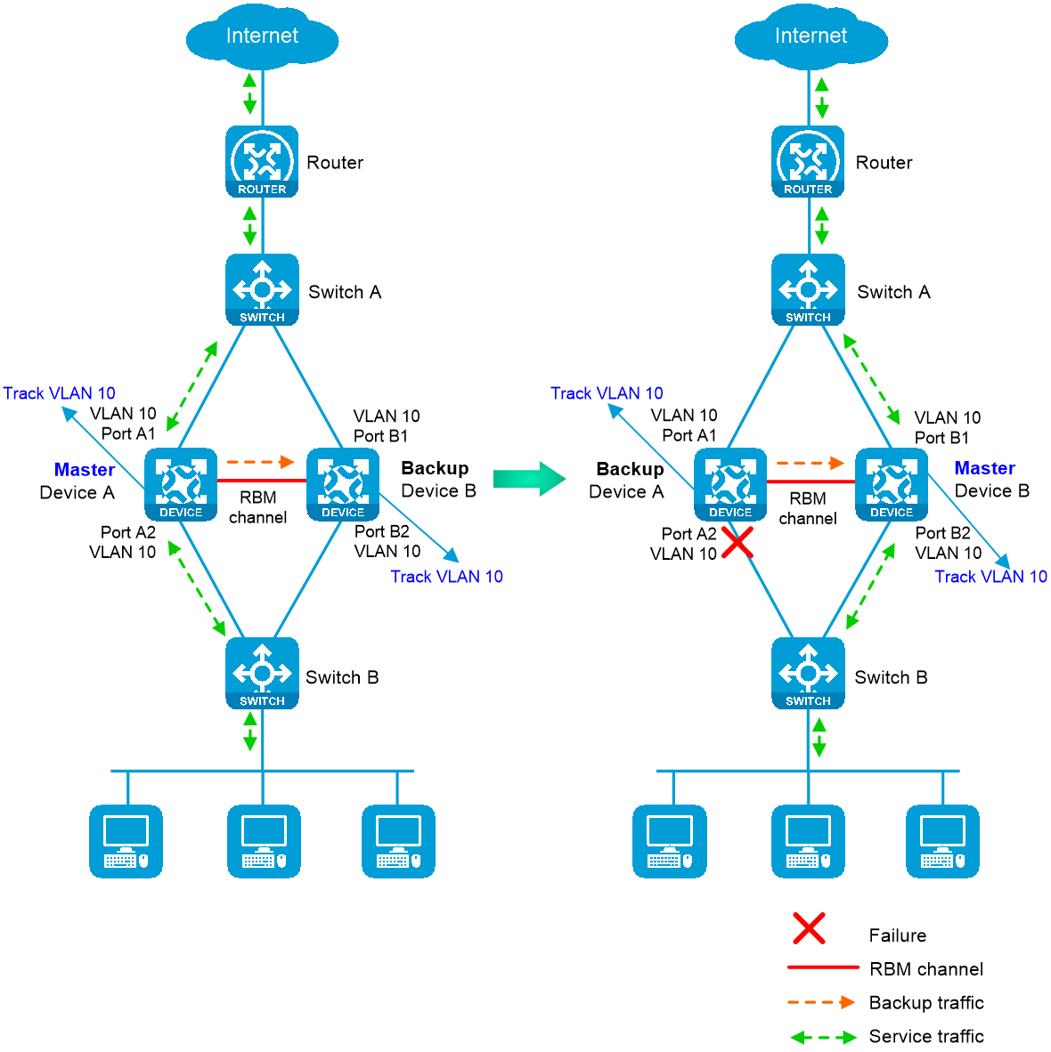
The following information uses VLAN monitoring as an example to describe how interfaces collaborate:
As shown in Figure-6, when both Device A (active) and Device B (standby) are operating correctly, tracked VLAN 10 is in active state on Device A and in inactive state on Device B. As a result, Device A forwards all traffic that traverses the hot backup system.
As shown in Figure-6, when downlink Port A2 of Device A fails, Device A and Device B switch their states. Then, the hot backup system places VLAN 10 in inactive state on Device A (standby) and in active state on Device B (active). As a result, Device B forwards all traffic that traverses the hot backup system.
Figure-6 Transparent in-path deployment of the hot backup system
vSystem support information
Support of non-default vSystems for this feature depends on the device model. This feature is available on the Web interface only if it is supported.
Restrictions and guidelines
Hardware environment consistency
Before you configure hot backup, verify that the following hardware settings are the same on the devices to be assigned to the hot backup system:
Device model.
Location, number, and type of interface modules.
Number and type of management interfaces, service interfaces, and interfaces for setting up the RBM channels. Do not use one interface for multiple purposes.
Location, number, and type of disks. A device not with disks installed has small log storage and do not support some types of logs or reports.
Software environment consistency
Before you configure hot backup, verify that the following software settings are the same on the devices to be assigned to a hot backup system:
Software environment and version, including boot packages, system packages, feature packages, and patches.
Licensed signature libraries and features, such as signature library types, signature library version, validation time, and number of licensed resources.
Resource files, such as public keys and ISP address database files.
Interface numbers.
System time.
Type, speed, and number of the interfaces for setting up the RBM channels. As a best practice, use aggregate interfaces.
Aggregate interface numbers and aggregation member port numbers.
Security zone configuration on the interfaces at the same location.
Multi-CPU packet distribution policy.
Hot backup restrictions
You can use hot backup only with VRRP standard mode. VRRP load sharing mode does not support hot backup.
You can configure the hot backup system to monitor track entries, VLANs, or interfaces, but you cannot configure VLAN monitoring in combination with interface monitoring. When you configure the hot backup system to monitor both track entries and interfaces, make sure the track entries are not associated with the monitored interfaces. When you configure both interface monitoring and VRRP association, make sure the interfaces used by the features do not overlap.
The IP address of the data channel interface must be different from the peer interface's IP address.
You can configure both IPv4 and IPv6 addresses for the data channel interface. The device will select a data channel interface IP address based on the local IP address type of the control channel to establish a connection with the peer.
Some hot backup features can only be configured at CLI and are not supported on the Web interface. Support for the features depends on the Web interface of the device.
Mirroring mode restrictions
Create a mirroring mode hot backup system by using two devices in their initial state (without hot backup mode configured). If the devices are in operation, do not switch directly from non-mirroring to mirroring mode. Instead, reset them to their initial state before switching to avoid potential service exceptions.
For hot backup in mirroring mode, interfaces with the same number on both devices use the same IP address, except for the mirroring mode management interface and RBM channel interface.
For IPv6 hot backup in mirroring mode, interfaces with the same number on both devices use the same IPv6 address and IPv6 link-local address. Manually configure the IPv6 link-local address and do not use automatically generated address to avoid inconsistencies.
In mirroring mode, hot backup cannot collaborate with VRRP or virtual addresses. If VRRP or virtual addresses are configured on a device, you cannot enable the mirroring mode. You cannot configure VRRP or virtual addresses on the device after enabling the mirroring mode.
If mirroring mode is enabled, the configurations that can be backed up between the two devices increase. For example, interface IP address configuration commands, which are not backed up in non-mirroring mode, will be backed up after you enable the mirroring mode. For information about the service module configuration synchronization supported in mirroring mode, see "
With mirroring mode enabled, the device can adjust the state of service interfaces based on their running roles. Service interfaces on the primary device receive and send packets, while those on the standby device can only send and receive Layer 3 and lower-layer packets, such as LLDP and LACP packets.
Only static routes are supported between the device and upstream/downstream devices. Dynamic routing protocols or RIR are not supported. For example, in mirroring mode, the standby device does not send or receive routing protocol packets, so it cannot establish a dynamic routing neighbor relationship with upstream/downstream devices. During an active/standby switchover, the new primary device must renegotiate routing information, resulting in longer service interruptions. Therefore, mirroring mode hot backup is not supported when the service interfaces of both devices operate at Layer 3, connect to routers in the uplink or downlink direction, and run dynamic routing protocols with those routers.
If no control channel or device management role is configured, you cannot configure RBM to operate in mirroring mode.
Configure hot backup
Analysis
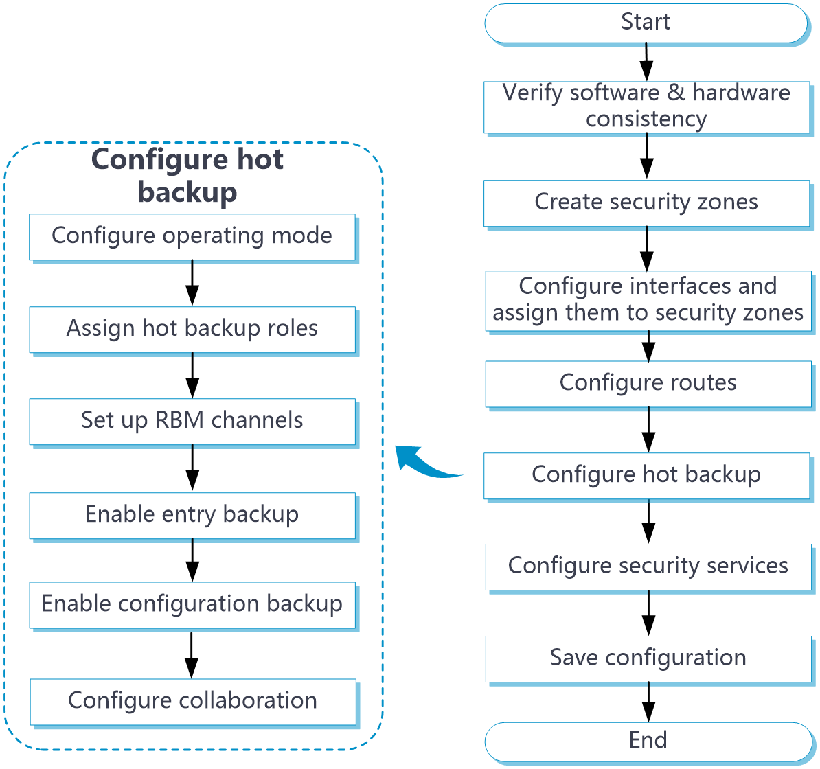
Hot backup system configuration flow
Figure-7 Hot backup system configuration flow chart
Prerequisites
Complete the following tasks before you configure this feature:
Assign IP addresses to interfaces on the
Network >Interface Configuration >Interfaces page.Configure routes on the
Network >Routing page. Make sure the routes are available.Create security zones on the
Network >Security Zones page.Add interfaces to security zones. You can add interfaces to a security zone on the
Security Zones page or select a security zone for an interface on theInterfaces page.Configure security policies to permit the target traffic on the
Policies >Security Policies page.
Configure hot backup in active/standby mode
In active/standby mode, only the active device processes services. Upon an interface or link failure of the active device or a failure of the active device, the standby device immediately takes over to process services.
Configure hot backup
Click the
System tab.From the navigation pane, select
High Availability >HA Group .The
Mode page opens.Click
Configure .On the
Configure Hot Backup Configure hot backup.
Figure-8 Configuring hot backup
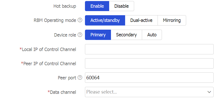

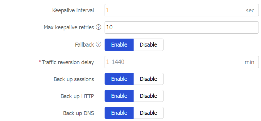

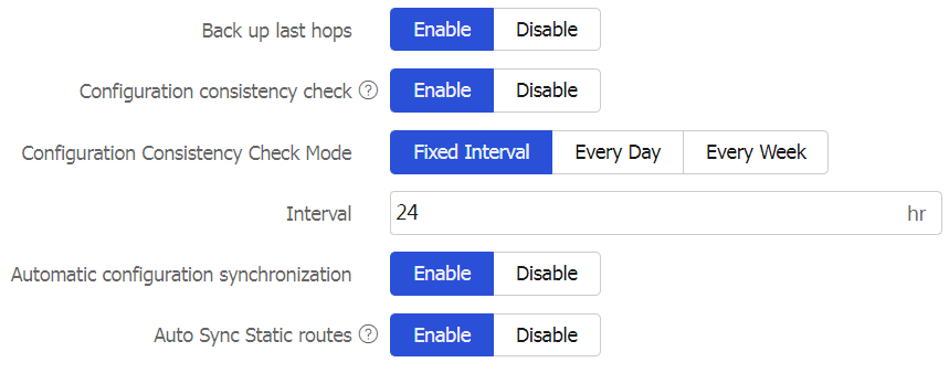
Table-1 Hot backup system parameters
Parameter
Description
Hot backup
Set the status of the hot backup feature.
Device role
Assign hot backup roles to the member devices in the hot backup system. In a hot backup system, the hot backup role of one device must be primary, and the other secondary. To use automatic hot backup role assignment, you must enable automatic hot backup role assignment on both devices.
The hot backup system supports both manual and auto modes for device role selection.
Primary/Secondary —Manually assign the hot backup roles, primary and secondary, to the member devices. The hot backup role of a device does not change unless you manually change it on the hot backup configuration page. Use this mode if the member devices have dedicated management interfaces. This mode is available in both active/standby and dual-active modes. This option applies to only the hot backup active/standby and dual-active modes. You cannot specify this option in mirroring hot backup mode.Auto —Assign the hot backup roles to the member devices according to their operating mode and allow the member devices to switch their hot backup roles. For each member device, the hot backup role is consistent with the operating state. The active device is the primary device, and the standby device is the secondary device. Use this mode if the member devices use service interfaces as management interfaces. This mode is available only in active/standby or mirroring mode. In this mode, you can view the current hot backup role of the device by checking the running management role parameter on the host backup page.
Local IP of Control Channel
Enter a local IP address to set up the control channel. The server end listens for TCP connection requests at this IP address. You can enter an IPv4 or IPv6 address, but not both.
The local IP address cannot be identical to the peer IP address.
Peer IP of Control Channel
Enter the peer IP address used for setting up the control channel. You can enter an IPv4 or IPv6 address, but not both.
The peer IP address cannot be identical to the local IP address.
Peer port
Enter the port number for the control channel. The hot backup member devices must have the same port number.
Management Interface
Configure the mirroring mode management interface for connecting to the gateway device or log host. Configurations of this interface will not be synchronized.
This configuration is supported only in mirroring mode.
Data channel
Select an interface to set up the data channel that transmits backup packets and the packets that require transparent transmission.
Data Channel Message Transmission Mode
A data channel supports the following packet transmission modes:
Layer 2 —The data channel supports transmitting packets across Layer 2 switches, but does not support transmitting packets across Layer 3 devices.Layer 3 —The data channel supports transmitting packets across both Layer 2 and Layer 3 devices. In networking environments where Layer 2 channels cannot be used as data channels to transmit packets, you can specify the hot backup data channel packet transmission mode as Layer 3, for example, in RBM networking with virtualized devices.
Support for this configuration is subject to the actual page display.
Keepalive interval
Set the interval for the device to periodically send keepalive packets to the peer device.
Max keepalive retries
Set the maximum number of keepalive retries. If this limit is reached before the device receives any responses from the peer device, the device disconnects the hot backup channels to the peer device.
Fallback
Enable this feature for traffic to be switched back to the original active device upon its recovery.
Traffic reversion delay
Set the delay that the hot backup members must wait before a switchback. This delay allows the devices to finish service entry backup to prevent traffic loss.
Back up sessions
Set the status of session backup. If you enable this feature, the active device backs up service module entries to the standby device in real time. When the active device fails, the standby device can take over without service interruption.
Back up HTTP
Back up DNS
Back up the session entries created for received DNS and HTTP protocol packets.
The hot backup system backs up the sessions created for other application protocols as long as service entry backup is enabled.
Enable HTTP and DNS backup if asymmetric-path traffic traverses the hot backup system. HTTP and DNS backup ensures that a flow and its return traffic are processed correctly on the hot backup members.
If hot backup active/standby or mirroring mode is used or only symmetric-path traffic traverses the hot backup system, disabling HTTP and DNS backup can improve performance of the hot backup members at the expense of delayed data synchronization. When you disable HTTP and DNS backup, make sure you are fully aware of the impact on the network. A device removes a DNS or HTTP connection if packet exchange is inactive. When a switchover interrupts a connection, the DNS or HTTP client re-initiates the connection immediately, which has little impact on user services.
Back up AFT port blocks
Back up AFT port blocks in real time.
Back up last hops
Back up lost hop information if last hop holding is enabled on interfaces and globally on the primary device. When an interface enabled with this feature receives the first IP packet of a forward flow, the primary device saves the last hop information and backs up the information to the secondary device. When packets of the return flow arrive at the primary or secondary device, the device forwards those packets according to the last hop information. Support for this feature varies by device model.
Configuration consistency check
Set the status of the configuration consistency check feature.
Configuration Consistency Check Mode
Set the interval of configuration consistency check:
Fixed Interval —Perform the check at a fixed interval.Every Day —Perform the check at a fixed time every day.Every Week —Perform the check at a fixed time every week.
Automatic configuration synchronization
Set the status of the automatic configuration synchronization feature.
After you enable this feature, the primary device backs up its configuration to the secondary device in bulk. When the configuration on the primary device changes, the primary device backs up the new configuration to the secondary device in real time.
If the amount of configuration to be synchronized is large, bulk synchronization might take one to two hours. As a best practice to reduce the bulk synchronization duration, enable this feature when you configure the hot backup system.
Auto Sync Static routes
Use this function only in mirroring mode or when hot backup and virtual IP addresses are used in combination to direct traffic. Do not use it in any other scenarios.
Enable the primary device to send static routes to the secondary device during automatic or manual configuration synchronization.
If you enable this function after automatic configuration synchronization is enabled, static routes added afterwards are synchronized automatically. Existing static routes can only be synchronized manually.
If you enable this function and then enable automatic configuration synchronization, all static routes can be synchronized to the secondary device.
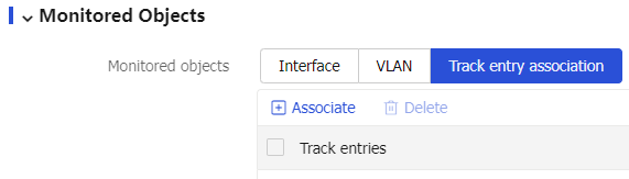
(Optional.) Configure Track settings.
Figure-9 Configuring Track settings
Parameter
Description
Track entry association
Select the track entries to be monitored by the hot backup system. If one of the monitored track entries becomes Negative, the hot backup system performs an active/standby switchover and switches traffic to the new active device to ensure service continuity.
Click
OK .
Configure VRRP collaboration
Associate the hot backup system with VRRP on the VRRP page. For more information about the configuration procedure, see the VRRP help.
Configure hot backup to collaborate with virtual IP addresses
You must associate RBM with Track in the network environment. Without the configuration, active/standby switchover cannot be performed upon uplink or downlink link or interface failures.
Click the
Network tab.From the navigation pane, select
Interface Configuration >Interfaces .Select a service interface to collaborate with hot backup, and then click
Edit .Figure-10 Editing interface settings
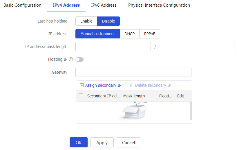
Select
Floating IP on theIPv4 Address orIPv 6 Address tab. The virtual IP address will be associated with and managed by RBM.Figure-11 Floating IP

Configure the hot backup system to collaborate with a routing protocol
You must associate RBM with Track in the network environment. Without the configuration, active/standby switchover cannot be performed upon uplink or downlink link or interface failures.
Click the
System tab.From the navigation pane, select
High Availability >HA Group .The
Mode page opens.Click
Configure .The
Configure Hot Backup Configure routing collaboration parameters.
Figure-12 Configuring routing collaboration parameters
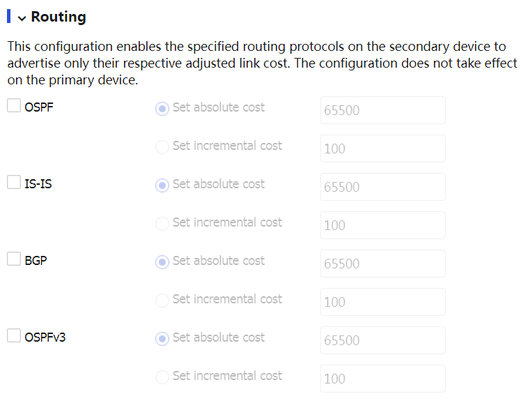
Table-3 Routing collaboration parameters
Parameter
Description
OSPF
Adjust the link costs advertised by OSPF.
IS-IS
Adjust the link costs advertised by IS-IS.
BGP
Adjust the link costs advertised by BGP.
OSPFv3
Adjust the link costs advertised by OSPFv3.
Set absolute cost
Enter an absolute link cost. The hot backup system will use this value to replace the link costs to be advertised.
Set incremental cost
Enter an incremental value. The hot backup system will add this value to the link costs to be advertised.
Click
OK .
Configure transparent in-path deployment
Click the
System tab.From the navigation pane, select
High Availability >HA Group .The
Mode page opens.Select
Active/standby ,Mirroring , orDual-active , and then clickApply .Click
Configure .The
Configure Hot Backup Configure monitoring parameters.
Figure-13 Configuring monitoring parameters
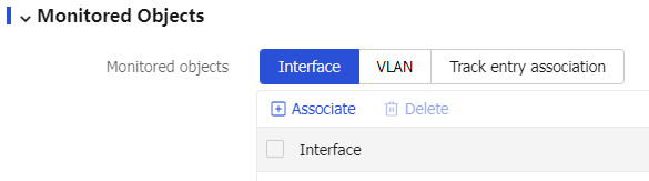
Parameter
Description
Interface
Select the interfaces to be monitored by the hot backup system.
You cannot configure the hot backup system to monitor aggregation member ports.
The hot backup system monitors the status of the monitored interfaces to ensure interface status consistency. A monitored interface can forward traffic only when all monitored interfaces are up.
VLAN
Select the VLANs to be monitored by the hot backup system.
The hot backup system monitors the member ports of a monitored VLAN to ensure member port status consistency. A port in a monitored VLAN can forward traffic only when all ports in the VLAN are up.
You cannot configure the hot backup system to monitor VLAN 1. All access ports belong to VLAN 1 by default. If you configure the hot backup system to monitor VLAN 1, traffic forwarding will be affected on ports in use when an unused port is placed in down state in VLAN 1.
Click
OK .
Configure hot backup in dual-active mode
In dual-active mode, both devices process services to increase the capability of the RBM system and load share traffic. This mode is implemented through mutual backup. Upon a failure of one device, the other device immediately takes over to ensure service continuity.
Configure hot backup
Click the
System tab.From the navigation pane, select
High Availability >HA Group .The
Mode page opens.Click
Configure .On the
Configure Hot Backup Figure-14 Configuring the RBM operating mode
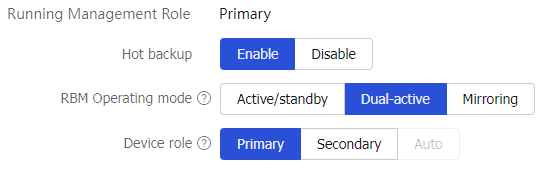
Configure hot backup. For more information, see "Configure hot backup."
(Optional.) Configure Track settings. For more information, see "Configure hot backup."
Click
OK .
Configure VRRP collaboration
Associate the hot backup system with VRRP on the VRRP page. For more information about the configuration procedure, see the VRRP help.
Configure the hot backup system to collaborate with a routing protocol
You must associate RBM with Track in the network environment. Without the configuration, active/standby switchover cannot be performed upon uplink or downlink link or interface failures. For more information about the configuration, see "Configure the hot backup system to collaborate with a routing protocol."
Configure transparent in-path deployment
For more information about the configuration, see "Configure transparent in-path deployment."
Configure hot backup in mirroring mode
The mirroring mode is a special active/standby mode, and its deployment is the same as that for the active/standby mode. In mirroring mode, the interfaces on the two devices (except the mirroring mode management interface and RBM channel interface) use the same IP address, and typically the active device processes services, and the other device stands by. When an interface or link on the active device fails or when the active device fails, the standby device becomes active to process services.
This networking environment requires associating RBM with Track. Without RBM and Track collaboration, active/standby switchover cannot be performed.
Procedures
Click the
System tab.From the navigation pane, select
High Availability >HA Group .The
Mode page opens.Click
Configure .On the
Configure Hot Backup Figure-15 Configuring the RBM operating mode
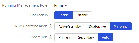
Configure hot backup. For more information, see "Configure hot backup."
(Optional.) Configure Track settings. For more information, see "Configure hot backup."
Click
OK .
Configure advanced hot backup features
Click
Check orSynchronize configuration to check configuration consistency or synchronize configuration on the hot backup page.Figure-16 Manually checking configuration consistency or synchronizing configuration

Table-5 Configuration consistency check and configuration synchronization parameters
Parameter
Description
Check
Perform configuration consistency check manually. If inconsistency is detected, the system generates a log for you to manually synchronize configuration.
Synchronize configuration
Manually synchronize the configuration of the primary device to the secondary device.
Access the hot backup configuration page to switch the states of the devices in the hot backup system. You can trigger an active/standby switchover or place a device in active or standby state to redirect traffic to one device before you perform hardware replacement or software upgrade on the other device. Transient VRRP virtual IP conflicts might occur after you perform this task if VRRP is used with the hot backup system. The conflicts do not affect services. Support for the parameters of this feature depends on the RBM operating mode.
Figure-17 Manually performing active/standby switchover

Table-6 State switchover parameters
Parameter
Description
Switch states
When the active or standby device is not faulty in the hot backup system, use this option to trigger a switchover and switch services to the peer device for processing. This allows administrators to replace components or upgrade software on the active device.
In the active/standby or mirroring network, manually switch the state of the devices in the hot backup system. You can perform this task on the active or standby member device.
Switch peer to active
Place the peer device to active state in dual-active mode for the local device to become the standby device.
Switch peer to standby
Place the peer device to standby state in dual-active mode for the local device to hold its active state.
Reset
Trigger an active/standby device election from the active or standby device.