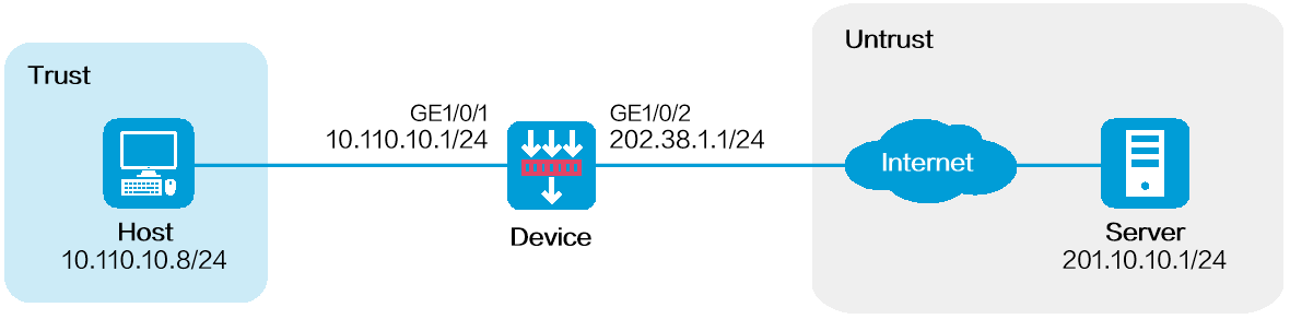
As shown in Figure 1, configure policy-based source address translation to allow the host at 10.110.10.8/24 to access the server at 201.10.10.1/24 on the Internet by using public IP address 202.38.1.100.
This configuration example was created and verified on R9071 of the M9000-AI-E8 device.
Do not configure both policy-based NAT and interface-based NAT.
Assign IP addresses to interfaces and add the interfaces to security zones.
# On the top navigation bar, click Network.
# From the navigation pane, select Interface Configuration > Interfaces.
# Click the Edit icon for GE 1/0/2.
# In the dialog box that opens, configure the interface:
Select the Untrust security zone.
On the IPv4 Address tab, enter the IP address and mask of the interface. In this example, enter 202.38.1.1/24.
Click OK.
# Add GE 1/0/1 to the Trust security zone and set its IP address to 10.110.10.1/24 in the same way you configure GE 1/0/2.
Configure settings for routing.
This example configures a static route. If dynamic routes are required, configure a dynamic routing protocol.
# On the top navigation bar, click Network.
# From the navigation pane, select Routing > Static Routing.
# On the IPv4 Static Routing tab, click Create.
# In the dialog box that opens, configure a static route to permit packets from the device to the server:
Specify the IP address of the server as the destination IP. In this example, the address is 201.10.10.1.
Enter the mask length. In this example, enter 24.
Specify the next-hop address as 202.38.1.2.
Click OK.
Configure a security policy.
# On the top navigation bar, click Policies.
# From the navigation pane, select Security Policies > Security Policies.
# Click Create and click Create a policy.
# In the dialog box that opens, configure policy parameters as follows:
Enter a policy name. In this example, the name is Secpolicy.
Select the source zone. In this example, the source zone is Trust.
Select the destination zone. In this example, the destination zone is Untrust.
Select IPv4 as the type.
Select Permit as the action.
Specify the IP address of the host as the source IPv4 address. In this example, the address is 10.110.10.8.
Specify the IP address of the server as the destination IPv4 address. In this example, the address is 201.10.10.1.
Click OK.
Create a policy-based NAT rule.
# On the top navigation bar, click Policies.
# From the navigation pane, select Policy-based NAT.
# Click Create.
# Create a policy-based NAT rule, as shown in Figure 2.
Figure 2 Creating a policy-based NAT rule
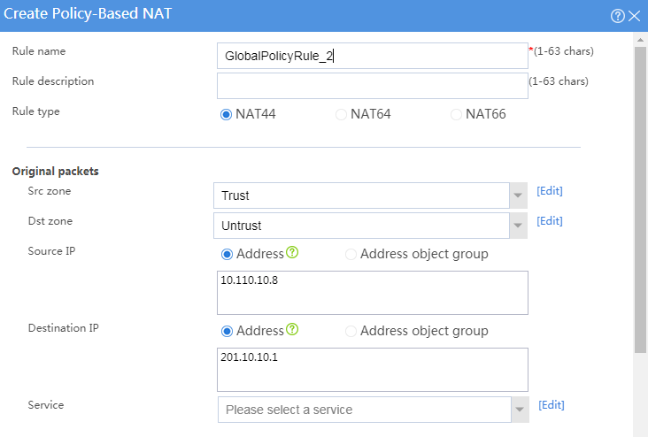
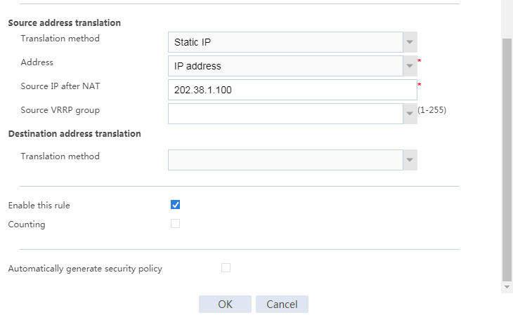
# Click OK.
C:\Users\abc>ping 201.10.10.1
Pinging host.com [201.10.10.1] with 32 bytes of data:
Reply from 201.10.10.1: bytes=32 time<1ms TTL=253
Reply from 201.10.10.1: bytes=32 time<1ms TTL=253
Reply from 201.10.10.1: bytes=32 time<1ms TTL=253
Reply from 201.10.10.1: bytes=32 time<1ms TTL=253
Ping statistics for 201.10.10.1:
Packets: Sent = 4, Received = 4, Lost = 0 (0% loss),
Approximate round trip times in milli-seconds: