As shown in Figure 1, an enterprise accesses the external servers through ISP links Link_a, Link_b, and Link_c provided by ISP_A, ISP_B, and ISP_C, respectively. Configure outbound link load balancing to meet the following requirements:
The LB device distributes outbound traffic to external servers matching ISP_A, ISP_B, and ISP_C through Link_a, Link_b, and Link_c, respectively.
Host B (with IP address 192.168.200.0/24 in the finance department) needs to access online payment services. To avoid frequent egress IP address changes, the LB device distributes finance data traffic through Link_a. When the bandwidth usage on Link_a exceeds, the LB device distributes consequent traffic to Link_b.
|
Device |
Interface |
IP address |
Device |
Interface |
IP address |
|
Device |
GE1/0/1 |
30.1.1.1/24 |
Router A |
GE1/0/1 |
30.1.1.2/24 |
|
Device |
GE1/0/2 |
20.1.1.1/24 |
Router B |
GE1/0/1 |
20.1.1.2/24 |
|
Device |
GE1/0/3 |
10.1.1.124 |
Router C |
GE1/0/1 |
10.1.1.2/24 |
|
Device |
GE1/0/4 |
192.168.100.82/24 |
|
|
|
This configuration example was created and verified on E9671 of the M9000-X06 device.
Assign IP addresses to interfaces and add the interfaces to security zones.
# On the top navigation bar, click the Network tab.
# From the navigation pane, select Interface Configuration > Interfaces.
# Click the Edit icon for GE 1/0/1.
# In the dialog box that opens, configure the interface:
Select the Untrust security zone.
On the IPv4 Address tab, enter the IP address and mask length of the interface. In this example, enter 30.1.1.1/24.
Use the default settings for other parameters.
Click OK.
# Add GE 1/0/2 to the Untrust security zone and set its IP address to 20.1.1.1./24 in the same way you configure GE 1/0/1.
# Add GE 1/0/3 to the Untrust security zone and set its IP address to 10.1.1.1/24 in the same way you configure GE 1/0/1.
# Add GE 1/0/4 to the Trust security zone and set its IP address to 192.168.100.82/24 in the same way you configure GE 1/0/1.
Configure routes:
This section uses static routes as an example. You can also configure a dynamic routing protocol as needed.
# On the top navigation bar, click Network.
# From the navigation pane, select Routing > Static Routing.
# On the IPv4 Static Routing tab, click Create.
# In the dialog box that opens, configure an IPv4 static route with next hop IP address 30.1.1.2:
Enter destination IP address 0.0.0.0.
Enter mask length 0.
Enter next hop IP address 30.1.1.2.
Use the default settings for other parameters.
Click OK.
# On the IPv4 Static Routing tab, click Create.
# In the dialog box that opens, configure an IPv4 static route with next hop IP address 20.1.1.2:
Enter destination IP address 0.0.0.0.
Enter mask length 0.
Enter next hop IP address 20.1.1.2.
Use the default settings for other parameters.
Click OK.
# On the IPv4 Static Routing tab, click Create.
# In the dialog box that opens, configure an IPv4 static route with next hop IP address 10.1.1.2:
Enter destination IP address 0.0.0.0.
Enter mask length 0.
Enter next hop IP address 10.1.1.2.
Use the default settings for other parameters.
Click OK.
Configure security policies.
# On the top navigation bar, click Policies.
# From the navigation pane, select Security Policies > Security Policies.
# Click Create.
# In the dialog box that opens, configure a security policy named Trust-to-Untrust:
Enter policy name Trust-to-Untrust.
Select type IPv4.
Select source zone Trust.
Enter source IPv4 addresses 192.168.100.0/24 and 192.168.200.0/24.
Select destination zone Untrust.
Select action Permit.
Use the default settings for other parameters.
Click OK.
# Configure a security policy named Local-to-Untrust:
Enter policy name Local-to-Untrust.
Select type IPv4.
Select source zone Local.
Select destination zone Untrust.
Enter destination IPv4 addresses 10.1.1.0/24, 20.1.1.0/24, and 30.1.1.0/24.
Select action Permit.
Use the default settings for other parameters.
Click OK.
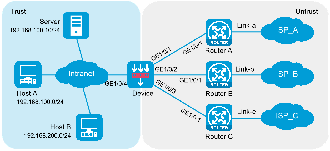
Configure ICMP probe templates.
# On the top navigation bar, click Objects.
# From the navigation pane, click Health Monitoring.
# Click Create.
# In the dialog box that opens, configure an ICMP probe template named ta, as shown in Figure 2.
Figure 2 Creating probe template ta
# Click OK.
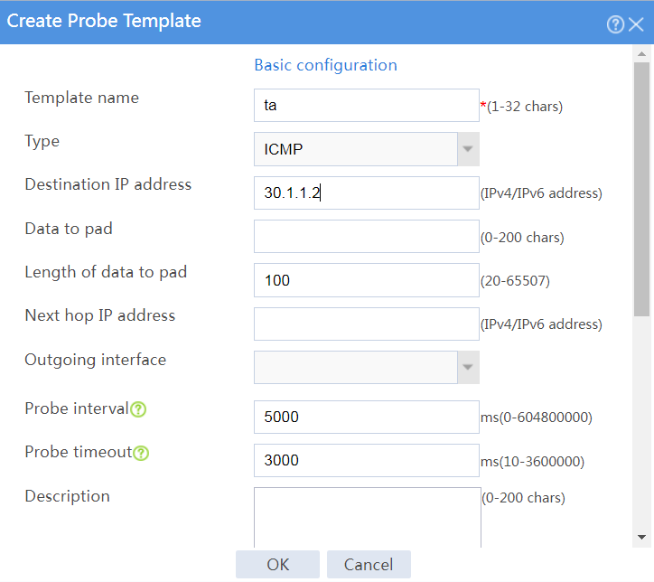
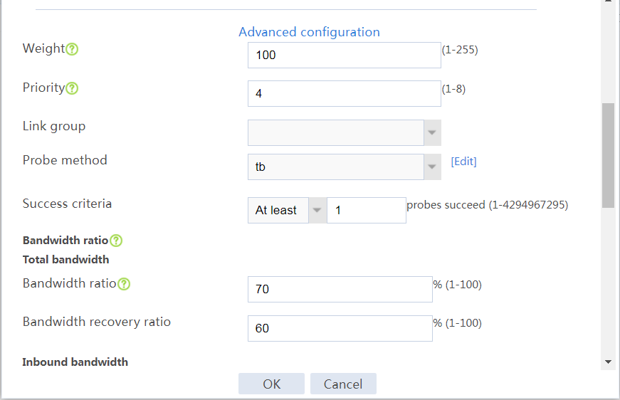
# Configure an ICMP probe template named tb, as shown in Figure 3.
Figure 3 Creating probe template tb
# Click OK.
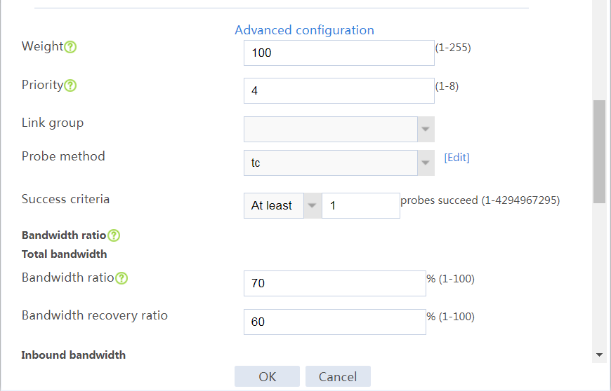
# Configure an ICMP probe template named tc, as shown in Figure 4.
Figure 4 Creating probe template tc
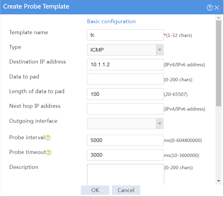
# Click OK.
Configure outbound dynamic NAT rules.
# On the top navigation bar, click Policies.
# From the navigation pane, select Interface NAT > IPv4 > Dynamic NAT.
# On the Outbound Dynamic NAT (Object Group-Based) tab, click Create.
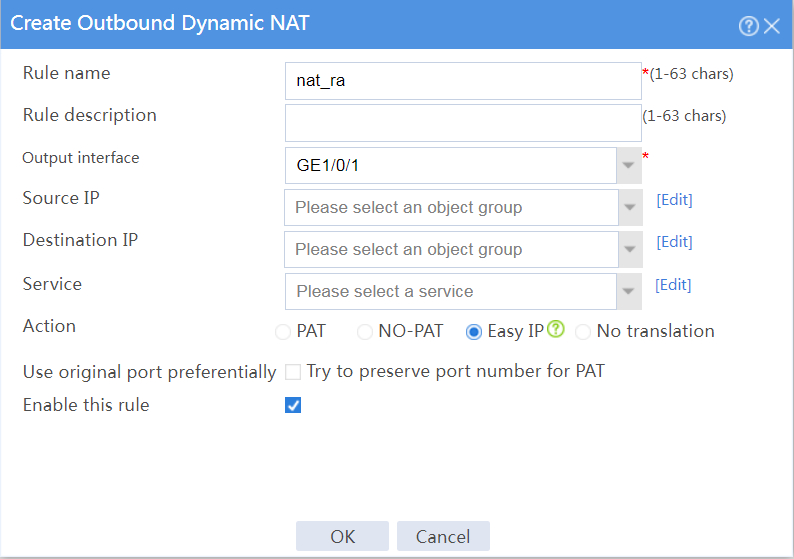
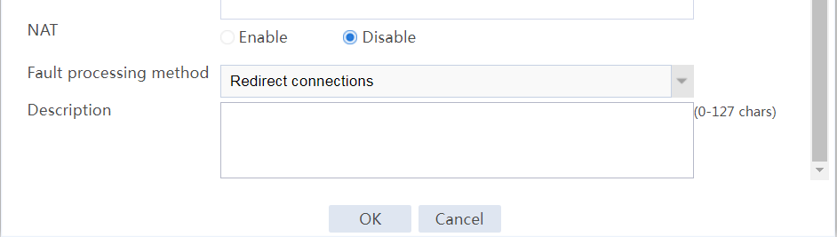
# Create an outbound dynamic NAT rule named nat_ra, as shown in Figure 5:
Enter rule name nat_ra.
Select output interface GE1/0/1.
Select action Easy IP.
Select Enable this rule.
Click OK.
Figure 5 Configuring an outbound dynamic NAT rule named nat_ra
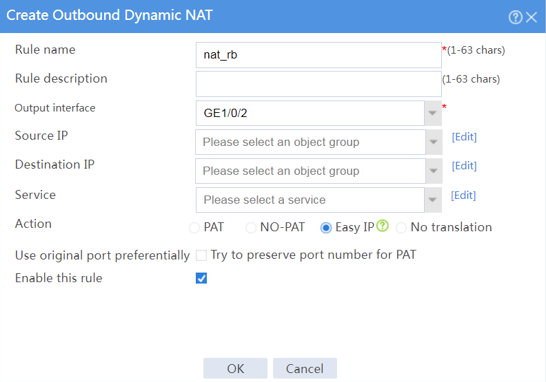
# Create an outbound dynamic NAT rule named nat_rb, as shown in Figure 6:
Enter rule name nat_rb.
Select output interface GE1/0/2.
Select action Easy IP.
Select Enable this rule.
Click OK.
Figure 6 Configuring an outbound dynamic NAT rule named nat_rb
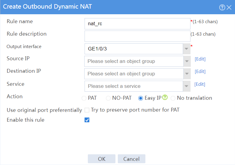
# Create an outbound dynamic NAT rule named nat_rc, as shown in Figure 7:
Enter rule name nat_rc.
Select output interface GE1/0/3.
Select action Easy IP.
Select Enable this rule.
Click OK.
Figure 7 Configuring an outbound dynamic NAT rule named nat_rc
Configure links.
# On the top navigation bar, click Polices.
# From the navigation pane, select Load Balancing > Links.
# Click Create.
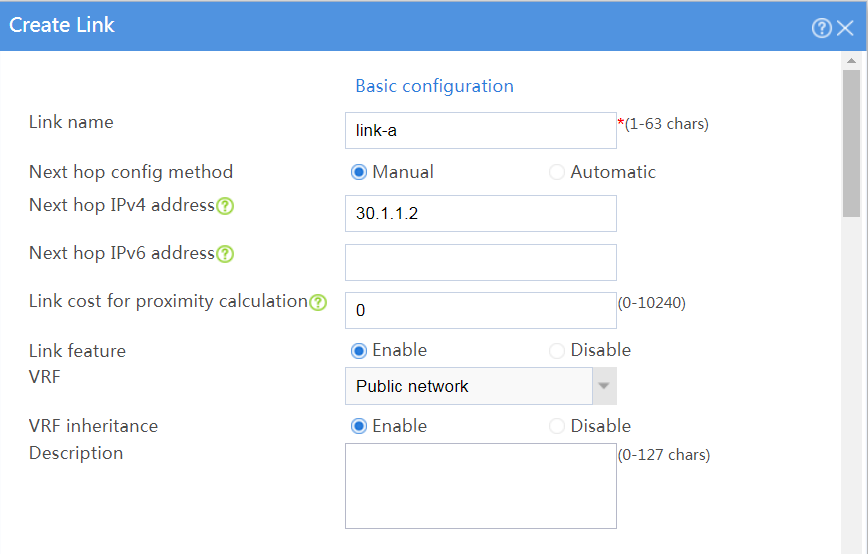
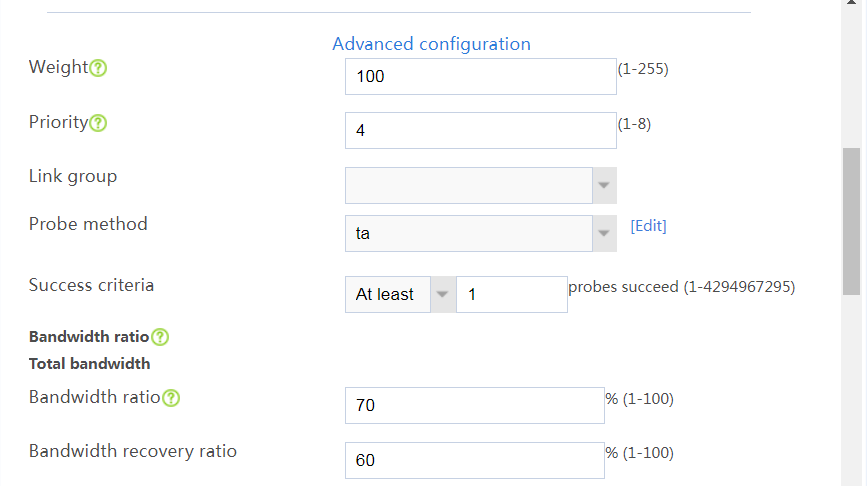
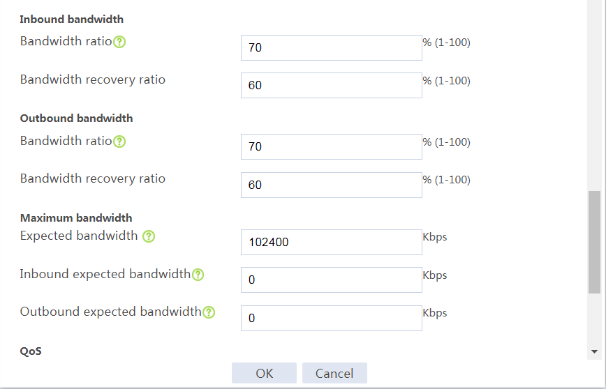
# In the dialog box that opens, configure a link named link-a as shown in Figure 8.
# Click OK.
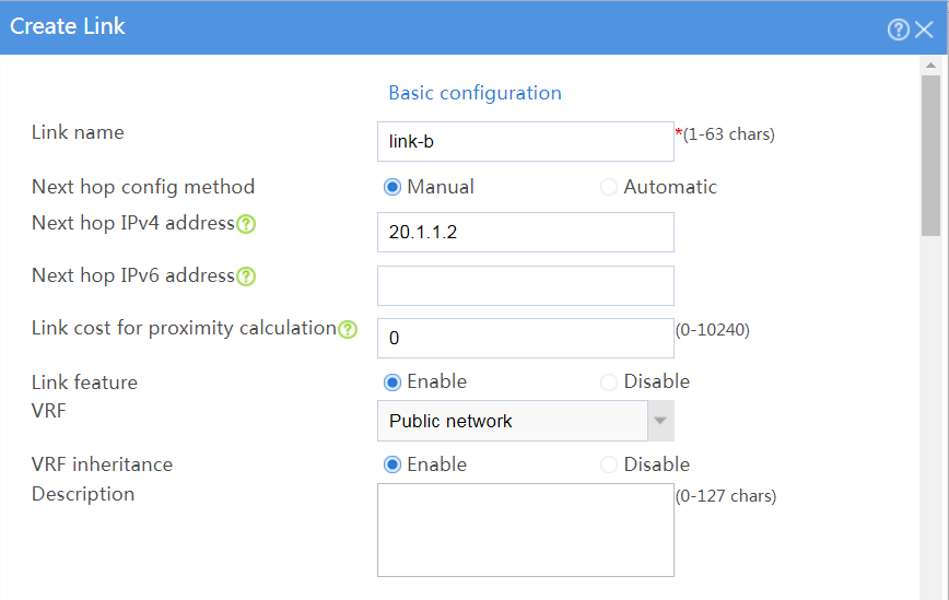
# Click Create.
# In the dialog box that opens, configure a link named link-b as shown in Figure 9.
# Click OK.

# Click Create.
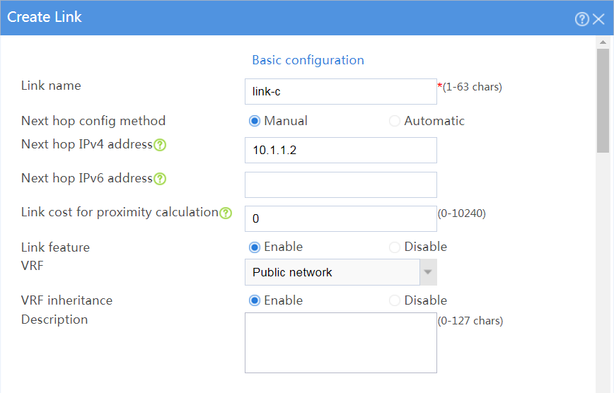
# In the dialog box that opens, configure a link named link-c as shown in Figure 10.
# Click OK.
Figure 10 Creating link link-c

Configure link groups.
# On the top navigation bar, click Polices.
# From the navigation pane, select Link Load Balancing > Outbound Link LB.
# On the Link Group tab, click Create.
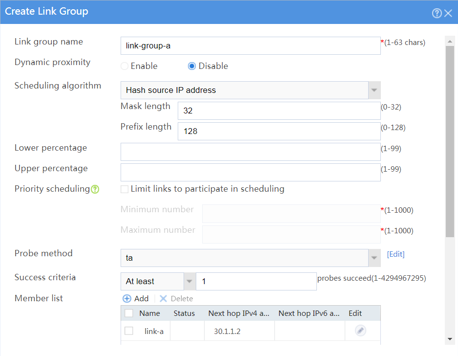
# In the dialog box that opens, configure a link group named link-group-a as shown in Figure 11.
# Click OK.
Figure 11 Creating link group link-group-a
# On the Link Group tab, click Create.
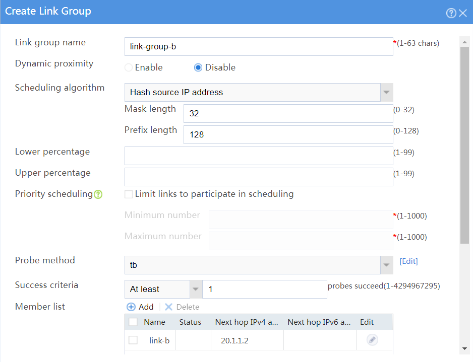
# In the dialog box that opens, configure a link group named link-group-b as shown in Figure 12.
# Click OK.
Figure 12 Creating link group link-group-b
# On the Link Group tab, click Create.
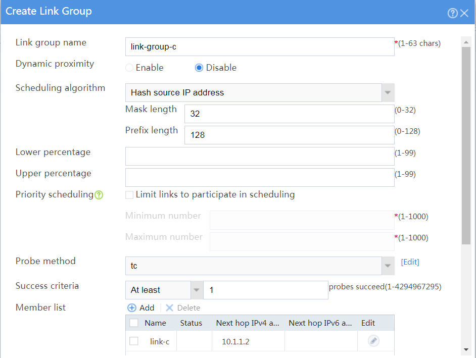
# In the dialog box that opens, configure a link group named link-group-c as shown in Figure 13
# Click OK.
Figure 13 Creating link group link-group-c
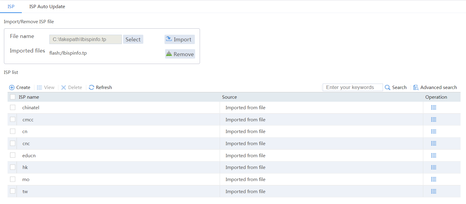
Import ISP information.
# On the top navigation bar, click Polices.
# From the navigation pane, select Load Balancing > ISP.
# Select file lbispinfo.tp.
# Click Import.
Figure 14 Importing ISP information
Configure classes.
# On the top navigation bar, click Polices.
# From the navigation pane, select Link Load Balancing > Outbound Link LB.
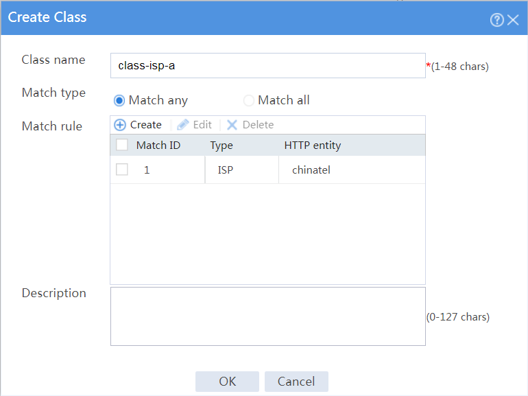
# On the Class tab, click Create.
# In the dialog box that opens, configure a class named class-isp-a as shown in Figure 15.
# Click OK.
Figure 15 Creating class class-isp-a
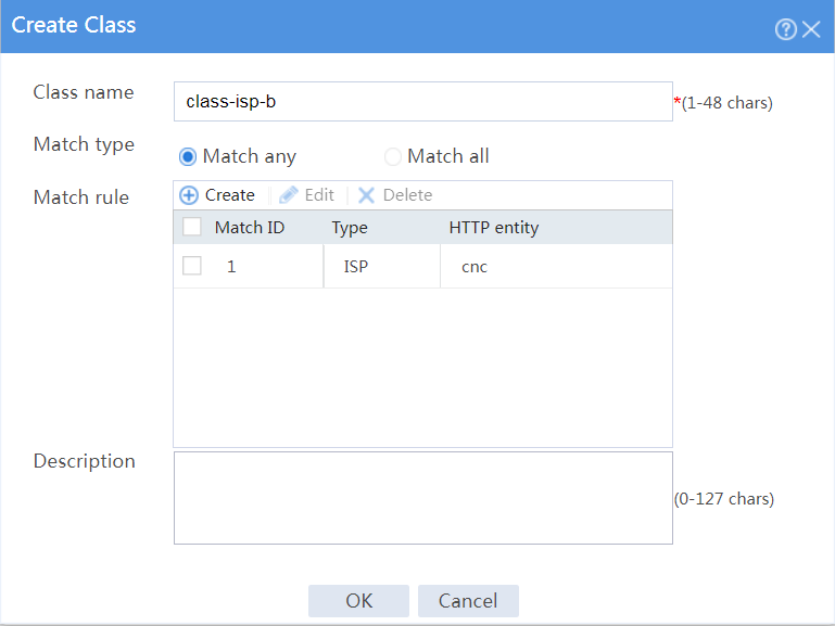
# On the Class tab, click Create.
# In the dialog box that opens, configure a class named class-isp-b as shown in Figure 16.
# Click OK.
Figure 16 Creating class class-isp-b
# On the Class tab, click Create.
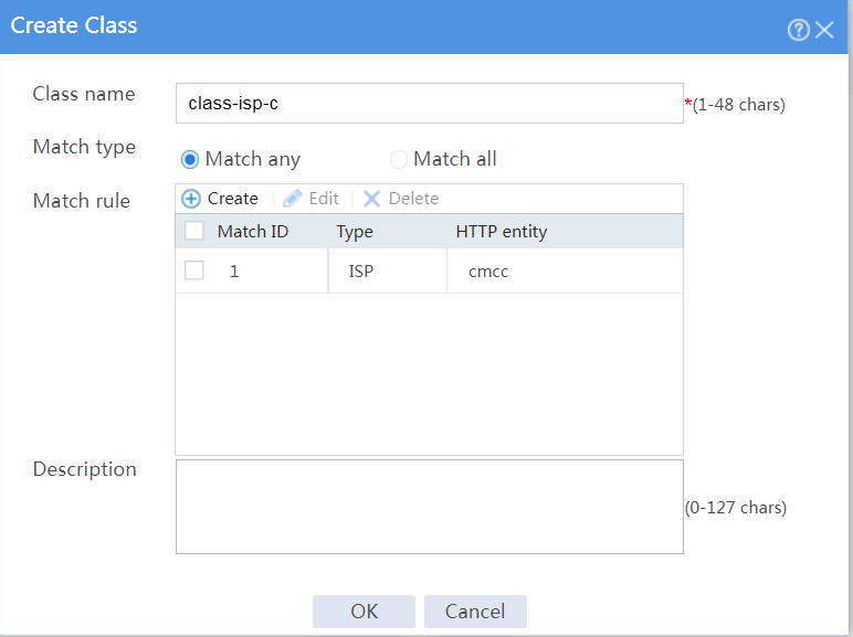
# In the dialog box that opens, configure a class named class-isp-c as shown in Figure 17.
# Click OK.
Figure 17 Creating class class-isp-c
# On the Class tab, click Create.
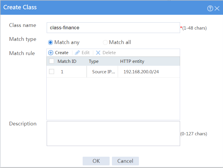
# In the dialog box that opens, configure a class named class-finance as shown in Figure 18.
# Click OK.
Figure 18 Creating class class-finance
Configure IPv4 routing policies.
# On the top navigation bar, click Polices.
# From the navigation pane, select Link Load Balancing > Outbound Link LB.
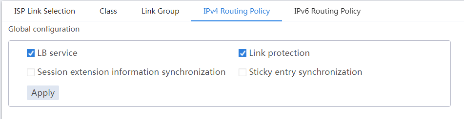
# In the Global configuration area on the IPv4 Routing Policy tab, select LB service and Link protection.
Figure 19 Global configuration
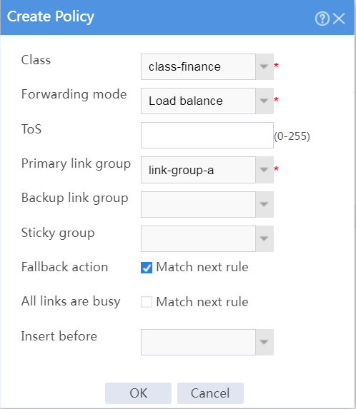
# In the Policy area on the IPv4 Routing Policy tab, click Create.
# In the dialog box that opens, configure an IPv4 routing policy for class class-finance:
Select class class-finance.
Select forwarding mode Load balance.
Select primary link group link-group-a.
Select Match next rule for the Fallback action field.
Click OK.
Figure 20 Creating a policy for class class-finance
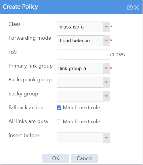
# In the Policy area on the IPv4 Routing Policy tab, click Create.
# In the dialog box that opens, configure an IPv4 routing policy for class class-isp-a:
Select class class-isp-a.
Select forwarding mode Load balance.
Select primary link group link-group-a.
Select Match next rule for the Fallback action field.
Click OK.
Figure 21 Creating a policy for class class-isp-a
# In the Policy area on the IPv4 Routing Policy tab, click Create.
# In the dialog box that opens, configure an IPv4 routing policy for class class-isp-b:
Select class class-isp-b.
Select forwarding mode Load balance.
Select primary link group link-group-b.
Select Match next rule for the Fallback action field.
Click OK.
Figure 22 Creating a policy for class class-isp-b

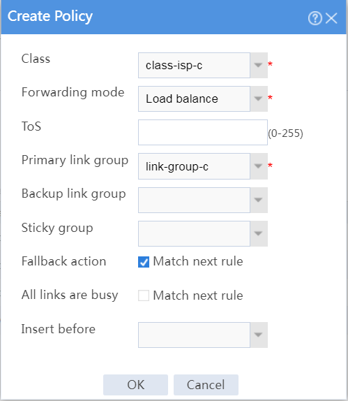
# In the Policy area on the IPv4 Routing Policy tab, click Create.
# In the dialog box that opens, configure an IPv4 routing policy for class class-isp-c:
Select class class-isp-c.
Select forwarding mode Load balance.
Select primary link group link-group-c.
Select Match next rule for the Fallback action field.
Click OK.
Figure 23 Creating a policy for class class-isp-c
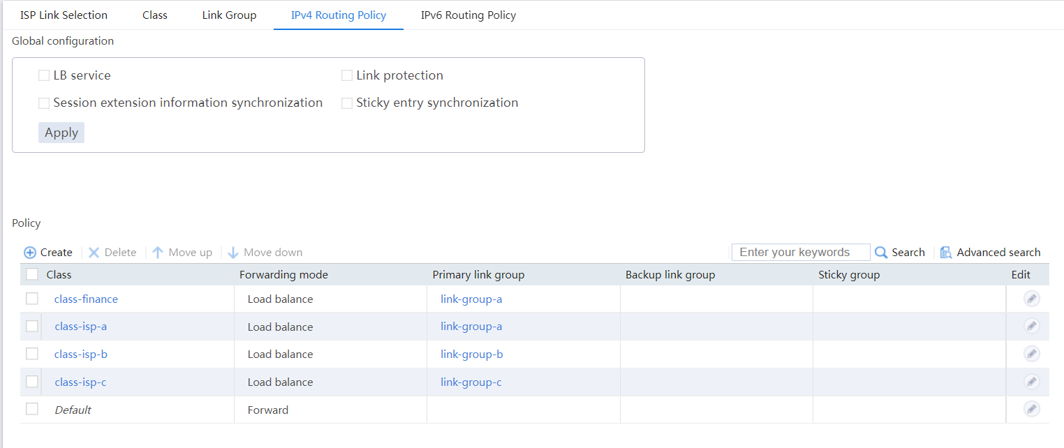
# View the configured IPv4 routing policies as shown in Figure 24.
Figure 24 IPv4 routing policies
# On the top navigation bar, click the Monitor tab.
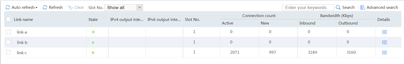
# From the navigation pane, select Statistics > Outbound Link LB Statistics > Links.
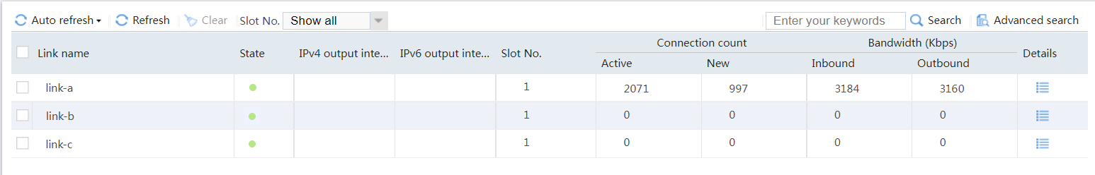
# View the statistics of link link-a as shown in Figure 25. Traffic from subnet 192.168.200.0/24 in the finance department matches class class-finance, and is distributed to link group link-group-a.
Figure 25 Statistics of traffic from the finance department
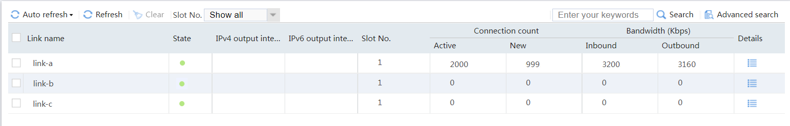
# View the statistics of link link-a as shown in Figure 26. Traffic destined for ISP-A matches class class-isp-a, and is distributed to link group link-group-a.
Figure 26 Statistics of traffic destined for ISP_A
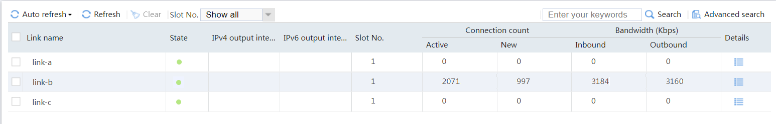
# View the statistics of link link-b as shown in Figure 27. Traffic destined for ISP-B belongs to class class-isp-b, and is distributed to link group link-group-b.
Figure 27 Statistics of traffic destined for ISP_B
# View the statistics of link link-c as shown in Figure 28. Traffic destined for ISP_C belongs to class class-isp-c, and is distributed to link group link-group-c.
Figure 28 Statistics of traffic destined for ISP_C