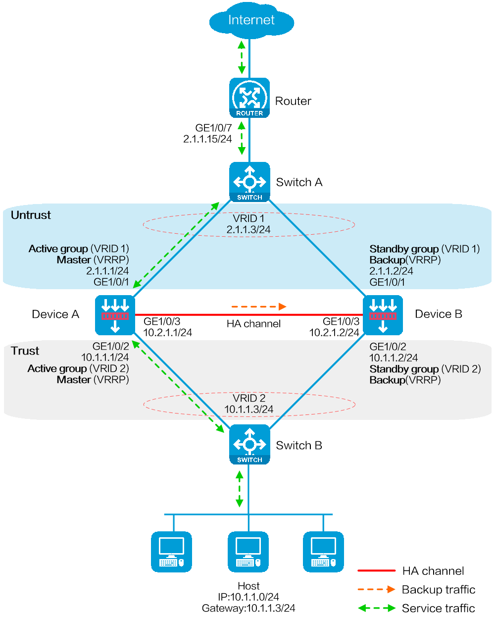
As shown in Figure 1, set up a hot backup system at the border between the Internet and the internal network of an enterprise to ensure service continuity.
Configure the hot backup system to collaborate with VRRP.
Configure the hot backup system to operate in active/standby mode.
Configure Device A and Device B as the primary device and the secondary device, respectively.
This configuration example was created and verified on E8371 of the F5000-AI160 device.
Verify that the devices to be assigned to a hot backup system meet the hardware and software environment consistency requirements in this section.
Before you configure a hot backup system, verify that the following hardware settings are the same on the devices to be assigned to the hot backup system:
Device model.
Number and type of management interfaces, service interfaces, interfaces for setting up the control channel, and interfaces for setting up the data channel. Do not use one interface for multiple purposes.
Location, number, and type of disks. A device without disks installed has small log storage and does not support some types of logs or reports.
Before you configure a hot backup system, verify that the following software settings are the same on the devices to be assigned to the hot backup system:
Software environment and version, including boot packages, system packages, feature packages, and patches.
Licensed signature libraries and features, such as signature library types, signature library version, validation time, and number of licensed resources.
Interface numbers.
Type, speed, and number of the interfaces for setting up the control channel. As a best practice, use aggregate interfaces.
Type, speed, and number of the interfaces for setting up the data channel. As a best practice, use aggregate interfaces.
Aggregate interface numbers and aggregation member port numbers.
Security zone configuration on the interfaces at the same location.
If you configure both VRRP and NAT on a hot backup system, you must associate NAT configuration with VRRP groups, such as NAT rules, source translation methods, and NAT server mappings. If you fail to do so, NAT cannot operate correctly.
For SSL VPN to operate correctly on a hot backup system, you must configure the port used for transmitting user data for the hot backup system on the global setting configuration page of SSL VPN.
You can use SSL VPN only when the hot backup system is operating in active/standby mode and collaborating with VRRP. You cannot use SSL VPN in any other scenario.
If asymmetric-path traffic exists on the transparent in-path hot backup operating in dual-active mode, enable DPI services to support the hot backup feature on the advanced setting configuration page of application security. If you fail to do so, application security services cannot identify or process traffic correctly.
# Create VLAN 10.
# Configure the interfaces attached to the hot backup system and the router to operate at Layer 2. Assign them to VLAN 10 as access interfaces.
# Create VLAN 10.
# Configure the interfaces attached to the hot backup system and the host to operate at Layer 2. Assign them to VLAN 10 as access interfaces.
# Assign 2.1.1.15/24 to GigabitEthernet 1/0/7.
# Configure routes as follows:
Specify 2.1.1.3 (virtual IP address of VRRP group 1) as the next hop of the routes to the internal network.
Specify the IP address of the peer interface attached to the traffic outgoing interface as the next hop of the route to the Internet.
Assign IP addresses to interfaces:
# On the top navigation bar, click Network.
# From the navigation pane, select Interface Configuration > Interfaces.
# Click the Edit icon for GE 1/0/1.
# In the dialog box that opens, configure the interface:
On the Basic Configuration tab, select the Untrust security zone.
On the IPv4 Address tab, enter the IP address and mask of the interface. In this example, enter 2.1.1.1/24.
Use the default settings for other parameters.
Click OK.
# Add GE 1/0/2 to the Trust security zone and assign 10.1.1.1/24 to it in the same way you configure GE 1/0/1.
# Assign 10.2.1.1/24 to GE 1/0/3 in the same way you configure GE 1/0/1.
Configure routing:
This step uses static routing as an example. To use dynamic routing, configure a dynamic routing protocol.
# On the top navigation bar, click Network.
# From the navigation pane, select Routing > Static Routing.
# On the IPv4 Static Routing tab, click Create.
# In the dialog box that opens, configure an IPv4 static route:
Enter destination IP address 0.0.0.0.
Enter mask length 0.
Enter next hop address 2.1.1.15.
Use the default settings for other parameters.
Click OK.
Configure a security policy to permit service traffic:
Perform this task only on the primary device. The secondary device will synchronize security policy configuration with the primary device after the hot backup system is set up.
# On the top navigation bar, click Policies.
# From the navigation pane, select Security Policies > Security Policies.
# Select Create > Create a policy.
# In the dialog box that opens, configure a security policy to permit traffic from zone Trust to zone Untrust:
Enter security policy name Trust-Untrust.
Select source zone Trust.
Select destination zone Untrust.
Select IP version IPv4.
Set the action to Permit.
Enter source IP address 10.1.1.0/24.
Use the default settings for other parameters.
Click OK.
Configure security policies to permit VRRP protocol packets:
This task allows Device A and Device B to exchange VRRP packets and elect a VRRP master when the RBM channels are disconnected.
Perform this task only on the primary device. The secondary device will synchronize security policy configuration with the primary device after the hot backup system is set up.
# On the top navigation bar, click Policies.
# From the navigation pane, select Security Policies > Security Policies.
# Select Create > Create a policy.
# In the dialog box that opens, configure a security policy to permit traffic from zone Trust to zone Local:
Enter security policy name vrrp1.
Select source zone Trust.
Select destination zone Local.
Select IP version IPv4.
Set the action to Permit.
Select policy group vrrp.
Use the default settings for other parameters.
Click OK.
# Configure a security policy to permit traffic from zone Local to zone Trust:
Enter security policy name vrrp2.
Select source zone Local.
Select destination zone Trust.
Select IP version IPv4.
Set the action to Permit.
Select policy group vrrp.
Use the default settings for other parameters.
Click OK.
# Configure a security policy to permit traffic from zone Untrust to zone Local:
Enter security policy name vrrp3.
Select source zone Untrust.
Select destination zone Local.
Select IP version IPv4.
Set the action to Permit.
Select policy group vrrp.
Use the default settings for other parameters.
Click OK.
# Configure a security policy to permit traffic from zone Local to zone Untrust:
Enter security policy name vrrp4.
Select source zone Local.
Select destination zone Untrust.
Select IP version IPv4.
Set the action to Permit.
Select policy group vrrp.
Use the default settings for other parameters.
Click OK.
# On the top navigation bar, click System.
# From the navigation pane, select High Availability > Hot Backup.
# Click Configure.
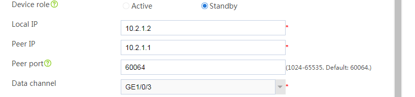
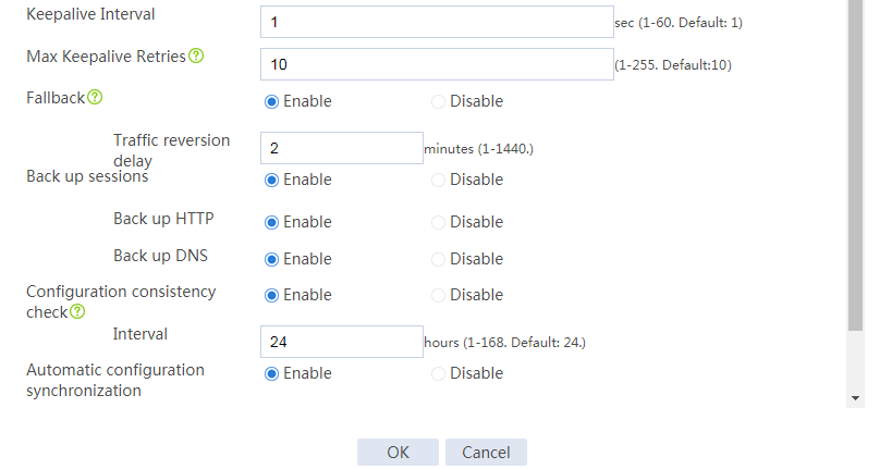
# Configure the hot backup parameters as shown in Figure 2.
Figure 2 Configuring hot backup parameters
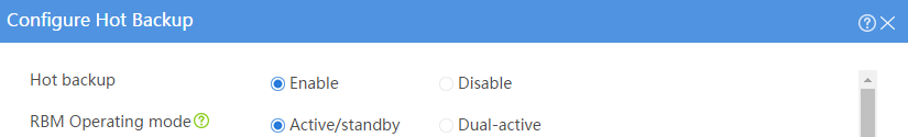
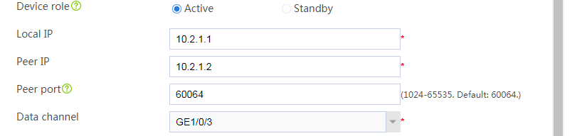

# Click OK.
# On the top navigation bar, click System.
# From the navigation pane, select High Availability > VRRP.
# Click Create.
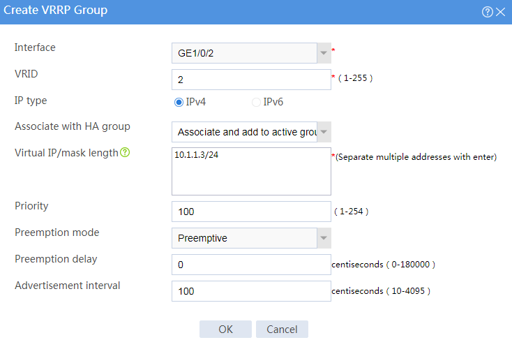
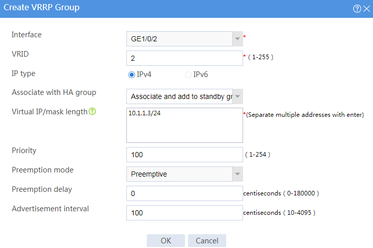
# Configure VRRP groups as shown in the follow figures.
Figure 3 Creating VRRP group 1
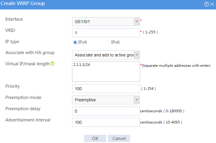
Figure 4 Creating VRRP group 2
# Click OK.
# Configure security devices on the hot backup member devices. If the hot backup system can back up configuration for a module, configure the module only on the primary device (Device A).
Assign IP addresses to interfaces:
# On the top navigation bar, click Network.
# From the navigation pane, select Interface Configuration > Interfaces.
# Click the Edit icon for GE 1/0/1.
# In the dialog box that opens, configure the interface:
On the Basic Configuration tab, select the Untrust security zone.
On the IPv4 Address tab, enter the IP address and mask of the interface. In this example, enter 2.1.1.2/24.
Use the default settings for other parameters.
Click OK.
# Add GE 1/0/2 to the Trust security zone and assign 10.1.1.2/24 to it in the same way you configure GE 1/0/1.
# Assign 10.2.1.2/24 to GE 1/0/3 in the same way you configure GE 1/0/1.
Configure routing:
This step uses static routing as an example. To use dynamic routing, configure a dynamic routing protocol.
# On the top navigation bar, click Network.
# From the navigation pane, select Routing > Static Routing.
# On the IPv4 Static Routing tab, click Create.
# In the dialog box that opens, configure an IPv4 static route:
Enter destination IP address 0.0.0.0.
Enter mask length 0.
Enter next hop address 2.1.1.15.
Use the default settings for other parameters.
Click OK.
# On the top navigation bar, click System.
# From the navigation pane, select High Availability > Hot Backup.
# Click Configure.
# Configure the hot backup parameters as shown in Figure 5.
Figure 5 Configuring hot backup parameters

# Click OK.
# On the top navigation bar, click System.
# From the navigation pane, select High Availability > VRRP.
# Click Create.
# Configure VRRP groups as shown in the follow figures.
Figure 6 Creating VRRP group 1
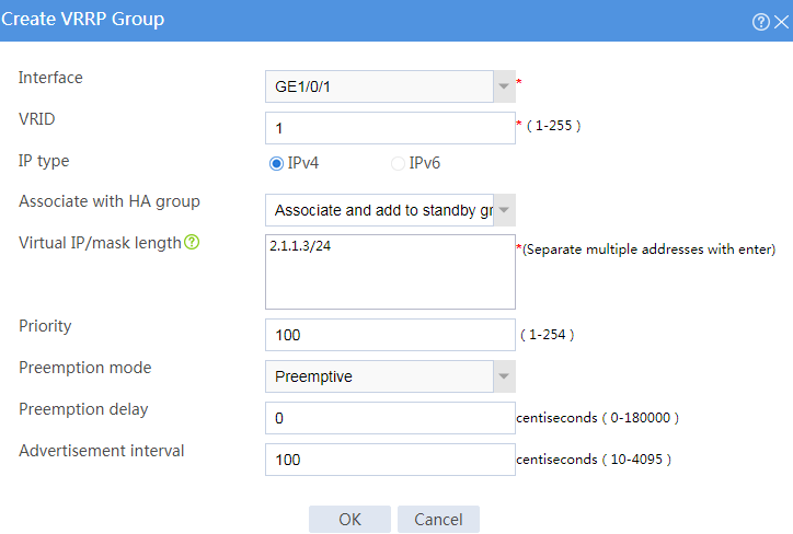
Figure 7 Creating VRRP group 2
# Click OK.
# On the host, specify 10.1.1.3 (virtual IP address of VRRP group 2) as the default gateway.
# Enable logging for the interzone policy that permits communication between security zones Trust and Untrust. Verity that only Device A generates log messages when the host communicates with the Internet.