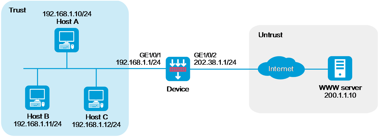
As shown in Figure 1, the company has public addresses 202.38.1.1/24 to 202.38.1.3/24. Configure policy-based source address translation to enable internal hosts to access the server on the Internet.
This configuration example was created and verified on E8371 of the F5000-AI160 device.
Do not configure both policy-based NAT and interface-based NAT.
Assign IP addresses to interfaces and add the interfaces to security zones.
# On the top navigation bar, click Network.
# From the navigation pane, select Interface Configuration > Interfaces.
# Click the Edit icon for GE 1/0/2.
# In the dialog box that opens, configure the interface:
Select the Untrust security zone.
On the IPv4 Address tab, enter the IP address and mask of the interface. In this example, enter 202.38.1.1/24.
Click OK.
# Add GE 1/0/1 to the Trust security zone and set its IP address to 192.168.1.1/24 in the same way you configure GE 1/0/2.
Configure settings for routing.
This example configures a static route. If dynamic routes are required, configure a dynamic routing protocol.
# On the top navigation bar, click Network.
# From the navigation pane, select Routing > Static Routing.
# On the IPv4 Static Routing tab, click Create.
# In the dialog box that opens, configure a static route to permit packets from the internal hosts to the external server:
Specify the IP address of the server as the destination IP. In this example, the address is 200.1.1.10.
Enter the mask length. In this example, enter 24.
Specify the next-hop address as 202.38.1.2.
Click OK.
Configure a security policy.
# On the top navigation bar, click Policies.
# From the navigation pane, select Security Policies > Security Policies.
# Click Create and click Create a policy.
# In the dialog box that opens, configure policy parameters as follows:
Enter a policy name. In this example, the name is Secpolicy.
Select the source zone. In this example, the source zone is Trust.
Select the destination zone. In this example, the destination zone is Untrust.
Select IPv4 as the type.
Select Permit as the action.
Specify the IP addresses of the hosts as the source IPv4 addresses. In this example, the addresses are 192.168.1.10, 192.168.1.11, and 192.168.1.12.
Specify the IP address of the server as the destination IPv4. In this example, the address is 200.1.1.10.
Click OK.
Configure a NAT address group.
# On the top navigation bar, click Objects.
# From the navigation pane, select Object Groups > NAT Address Groups.
# Click Create.
# Create a NAT address group, as shown in Figure 2.
Figure 2 Creating a NAT address group
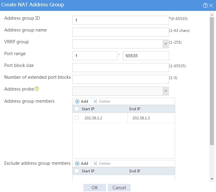
# Click OK.
Configure a policy-based NAT rule.
# On the top navigation bar, click Policies.
# From the navigation pane, select NAT > Policy-based NAT.
# Click Create.
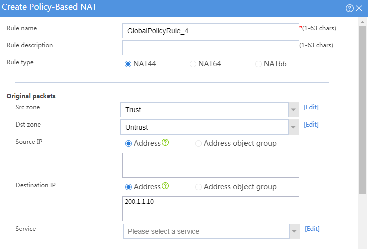
# Create a policy-based NAT rule, as shown in Figure 3.
Figure 3 Creating a policy-based NAT rule
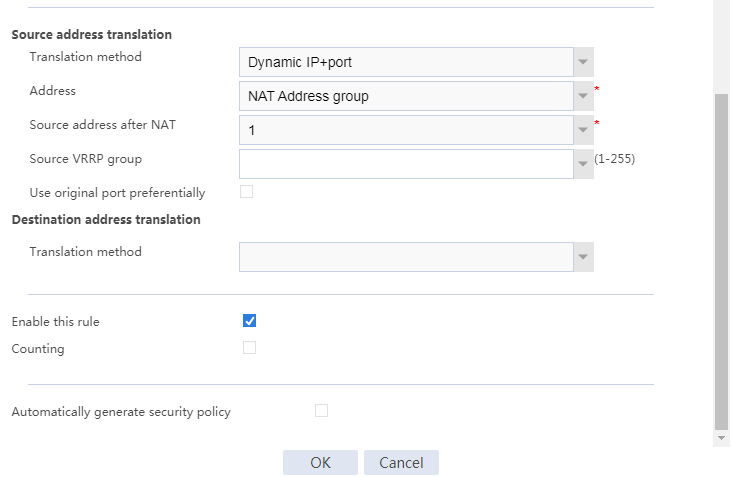
# Click OK.
Verify that the host can successfully ping the server on the external network.
C:\Users\abc>ping 200.1.1.10
Pinging host.com [200.1.1.10] with 32 bytes of data:
Reply from 200.1.1.10: bytes=32 time<1ms TTL=253
Reply from 200.1.1.10: bytes=32 time<1ms TTL=253
Reply from 200.1.1.10: bytes=32 time<1ms TTL=253
Reply from 200.1.1.10: bytes=32 time<1ms TTL=253
Ping statistics for 200.1.1.10:
Packets: Sent = 4, Received = 4, Lost = 0 (0% loss),
Approximate round trip times in milli-seconds: