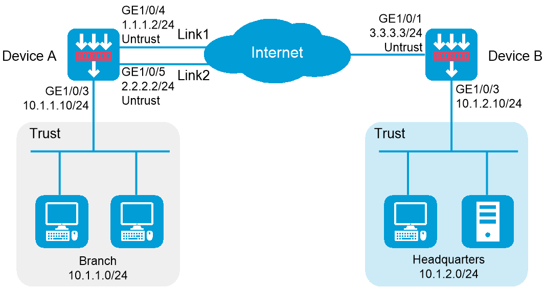
As shown in Figure 1, Device A is the IPsec gateway of the branch. Device B is the IPsec gateway of the headquarters. Configure IPsec smart link selection so the branch can establish an IPsec tunnel to the headquarters over link 1 or link 2, whichever has a better link quality.
Device A first uses link 1 to establish the IPsec tunnel.
When link 1 suffers high packet loss ratio or delay, Device A automatically switches traffic to the IPsec tunnel established based on link 2.
This configuration example was created and verified on E8371 of the F5000-AI160 device.
When you specify the remote host name in an IPsec policy, follow these restrictions and guidelines:
If the remote host name is resolved by a DNS server, the local device gets the latest IP address corresponding to the host name by sending a query to the DNS server when the cached DNS entry ages. The DNS entry aging information is obtained from the DNS server.
If the remote host name is resolved by a locally configured static DNS entry and the IP address in the entry is changed, you must respecify the remote host name in the IPsec policy to get the new IP address.
To make sure SAs can be set up and the traffic protected by IPsec can be processed correctly between two IPsec peers, create mirror image ACLs on the IPsec peers. If the ACL rules on IPsec peers do not form mirror images of each other, SAs can be set up only when both of the following requirements are met:
The range specified by an ACL rule on one peer is covered by its counterpart ACL rule on the other peer.
The peer with the narrower rule initiates SA negotiation.
If a wider ACL rule is used by the SA initiator, the negotiation request might be rejected because the matching traffic is beyond the scope of the responder.
If you do not configure the local identity in an IPsec policy, the policy uses the global local identity settings configured in the advanced settings.
Modifications to the following settings in an IPsec policy take effect only on IPsec SAs set up after the modifications:
Encapsulation mode.
Security protocol.
Security algorithms.
PFS.
IPsec SA lifetimes.
IPsec SA idle timeout.
For the modifications to take effect on existing IPsec SAs, you must reset the IPsec SAs.
The IPsec peers of an IPsec tunnel must have IPsec policies that use the same security protocols, security algorithms, and encapsulation mode.
When IKE negotiates IPsec SAs, it uses the IPsec SA lifetime settings configured in the IPsec policy to negotiate the IPsec SA lifetime with the peer. If the IPsec SA lifetime settings are not configured in the IPsec policy, the global IPsec SA lifetime settings are used. IKE uses the local lifetime settings or those proposed by the peer, whichever are smaller.
Assign IP addresses to interfaces and add the interfaces to security zones:
# On the top navigation bar, click Network.
# From the navigation pane, select Interface Configuration > Interfaces.
# Click the Edit icon for GE 1/0/4.
# In the dialog box that opens, configure the interface:
Select the Untrust security zone.
Click the IPv4 Address tab. Enter the IP address and mask length of the interface. In this example, use 1.1.1.2/24. Specify the gateway address for the interface as 1.1.1.3.
Use the default settings for other parameters.
Click OK.
# Add GE 1/0/5 to the Trust security zone and set its IP address to 2.2.2.2/24 and its gateway address to 2.2.2.3 in the same way you configure GE 1/0/4.
# Add GE 1/0/3 to the Trust security zone and set its IP address to 10.1.1.10/24 in the same way you configure GE 1/0/4.
Configure security policies:
# On the top navigation bar, click Policies.
# From the navigation pane, select Security Policies > Security Policies.
# Click Create, and then click Create a policy.
# Configure a security policy named trust-untrust to permit specific traffic from the Trust to Untrust security zones:
Set the security policy name to trust-untrust.
Select source zone Trust.
Select destination zone Untrust.
Select IPv4 as the type.
Select action Permit.
Enter source IPv4 address 10.1.1.0/24.
Enter destination IPv4 address 10.1.2.0/24.
Use the default settings for other parameters.
Click OK.
# On the Security Policies page, click Create.
# Configure a security policy named untrust-trust to permit specific traffic from the Untrust to Trust security zones:
Set the security policy name to untrust-trust.
Select source zone Untrust.
Select destination zone Trust.
Select IPv4 as the type.
Select action Permit.
Enter source IPv4 address 10.1.2.0/24.
Enter destination IPv4 address 10.1.1.0/24.
Use the default settings for other parameters.
Click OK.
# On the Security Policies page, click Create.
# Configure a security policy named local-untrust to permit specific traffic from the Local to Untrust security zones:
Set the security policy name to local-untrust.
Select source zone Local.
Select destination zone Untrust.
Select IPv4 as the type.
Select action Permit.
Enter source IPv4 address 1.1.1.2,2.2.2.2.
Enter destination IPv4 address 3.3.3.3.
Use the default settings for other parameters.
Click OK.
# On the Security Policies page, click Create.
# Configure a security policy named untrust-local to permit specific traffic from the Untrust to Local security zones:
Set the security policy name to untrust-local.
Select source zone Untrust.
Select destination zone Local.
Select IPv4 as the type.
Select action Permit.
Enter source IPv4 address 3.3.3.3.
Enter destination IPv4 address 1.1.1.2,2.2.2.2.
Use the default settings for other parameters.
Click OK.
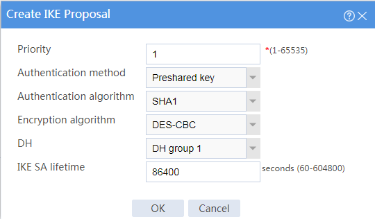
Create an IKE proposal:
# On the top navigation bar, click Network.
# From the navigation pane, select VPN > IPsec > IKE Proposals.
# Click Create.
Set the priority to 1.
Select the preshared key authentication method.
Select the SHA1 authentication algorithm.
Select the DES-CBC encryption algorithm.
Use the default settings for other parameters.
# Click OK.
Figure 2 Creating an IKE proposal

Configure the IPsec policy:
# On the top navigation bar, click Network.
# From the navigation pane, select VPN > IPsec > IPsec Policies.
# Click Create.
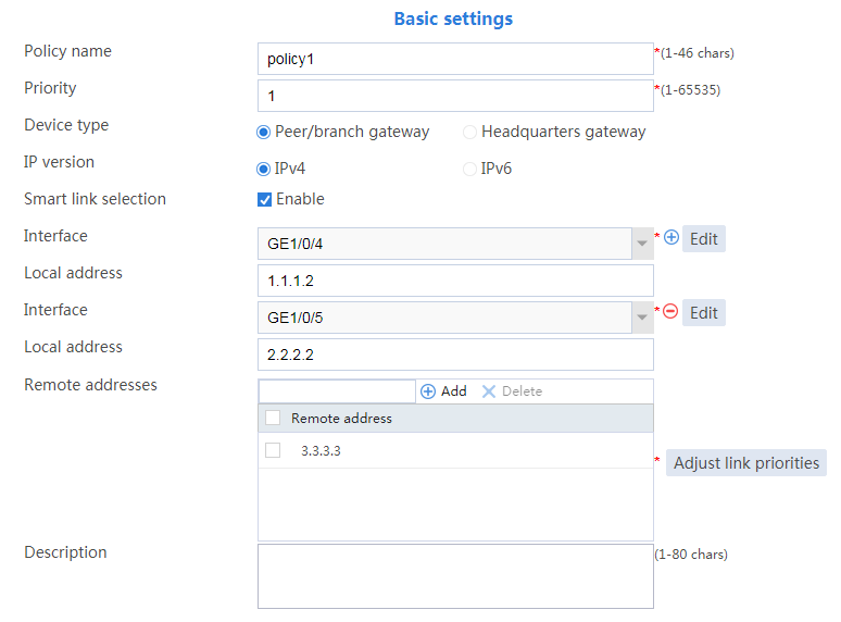
# Configure the basic settings as follows:
Set the policy name to policy1.
Set the priority to 1.
Set the device type to Peer/branch gateway.
Set the IP version to IPv4.
Enable smart link selection.
Select interface GE1/0/4 and GE1/0/5.
Figure 3 Basic settings
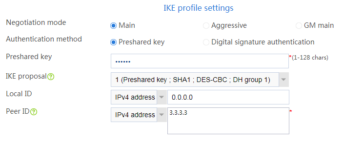
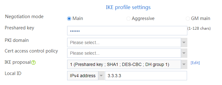
# Configure the IKE profile settings as follows:
Set the negotiation mode as Main.
Set the authentication method as Preshared key.
Enter the preshared key string.
Select IKE proposal 1 (Preshared key; SHA1; DES-CBC; DH group 1).
Set the local ID as IPv4 address 0.0.0.0.
Set the peer ID as IPv4 address 3.3.3.3.
Figure 4 IKE profile settings
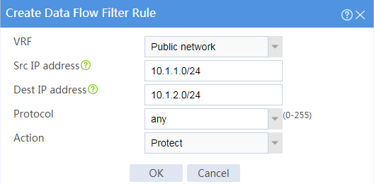
# Configure the data flow filter rules as follows:
Click Create.
Set the source IP address as 10.1.1.0/24.
Set the destination IP address as 10.1.2.0/24.
# Click OK.
Figure 5 Creating a data flow filter rule
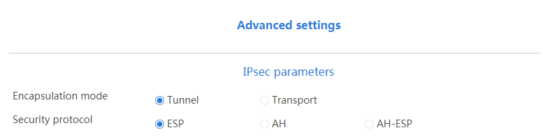
# Configure the IPsec advanced settings as follows:
Select the Tunnel encapsulation mode.
Select the ESP security protocol.
# Click OK.
Figure 6 Advanced settings
Assign IP addresses to interfaces and add the interfaces to security zones:
# On the top navigation bar, click Network.
# From the navigation pane, select Interface Configuration > Interfaces.
# Click the Edit icon for GE 1/0/1.
# In the dialog box that opens, configure the interface:
Select the Untrust security zone.
Click the IPv4 Address tab. Enter the IP address and mask length of the interface. In this example, use 3.3.3.3/24. Specify the gateway address for the interface as 3.3.3.4.
Use the default settings for other parameters.
Click OK.
# Add GE 1/0/3 to the Trust security zone and set its IP address to 10.1.2.10/24 in the same way you configure GE 1/0/1.
Configure security policies:
# On the top navigation bar, click Policies.
# From the navigation pane, select Security Policies > Security Policies.
# Click Create, and then click Create a policy.
# Configure a security policy named trust-untrust to permit specific traffic from the Trust to Untrust security zones:
Set the security policy name to trust-untrust.
Select source zone Trust.
Select destination zone Untrust.
Select IPv4 as the type.
Select action Permit.
Enter source IPv4 address 10.1.2.0/24.
Enter destination IPv4 address 10.1.1.0/24.
Use the default settings for other parameters.
Click OK.
# On the Security Policies page, click Create.
# Configure a security policy named untrust-trust to permit specific traffic from the Untrust to Trust security zones:
Set the security policy name to untrust-trust.
Select source zone Untrust.
Select destination zone Trust.
Select IPv4 as the type.
Select action Permit.
Enter source IPv4 address 10.1.1.0/24.
Enter destination IPv4 address 10.1.2.0/24.
Use the default settings for other parameters.
Click OK.
# On the Security Policies page, click Create.
# Configure a security policy named local-untrust to permit specific traffic from the Local to Untrust security zones:
Set the security policy name to local-untrust.
Select source zone Local.
Select destination zone Untrust.
Select IPv4 as the type.
Select action Permit.
Enter source IPv4 address 3.3.3.3.
Enter destination IPv4 addresses 1.1.1.2,2.2.2.2.
Use the default settings for other parameters.
Click OK.
# On the Security Policies page, click Create.
# Configure a security policy named untrust-local to permit specific traffic from the Untrust to Local security zones:
Set the security policy name to untrust-local.
Select source zone Untrust.
Select destination zone Local.
Select IPv4 as the type.
Select action Permit.
Enter source IPv4 addresses 1.1.1.2,2.2.2.2.
Enter destination IPv4 address 3.3.3.3.
Use the default settings for other parameters.
Click OK.
Create an IKE proposal:
# On the top navigation bar, click Network.
# From the navigation pane, select VPN > IPsec > IKE Proposals.
# Click Create.
Set the priority to 1.
Select the preshared key authentication method.
Select the SHA1 authentication algorithm.
Select the DES-CBC encryption algorithm.
Use the default settings for other parameters.
# Click OK.
Figure 7 Creating an IKE proposal
Configure the IPsec policy:
# On the top navigation bar, click Network.
# From the navigation pane, select VPN > IPsec > IPsec Policies.
# Click Create.
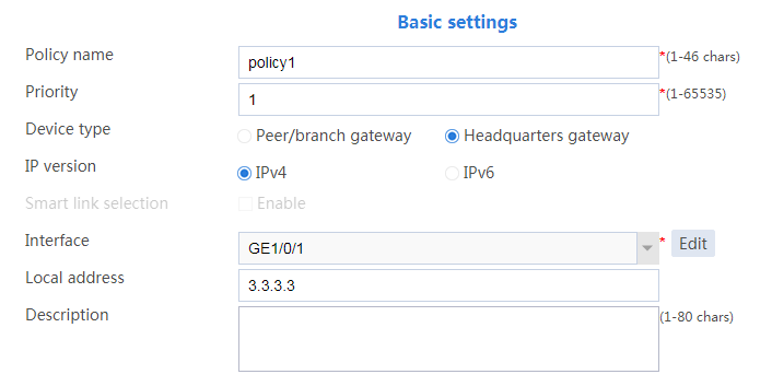
# Configure the basic settings as follows:
Set the policy name to policy1.
Set the priority to 1.
Set the device type to Headquarters gateway.
Set the IP version to IPv4.
Select interface GE1/0/1.
Figure 8 Basic settings
# Configure the IKE profile settings as follows:
Set the negotiation mode as Main.
Set the authentication method as Preshared key.
Enter the preshared key string.
Select IKE proposal 1 (Preshared key; SHA1; DES-CBC; DH group 1).
Set the local ID as IPv4 address 3.3.3.3.
Figure 9 IKE profile settings
# Configure the IPsec advanced settings as follows:
Select the Tunnel encapsulation mode.
Select the ESP security protocol.
# Click OK.
Figure 10 Advanced settings

Verify that Device A and Device B can communicate with each other.
On Device A, display IPsec tunnel information:
# On the top navigation bar, click Network.
# From the navigation pane, select VPN > IPsec > IPsec Tunnels. The established IPsec tunnel is displayed.
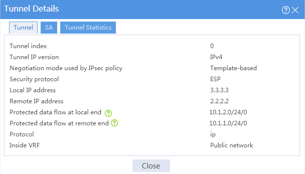
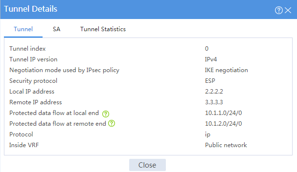
# Click the Details icon for the IPsec tunnel. The Tunnel Details page displays tunnel information, SA information, and tunnel statistics.
Figure 11 Details of the IPsec tunnel on Device A
On Device A, automatically or manually switch links:
# On the top navigation bar, click Network.
# From the navigation pane, select VPN > IPsec > IPsec Policies. In this example, the created IPsec policy policy1_1 is displayed, and IPsec smart link selection is enabled in the policy.
IPsec smart link selection enables the branch gateway to monitor the real-time packet loss ratio and delay of the active link over which the IPsec tunnel is established. The branch gateway can dynamically select a link with desired transmission quality to establish the IPsec tunnel to the headquarters.
Figure 12 IPsec policies
![]()
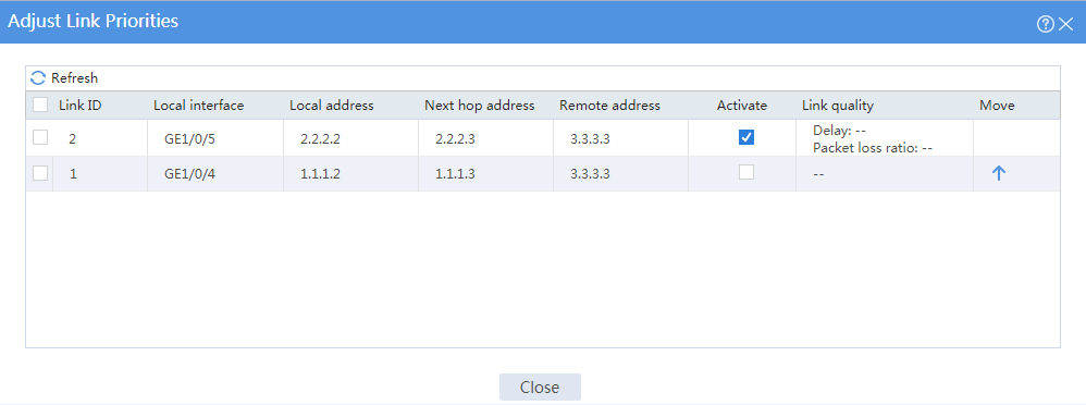
# Click Adjust in the Smart link selection column to open the Adjust Link Priorities page.
# Select the check box in the Activate column of a link to manually activate the link.
Figure 13 Adjust link priorities
On Device B, display IPsec tunnel information:
# On the top navigation bar, click Network.
# From the navigation pane, select VPN > IPsec > IPsec Tunnels. The established IPsec tunnel is displayed.
# Click the Details icon for the IPsec tunnel. The Tunnel Details page displays tunnel information, SA information, and tunnel statistics.
Figure 14 Details of the IPsec tunnel on Device B