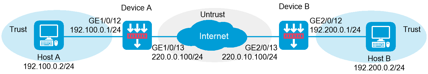
As shown in Figure 1, establish an IPsec tunnel between Device A and Device B to protect data flows between the subnets of Host A and Host B. Configure the tunnel as follows:
Set up SAs through IKE negotiation.
Configure IKE to use the 3DES-CBC encryption algorithm, the SHA256 authentication algorithm, and the preshared key authentication method.
Specify the IPsec encapsulation mode as tunnel and the security protocol as ESP
This configuration example was created and verified on E8371 of the F5000-AI160 device.
When you specify the remote host name in an IPsec policy, follow these restrictions and guidelines:
If the remote host name is resolved by a DNS server, the local device gets the latest IP address corresponding to the host name by sending a query to the DNS server when the cached DNS entry ages. The DNS entry aging information is obtained from the DNS server.
If the remote host name is resolved by a locally configured static DNS entry and the IP address in the entry is changed, you must respecify the remote host name in the IPsec policy to get the new IP address.
To make sure SAs can be set up and the traffic protected by IPsec can be processed correctly between two IPsec peers, create mirror image ACLs on the IPsec peers. If the ACL rules on IPsec peers do not form mirror images of each other, SAs can be set up only when both of the following requirements are met:
The range specified by an ACL rule on one peer is covered by its counterpart ACL rule on the other peer.
The peer with the narrower rule initiates SA negotiation.
If a wider ACL rule is used by the SA initiator, the negotiation request might be rejected because the matching traffic is beyond the scope of the responder.
If you do not configure the local identity in an IPsec policy, the policy uses the global local identity settings configured in the advanced settings.
Modifications to the following settings in an IPsec policy take effect only on IPsec SAs set up after the modifications:
Encapsulation mode.
Security protocol.
Security algorithms.
PFS.
IPsec SA lifetimes.
IPsec SA idle timeout.
For the modifications to take effect on existing IPsec SAs, you must reset the IPsec SAs.
The IPsec peers of an IPsec tunnel must have IPsec policies that use the same security protocols, security algorithms, and encapsulation mode.
When IKE negotiates IPsec SAs, it uses the IPsec SA lifetime settings configured in the IPsec policy to negotiate the IPsec SA lifetime with the peer. If the IPsec SA lifetime settings are not configured in the IPsec policy, the global IPsec SA lifetime settings are used. IKE uses the local lifetime settings or those proposed by the peer, whichever are smaller.
Assign IP addresses to interfaces and add the interfaces to security zones:
# On the top navigation bar, click Network.
# From the navigation pane, select Interface Configuration > Interfaces.
# Click the Edit icon for GE 1/0/13.
# In the dialog box that opens, configure the interface:
Select the Untrust security zone.
Click the IPv4 Address tab. Enter the IP address and mask length of the interface. In this example, use 220.0.0.100/24.
Use the default settings for other parameters.
Click OK.
# Add GE 1/0/12 to the Trust security zone and set its IP address to 192.100.0.1/24 in the same way you configure GE 1/0/13.
Configure settings for routing:
This example configures static routes.
# On the top navigation bar, click Network.
# From the navigation pane, select Routing > Static Routing.
# On the IPv4 Static Routing tab, click Create.
# In the dialog box that opens, configure a static route to reach 220.0.10.100:
Set the destination IP address to 220.0.10.100.
Set the mask length to 24.
Set the next hop address to 220.0.0.2.
Use the default settings for other parameters.
Click OK.
# On the IPv4 Static Routing tab, click Create.
# In the dialog box that opens, configure a static route to reach 192.200.0.2:
Set the destination IP address to 192.200.0.2.
Set the mask length to 24.
Set the next hop address to 220.0.0.2.
Use the default settings for other parameters.
Click OK.
Configure security policies:
# On the top navigation bar, click Policies.
# From the navigation pane, select Security Policies > Security Policies.
# Click Create, and then click Create a policy.
# Configure a security policy named trust-untrust to permit specific traffic from the Trust to Untrust security zones:
Set the security policy name to trust-untrust.
Select source zone Trust.
Select destination zone Untrust.
Select IPv4 as the type.
Select action Permit.
Enter source IPv4 address 192.100.0.0/24.
Enter destination IPv4 address 192.200.0.0/24.
Use the default settings for other parameters.
Click OK.
# On the Security Policies page, click Create.
# Configure a security policy named untrust-trust to permit specific traffic from the Untrust to Trust security zones:
Set the security policy name to untrust-trust.
Select source zone Untrust.
Select destination zone Trust.
Select IPv4 as the type.
Select action Permit.
Enter source IPv4 address 192.200.0.0/24.
Enter destination IPv4 address 192.100.0.0/24.
Use the default settings for other parameters.
Click OK.
# On the Security Policies page, click Create.
# Configure a security policy named local-untrust to permit specific traffic from the Local to Untrust security zones:
Set the security policy name to local-untrust.
Select source zone Local.
Select destination zone Untrust.
Select IPv4 as the type.
Select action Permit.
Enter source IPv4 address 220.0.0.100.
Enter destination IPv4 address 220.0.10.100.
Use the default settings for other parameters.
Click OK.
# On the Security Policies page, click Create.
# Configure a security policy named untrust-local to permit specific traffic from the Untrust to Local security zones:
Set the security policy name to untrust-local.
Select source zone Untrust.
Select destination zone Local.
Select IPv4 as the type.
Select action Permit.
Enter source IPv4 address 220.0.10.100.
Enter destination IPv4 address 220.0.0.100.
Use the default settings for other parameters.
Click OK.
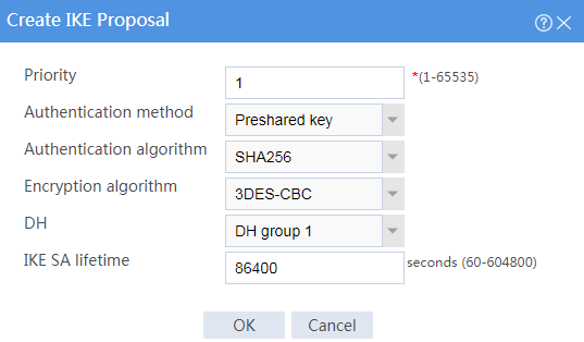
Create an IKE proposal:
# On the top navigation bar, click Network.
# From the navigation pane, select VPN > IPsec > IKE Proposals.
# Click Create.
Set the priority to 1.
Select the preshared key authentication method.
Select the SHA256 authentication algorithm.
Select the 3DES-CBC encryption algorithm.
Use the default settings for other parameters.
# Click OK.
Figure 2 Creating an IKE proposal

Configure the IPsec policy:
# On the top navigation bar, click Network.
# From the navigation pane, select VPN > IPsec > IPsec Policies.
# Click Create.
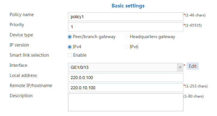
# Configure the basic settings as follows:
Set the policy name to policy1.
Set the priority to 1.
Set the device type to Peer/branch gateway.
Set the IP version to IPv4.
Select interface GE1/0/13.
Configure the local address as 220.0.0.100.
Configure the remote address/host name as 220.0.10.100.
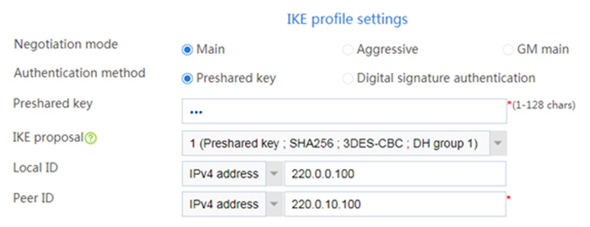
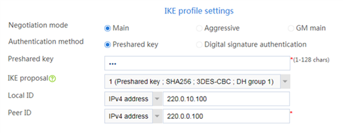
# Configure the IKE profile settings as follows:
Set the negotiation mode as Main.
Set the authentication method as Preshared key.
Enter the preshared key string.
Select IKE proposal 1 (Preshared key; SHA256; 3DES-CBC; DH group 1).
Set the local ID as IPv4 address 220.0.0.100.
Set the peer ID as IPv4 address 220.0.10.100.
Figure 4 IKE profile settings
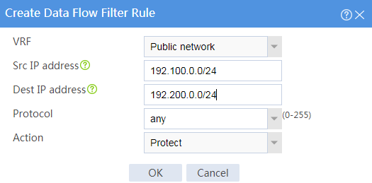
# Configure the data flow filter rules as follows:
Click Create.
Set the source IP address as 192.100.0.0/24.
Set the destination IP address as 192.200.0.0/24.
# Click OK.
Figure 5 Creating a data flow filter rule
# Set the IPsec SA triggering mode to Traffic-based.
# Configure the IPsec advanced settings as follows:
Select the Tunnel encapsulation mode.
Select the ESP security protocol.
# Click OK.
Assign IP addresses to interfaces and add the interfaces to security zones:
# On the top navigation bar, click Network.
# From the navigation pane, select Interface Configuration > Interfaces.
# Click the Edit icon for GE 2/0/13.
# In the dialog box that opens, configure the interface:
Select the Untrust security zone.
Click the IPv4 Address tab, and then enter the IP address and mask length of the interface. In this example, use 220.0.10.100/24.
Use the default settings for other parameters.
Click OK.
# Add GE 2/0/12 to the Trust security zone and set its IP address to 192.200.0.2/24 in the same way you configure GE 2/0/13.
Configure settings for routing:
This example configures static routes.
# On the top navigation bar, click Network.
# From the navigation pane, select Routing > Static Routing.
# On the IPv4 Static Routing tab, click Create.
# In the dialog box that opens, configure a static route to reach 220.0.0.100:
Set the destination IP address to 220.0.0.100.
Set the mask length to 24.
Set the next hop address to 220.0.10.2.
Use the default settings for other parameters.
Click OK.
# On the IPv4 Static Routing tab, click Create.
# Configure a static route to reach 192.100.0.2:
Set the destination IP address to 192.100.0.2.
Set the mask length to 24.
Set the next hop address to 220.0.10.2.
Use the default settings for other parameters.
Click OK.
Configure security policies:
# On the top navigation bar, click Policies.
# From the navigation pane, select Security Policies > Security Policies.
# Click Create, and then click Create a policy.
# Configure a security policy named trust-untrust to permit specific traffic from the Trust to Untrust security zones:
Set the security policy name to trust-untrust.
Select source zone Trust.
Select destination zone Untrust.
Select IPv4 as the type.
Select action Permit.
Enter source IPv4 address 192.200.0.0/24.
Enter destination IPv4 address 192.100.0.0/24.
Use the default settings for other parameters.
Click OK.
# On the Security Policies page, click Create.
# Configure a security policy named untrust-trust to permit specific traffic from the Untrust to Trust security zones:
Set the security policy name to untrust-trust.
Select source zone Untrust.
Select destination zone Trust.
Select IPv4 as the type.
Select action Permit.
Enter source IPv4 address 192.100.0.0/24.
Enter destination IPv4 address 192.200.0.0/24.
Use the default settings for other parameters.
Click OK.
# On the Security Policies page, click Create.
# Configure a security policy named local-untrust to permit specific traffic from the Local to Untrust security zones:
Set the security policy name to local-untrust.
Select source zone Local.
Select destination zone Untrust.
Select IPv4 as the type.
Select action Permit.
Enter source IPv4 address 220.0.10.100.
Enter destination IPv4 address 220.0.0.100.
Use the default settings for other parameters.
Click OK.
# On the Security Policies page, click Create.
# Configure a security policy named untrust-local to permit specific traffic from the Untrust to Local security zones:
Set the security policy name to untrust-local.
Select source zone Untrust.
Select destination zone Local.
Select IPv4 as the type.
Select action Permit.
Enter source IPv4 address 220.0.0.100.
Enter destination IPv4 address 220.0.10.100.
Use the default settings for other parameters.
Click OK.
Create an IKE proposal:
# On the top navigation bar, click Network.
# From the navigation pane, select VPN > IPsec > IKE Proposals.
# Click Create.
Set the priority to 1.
Select the preshared key authentication method.
Select the SHA256 authentication algorithm.
Select the 3DES-CBC encryption algorithm.
Use the default settings for other parameters.
# Click OK.
Figure 6 Creating an IKE proposal
Configure the IPsec policy:
# On the top navigation bar, click Network.
# From the navigation pane, select VPN > IPsec > IPsec Policies.
# Click Create.
# Configure the basic settings as follows:
Set the policy name to policy1.
Set the priority to 1.
Set the device type to Peer/branch gateway.
Set the IP version to IPv4.
Select interface GE2/0/13.
Configure the local address as 220.0.10.100.
Configure the remote address/host name as 220.0.0.100.
Figure 7 Basic settings

# Configure the IKE profile settings as follows:
Set the negotiation mode as Main.
Set the authentication method as Preshared key.
Enter the preshared key string.
Select IKE proposal 1 (Preshared key; SHA256; 3DES-CBC; DH group 1).
Set the local ID as IPv4 address 220.0.10.100.
Set the peer ID as IPv4 address 220.0.0.100.
Figure 8 IKE profile settings
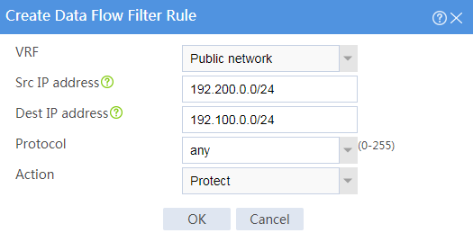
# Configure the data flow filter rules as follows:
Click Create.
Set the source IP address as 192.200.0.0/24.
Set the destination IP address as 192.100.0.0/24.
# Click OK.
Figure 9 Creating a data flow filter rule
# Set the IPsec SA triggering mode to Traffic-based.
# Configure the IPsec advanced settings as follows:
Select the Tunnel encapsulation mode.
Select the ESP security protocol.
# Click OK.
Verify that Device A and Device B can communicate with each other.
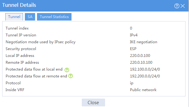
On Device A, display IPsec tunnel information:
# On the top navigation bar, click Network.
# From the navigation pane, select VPN > IPsec > IPsec Tunnels. The established IPsec tunnel is displayed.
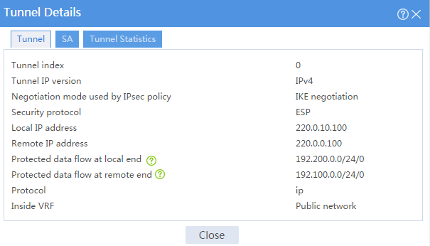
# Click the Details icon for the IPsec tunnel. The Tunnel Details page displays tunnel information, SA information, and tunnel statistics.
Figure 10 Details of the IPsec tunnel on Device A
On Device B, display IPsec tunnel information:
# On the top navigation bar, click Network.
# From the navigation pane, select VPN > IPsec > IPsec Tunnels. The established IPsec tunnel is displayed.
# Click the Details icon for the IPsec tunnel. The Tunnel Details page displays tunnel information, SA information, and tunnel statistics.
Figure 11 Details of the IPsec tunnel on Device B