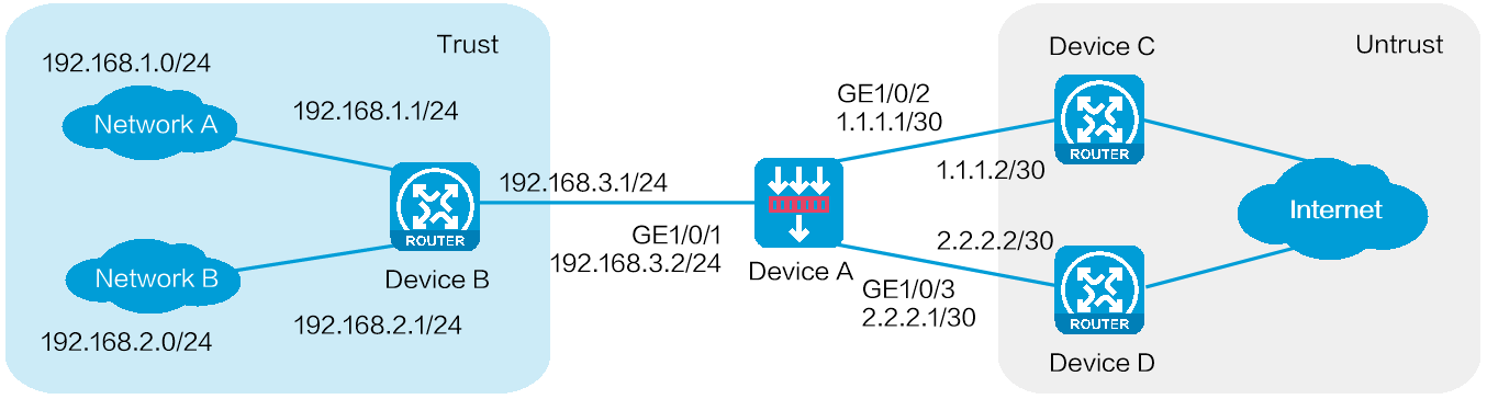
As shown in Figure 1, an enterprise deploys a security gateway Device A that is connected to internal networks A (192.168.1.0/24) and B (192.168.2.0/24) and ISP links A and B. ISP link A is connected to access device C with access point IP address 1.1.1.2/30. ISP link B is connected to access device D with access point IP address 2.2.2.2/30. Configure PBR to meet the following requirements:
Users in network A access the external network through ISP link A, and users in network B access the external network through ISP link B.
When one of the ISP links fails, user traffic from the internal network can be forwarded through the other ISP link.
This configuration example was created and verified on E8371 of the F5000-AI160 device.
Assign IP addresses to interfaces and add the interfaces to security zones.
# On the top navigation bar, click Network.
# From the navigation pane, select Interface Configuration > Interfaces.
# Click the Edit icon for GE 1/0/1.
# In the dialog box that opens, configure the IP address and security zone settings:
Select the Trust security zone.
Enter the IP address and mask of the interface. In this example, enter 192.168.3.2/24.
Use default settings for other parameters.
# Configure the IP address and security zone settings for GE 1/0/2:
Select the Untrust security zone.
Enter the IP address and mask of the interface. In this example, enter 1.1.1.1/30.
Use default settings for other parameters.
# Configure the IP address and security zone settings for GE 1/0/3:
Select the Untrust security zone.
Enter the IP address and mask of the interface. In this example, enter 2.2.2.1/30.
Use default settings for other parameters.
# Click OK.
Configure static routes:
You can configure a dynamic routing protocol based on network requirements. This example uses static routes as an example.
# On the top navigation bar, click Network.
# From the navigation pane, select Routing > Static Routing.
# On the IPv4 Static Routing tab, click Create.
# In the dialog box that opens, configure the following parameters for the static route to access network A:
Enter the destination IP address 192.168.1.0.
Specify the mask length as 24.
Specify the next hop IP address as 192.168.3.1.
Use default settings for other parameters.
# Click OK.
# Configure the following parameters for the static route to access network B:
Enter the destination IP address 192.168.2.0.
Specify the mask length as 24.
Specify the next hop IP address as 192.168.3.1.
Use default settings for other parameters.
# Click OK.
Create a security policy.
# On the top navigation bar, click Policies.
# From the navigation pane, select Security Policies > Security Policies.
# Select Create > Create a policy.
# In the dialog box that opens, configure security policy secpolicy:
Specify the source zone as Trust.
Specify the destination zone as Untrust.
Select the IPv4 type.
Specify the action as Permit.
Specify source IPv4 addresses 192.168.1.0/24 and 192.168.2.0/24.
Use default settings for other parameters.
# Click OK.
Create ACLs.
# On the top navigation bar, click Objects.
# From the navigation pane, select ACL > IPv4.
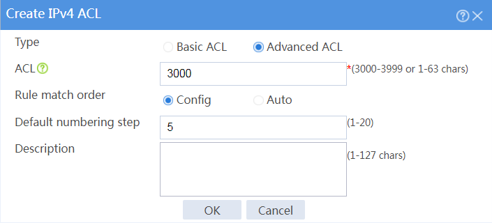
# Select Create to create an ACL to match user traffic from network A to the external network, as shown in Figure 2.
# Click OK, and then add ACL rules, as shown in Figure 3 and Figure 4.
Figure 3 Adding rules to ACL 3000
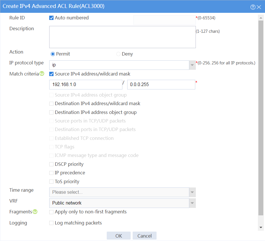
Figure 4 Adding rules to ACL 3000
# Click OK.
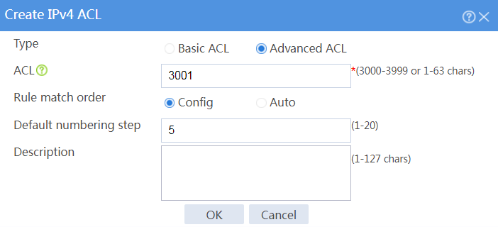
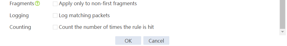
# Click Create to create an ACL to match user traffic from network B to the external network, as shown in Figure 5.
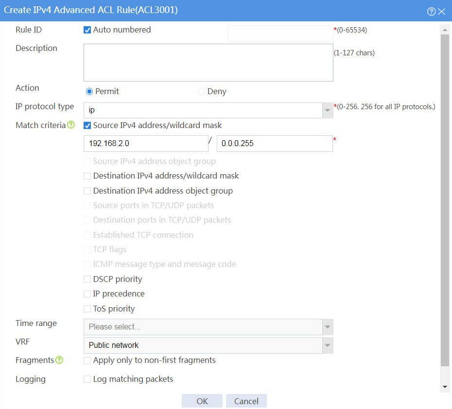
# Click OK, and then add ACL rules, as shown in Figure 6 and Figure 7.
Figure 6 Adding rules to ACL 3001

Figure 7 Adding rules to ACL 3001
# Click OK.
Configure PBR:
# On the top navigation bar, click Network.
# From the navigation pane, select Routing > PBR > IPv4 PBR.
# Click Create.
# In the dialog box that opens, configure the following parameters for the IPv4 PBR policy, as shown in Figure 8.
Figure 8 Creating an IPv4 PBR policy
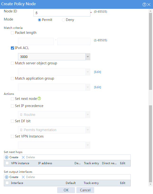
# Click Create to create policy node 5 to forward user traffic from network A to the external network, as shown in Figure 9.
Figure 9 Creating policy node 5
# Click Create in the Set next hops area, and configure the next hop settings as shown in Figure 10.
Figure 10 Setting the next hop
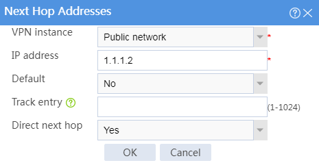
# Click OK to complete the next hop configuration.
# Click OK to complete the policy node configuration.
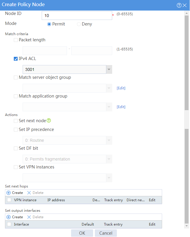
# Click Create to create policy node 10 to forward user traffic from network B to the external network, as shown in Figure 11.
Figure 11 Creating policy node 10
# Click Create in the Set next hops area, and configure the next hop settings as shown in Figure 12.
Figure 12 Setting the next hop
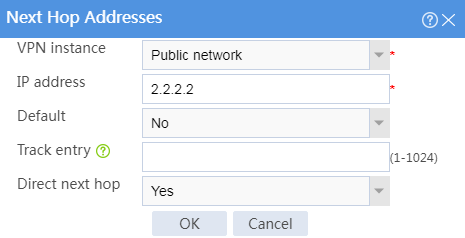
# Click OK to complete the next hop configuration.
# Click OK to complete the policy node configuration.
# Click OK to complete the IPv4 PBR policy configuration.
# Configure a static route to ensure that packets from the internal network to the external network can be forwarded to GE 1/0/1 on Device A. (Details not shown.)
Use the tracert command to identify the path from a host in internal network A to external network IP address 3.3.3.3. Hop 3 is the access point IP address 1.1.1.2 of ISP link A.
The path to 3.3.3.3 has a maximum of 30 hops.
1 1 ms 1 ms 1 ms 192.168.1.1
2 2 ms 2 ms 2 ms 192.168.3.2
3 4 ms 7 ms 6 ms 1.1.1.2
4 5 ms 5 ms 4 ms 3.3.3.3
Traceroute completed.
Use the tracert command to identify the path from a host in internal network B to external network IP address 3.3.3.3. Hop 3 is the access point IP address 2.2.2.2 of ISP link B.
The path to 3.3.3.3 has a maximum of 30 hops.
1 1 ms 1 ms 1 ms 192.168.2.1
2 2 ms 2 ms 2 ms 192.168.3.2
3 5 ms 6 ms 5 ms 2.2.2.2
4 6 ms 4 ms 5 ms 3.3.3.3
Traceroute completed.