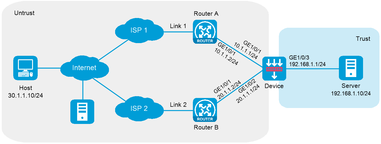
As shown in Figure 1, ISP 1 and ISP 2 provide an enterprise with two links, Link 1 and Link 2. Both links have the same router hop count, bandwidth, and cost.
Configure inbound link load balancing for the device to select an optimal link for traffic from the client host to the server.
Figure 1 Network diagram
This configuration example was created and verified on E8371 of the F5000-AI160 device.
Assign IP addresses to interfaces and add the interfaces to security zones.
# On the top navigation bar, click the Network tab.
# From the navigation pane, select Interface Configuration > Interfaces.
# Click the Edit icon for GE 1/0/1.
# In the dialog box that opens, configure the interface:
Select the Untrust security zone.
On the IPv4 Address tab, enter the IP address and mask length of the interface. In this example, enter 10.1.1.1/24.
Use the default settings for other parameters.
Click OK.
# Add GE 1/0/2 to the Untrust security zone and set its IP address to 20.1.1.1./24 in the same way you configure GE 1/0/1.
# Add GE 1/0/3 to the Trust security zone and set its IP address to 192.168.1.1/24 in the same way you configure GE 1/0/1.
Configure security policies.
# On the top navigation bar, click Policies.
# From the navigation pane, select Security Policies > Security Policies.
# Click Create.
# In the dialog box that opens, configure a security policy named Untrust-to-Trust:
Enter policy name Untrust-to-Trust.
Select type IPv4.
Select source zone Untrust.
Select destination zone Trust.
Enter destination IPv4 address 192.168.1.0/24.
Select action Permit.
Use the default settings for other parameters.
Click OK.
# Configure a security policy named Local-to-Untrust:
Enter policy name Local-to-Untrust.
Select type IPv4.
Select source zone Local.
Select destination zone Untrust.
Enter destination IPv4 addresses 10.1.1.0/24 and 20.1.1.0/24.
Select action Permit.
Use the default settings for other parameters.
Click OK.
Configure an ICMP probe template.
# On the top navigation bar, click Objects.
# From the navigation pane, click Health Monitoring.
# Click Create.
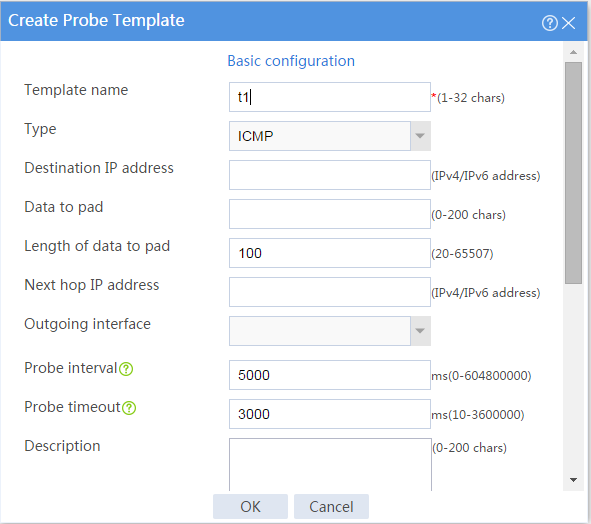
# In the dialog box that opens, configure an ICMP probe template:
Enter template name t1.
Select type ICMP.
Enter 100 for the Length of data to pad field.
Enter 5000 for the Probe interval field.
Enter 3000 for the Probe timeout field.
Click OK.
Figure 2 Creating an ICMP probe template
Configure links.
# On the top navigation bar, click Objects.
# From the navigation pane, select Load Balancing > Links.
# Click Create.
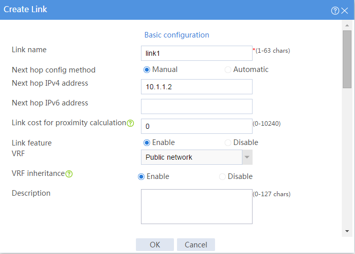
# In the dialog box that opens, configure a link named link1:
Basic configuration:
Enter link name link1.
Select Manual for the Next hop config method field.
Enter next hop IPv4 address 10.1.1.2.
Enable the link feature.
Enable VRF inheritance.
Figure 3 Creating link link1 (basic configuration)
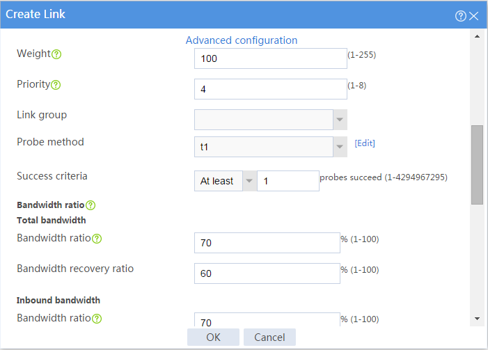
Advanced configuration:
Enter weight 100.
Enter priority 4.
Select probe method t1.
Set the success criteria to At least 1.
Enter total bandwidth ratio 70%.
Enter bandwidth recovery ratio 60%.
Enter inbound bandwidth ratio 70%.
Click OK.
Figure 4 Creating link link1 (advanced configuration)
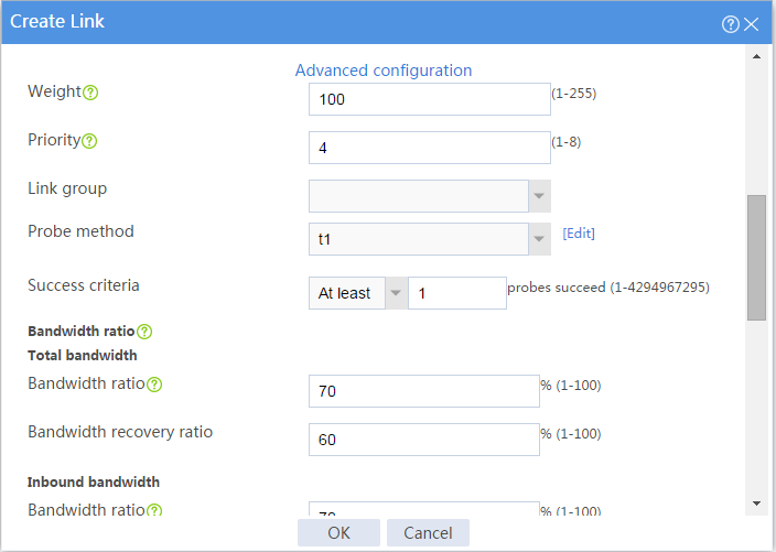
# Configure link link2 in the same way you configure link link1.
Figure 5 Creating link link2 (basic configuration)
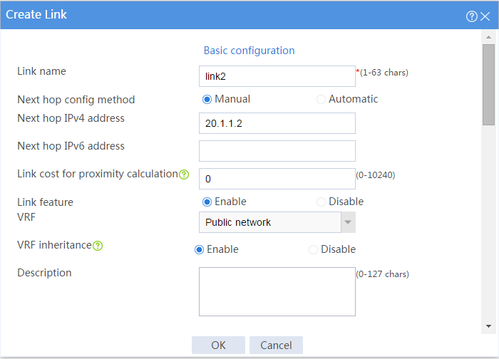
Figure 6 Creating link link2 (advanced configuration)
Configure a real server.
# On the top navigation bar, click Polices.
# From the navigation pane, select Server Load Balancing > Real Servers.
# Click Create.
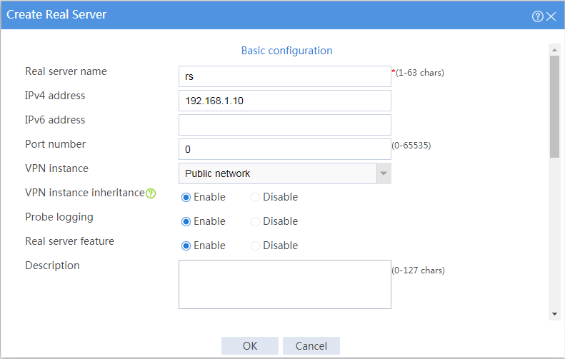
# In the dialog box that opens, configure a real server named rs:
Enter server name rs.
Enter IPv4 address 192.168.1.10.
Enter port number 0.
Enable VRF inheritance.
Enable the real server.
Click OK.
Figure 7 Creating real server rs
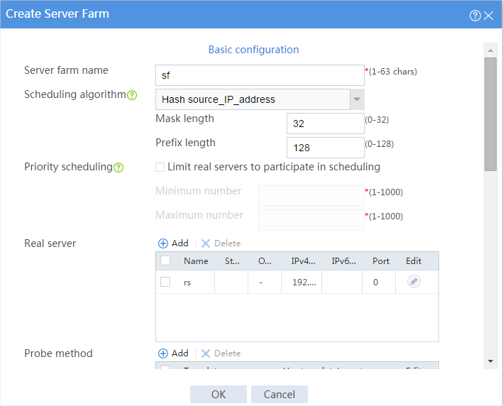
Configure a server farm.
# On the top navigation bar, click Polices.
# From the navigation pane, select Server Load Balancing > Server Farms.
# Click Create.
# In the dialog box that opens, configure a server farm named sf:
Enter server farm name sf.
Select scheduling algorithm Hash source_IP_address.
Enter mask length 32 and prefix length 128.
Add real server rs to the server farm.
Select probe method t1.
Click OK.
Figure 8 Creating server farm sf
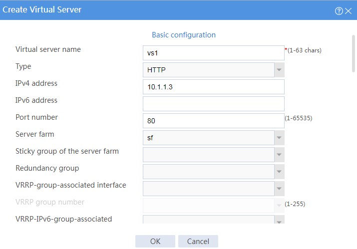
Configure virtual servers.
# On the top navigation bar, click Polices.
# From the navigation pane, select Server Load Balancing > Virtual Servers.
# Click Create.
# In the dialog box that opens, configure a virtual server named vs1:
Enter server name vs1.
Select type HTTP.
Enter IPv4 address 10.1.1.3.
Enter port number 80.
Select server farm sf.
Disable IP address advertisement.
Enable sticky entry synchronization.
Enable the virtual server.
Click OK.
Figure 9 Creating virtual server vs1
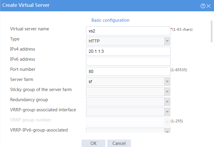
# Configure virtual server vs2 in the same way you configure virtual server vs1.
Figure 10 Creating virtual server vs2
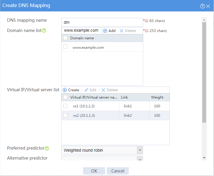
Configure a DNS mapping.
# On the top navigation bar, click Polices.
# From the navigation pane, select Link Load Balancing > Inbound Link LB.
# On the DNS Mapping tab, click Create.
# In the dialog box that opens, configure a DNS mapping named dm:
Enter DNS mapping name dm.
Select virtual IP pool vsp.
Add domain name www.example.com to the domain name list.
Set the TTL to 3600 seconds.
Enable DNS mapping.
Click OK.
Figure 11 Creating DNS mapping dm
Configure DNS listeners.
# On the top navigation bar, click Polices.
# From the navigation pane, select Link Load Balancing > Inbound Link LB.
# On the DNS Listener tab, click Create.
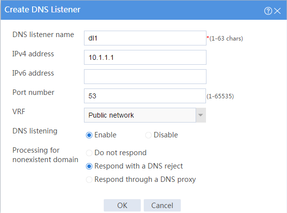
# In the dialog box that opens, configure a DNS listener named dl1:
Enter DNS listener name dl1.
Enter IPv4 address 10.1.1.1.
Enter port number 53.
Enable DNS listening.
Select Respond with a DNS reject for the Processing for nonexistent domain field.
Click OK.
Figure 12 Creating DNS listener d1
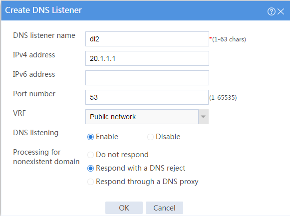
# Configure DNS listener dl2 in the same way you configure DNS listener dl1.
Figure 13 Creating DNS listener dl2
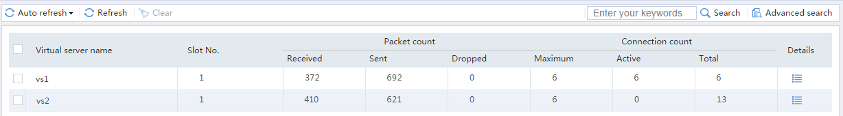
Access http://www.example.com through the browser on the host, and verify that the device distributes the HTTP requests to the links link1 and link2.
# On the top navigation bar, click the Monitor tab.
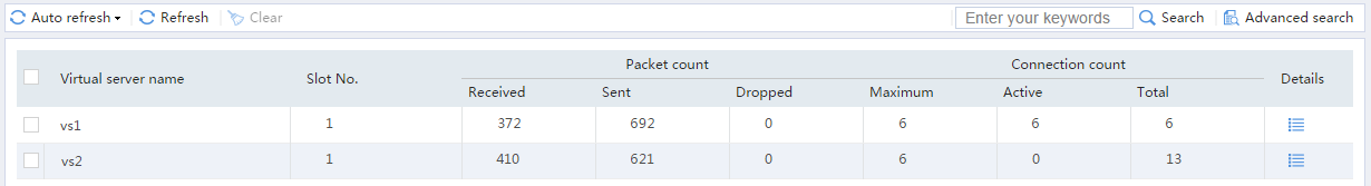
# From the navigation pane, select Statistics > Server LB Statistics > Virtual Servers.
The Virtual Server Statistics page is as follows:
Figure 14 Virtual Server statistics
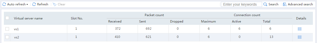
Disable virtual server vs1, access http://www.example.com through the browser on the host, and verify that the device distributes the HTTP requests to only link link2.
# On the top navigation bar, click the Monitor tab.
# From the navigation pane, select Statistics > Server LB Statistics > Virtual Servers.
The Virtual Server Statistics page is as follows:
Figure 15 Virtual Server statistics
Disable virtual server vs2, access http://www.example.com through the browser on the host, and verify that the device distributes the HTTP requests to only link link1.
# On the top navigation bar, click the Monitor tab.
# From the navigation pane, select Statistics > Server LB Statistics > Virtual Servers.
The Virtual Server Statistics page is as follows:
Figure 16 Virtual Server statistics