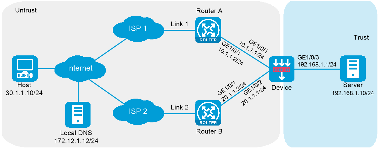
In Figure 1, ISP 1 and ISP 2 provide two links, Link 1 and Link 2, with the same router hop count, bandwidth, and cost. The internal server uses domain name l.example.com to provide services. The actual host name of the internal server is www.example.com.
Configure inbound link load balancing for the device to select an available link for traffic from the client host to the internal server when a link fails.
This configuration example was created and verified on F5000-AI160-E8371.
1. Assign IP addresses to interfaces:
# Assign an IP address to interface GigabitEthernet 1/0/1.
<Device> system-view
[Device] interface gigabitethernet 1/0/1
[Device-GigabitEthernet1/0/1] ip address 10.1.1.1 255.255.255.0
[Device-GigabitEthernet1/0/1] quit
# Assign IP addresses to other interfaces in the same way. (Details not shown.)
2. Add interfaces to security zones.
[Device] security-zone name untrust
[Device-security-zone-Untrust] import interface gigabitethernet 1/0/1
[Device-security-zone-Untrust] import interface gigabitethernet 1/0/2
[Device-security-zone-Untrust] quit
[Device] security-zone name trust
[Device-security-zone-Trust] import interface gigabitethernet 1/0/3
[Device-security-zone-Trust] quit
3. Configure a security policy:
Configure rules to permit traffic from the Untrust security zone to the Trust security zone and traffic between the Untrust and Local security zones, so the users can access the server:
# Configure a rule named lbrule1 to allow the users to access the server.
[Device] security-policy ip
[Device-security-policy-ip] rule name lbrule1
[Device-security-policy-ip-1-lbrule1] source-zone untrust
[Device-security-policy-ip-1-lbrule1] destination-zone trust
[Device-security-policy-ip-1-lbrule1] destination-ip-subnet 192.168.1.0 255.255.255.0
[Device-security-policy-ip-1-lbrule1] action pass
[Device-security-policy-ip-1-lbrule1] quit
# Configure a rule named lblocalin to allow the users to access the DNS listener.
[Device-security-policy-ip] rule name lblocalin
[Device-security-policy-ip-2-lblocalout] source-zone untrust
[Device-security-policy-ip-2-lblocalout] destination-zone local
[Device-security-policy-ip-2-lblocalout] destination-ip-subnet 10.1.1.1 255.255.255.255
[Device-security-policy-ip-2-lblocalout] destination-ip-subnet 20.1.1.1 255.255.255.255
[Device-security-policy-ip-2-lblocalout] action pass
[Device-security-policy-ip-2-lblocalout] quit
# Configure a rule named lblocalout to allow the device to send probe packets to the next hop.
[Device-security-policy-ip] rule name lblocalout
[Device-security-policy-ip-3-lblocalout] source-zone local
[Device-security-policy-ip-3-lblocalout] destination-zone untrust
[Device-security-policy-ip-3-lblocalout] destination-ip-subnet 10.1.1.0 255.255.255.0
[Device-security-policy-ip-3-lblocalout] destination-ip-subnet 20.1.1.0 255.255.255.0
[Device-security-policy-ip-3-lblocalout] action pass
[Device-security-policy-ip-3-lblocalout] quit
[Device-security-policy-ip] quit
4. Configure LB links:
# Create the ICMP-type NQA template t1.
[Device] nqa template icmp t1
[Device-nqatplt-icmp-t1] quit
# Create the LB link link1, and specify the outbound next hop as 10.1.1.2 and health monitoring method as t1 for the LB link.
[Device] loadbalance link link1
[Device-lb-link-link1] router ip 10.1.1.2
[Device-lb-link-link1] probe t1
[Device-lb-link-link1] quit
# Create the LB link link2, and specify the outbound next hop as 20.1.1.2 and health monitoring method as t1 for the LB link.
[Device] loadbalance link link2
[Device-lb-link-link2] router ip 20.1.1.2
[Device-lb-link-link2] probe t1
[Device-lb-link-link2] quit
5. Create the server farm sf.
[Device] server-farm sf
[Device-sfarm-sf] quit
6. Create the real server rs with the IPv4 address 192.168.1.10, and add it to the server farm sf.
[Device] real-server rs
[Device-rserver-rs] ip address 192.168.1.10
[Device-rserver-rs] server-farm sf
[Device-rserver-rs] quit
7. Configure virtual servers:
# Create the HTTP virtual server vs1 with the VSIP 10.1.1.3 and port number 80, specify its default master server farm sf, and enable the virtual server.
[Device] virtual-server vs1 type http
[Device-vs-http-vs1] virtual ip address 10.1.1.3
[Device-vs-http-vs1] port 80
[Device-vs-http-vs1] default server-farm sf
[Device-vs-http-vs1] service enable
[Device-vs-http-vs1] quit
# Create the HTTP virtual server vs2 with the VSIP 20.1.1.3 and port number 80, specify its default master server farm sf, and enable the virtual server.
[Device] virtual-server vs2 type http
[Device-vs-http-vs2] virtual ip address 20.1.1.3
[Device-vs-http-vs2] port 80
[Device-vs-http-vs2] default server-farm sf
[Device-vs-http-vs2] service enable
[Device-vs-http-vs2] quit
8. Create the virtual server pool vsp, and add the virtual servers vs1 and vs2 associated with the LB links link1 and link2 to the virtual server pool.
[Device] loadbalance virtual-server-pool vsp
[Device-lb-vspool-vsp] virtual-server vs1 link link1
[Device-lb-vspool-vsp] virtual-server vs2 link link2
[Device-lb-vspool-vsp] quit
9. Configure DNS listeners:
# Create the DNS listener dl1 with the IP address 10.1.1.1, and enable the DNS listener feature.
[Device] loadbalance dns-listener dl1
[Device-lb-dl-dl1] ip address 10.1.1.1
[Device-lb-dl-dl1] service enable
[Device-lb-dl-dl1] quit
# Create the DNS listener dl2 with the IP address 20.1.1.1, and enable the DNS listener feature.
[Device] loadbalance dns-listener dl2
[Device-lb-dl-dl2] ip address 20.1.1.1
[Device-lb-dl-dl2] service enable
[Device-lb-dl-dl2] quit
10. Create the DNS mapping dm, specify the domain name www.example.com and virtual server pool vsp for the DNS mapping, and enable the DNS mapping feature.
[Device] loadbalance dns-map dm
[Device-lb-dm-dm] domain-name www.example.com
[Device-lb-dm-dm] service enable
[Device-lb-dm-dm] virtual-server-pool vsp
[Device-lb-dm-dm] quit
11. Configure a DNS forward zone:
# Create a DNS forward zone with domain name example.com.
[Device] loadbalance zone example.com
# Configure a CNAME resource record by specifying alias l.example.com for host name www.example.com.
[Device-lb-zone-example.com] record cname alias l.example.com. canonical www.example.com. ttl 600
[Device-lb-zone-example.com] quit
# Display information about all DNS listeners.
[Device] display loadbalance dns-listener
DNS listener name: dl1
Service state: Enabled
IPv4 address: 10.1.1.1
Port: 53
IPv6 address: --
IPv6 Port: 53
Fallback: Reject
VPN instance:
# Display information about all DNS mappings.
[Device] display loadbalance dns-map
DNS mapping name: dm
Service state: Enabled
TTL: 3600
Domain name list: www.example.com
Virtual server pool: vsp
# Display information about all DNS forward zones.
[Device] display loadbalance zone
Zone name: example.com
TTL: 3600s
SOA:
Record list:
Type TTL RDATA
CNAME 600s l.example.com. www.example.com.
# Display brief information about all virtual server pools.
[Device] display loadbalance virtual-server-pool brief
Predictor: RR - Round robin, RD - Random, LC - Least connection,
TOP - Topology, PRO - Proximity
BW - Bandwidth, MBW - Max bandwidth,
IBW - Inbound bandwidth, OBW - Outbound bandwidth,
MIBW - Max inbound bandwidth, MOBW - Max outbound bandwidth,
HASH(SIP) - Hash address source IP,
HASH(DIP) - Hash address destination IP,
HASH(SIP-PORT) - Hash address source IP-port
VSpool Pre Alt Fbk BWP Total Active
vsp RR LC Enabled 0 0
# Display detailed information about all virtual server pools.
[Device] display loadbalance virtual-server-pool
Virtual-server pool: local_pool
Predictor:
Preferred RR
Alternate --
Fallback --
Bandwidth busy-protection: Disabled
Total virtual servers: 2
Active virtual servers: 2
Virtual server list:
Name State Address Port Weight Link
vs1 Active 10.1.1.3 80 100 link1
vs2 Active 20.1.1.3 80 100 link2
# Display brief information about all real servers.
[Device] display real-server brief
Real server Address Port State VPN instance Server farm
rs 192.168.1.10 0 Active sf
# Display brief information about all LB links.
[Device] display loadbalance link brief
link Router IP State VPN instance Link group
link1 10.1.1.2 Active
link2 20.1.1.2 Probe-failed
# Display detailed information about all server farms.
[Device] display server-farm
Server farm: sf
Description:
Predictor: Round robin
Proximity: Enabled
NAT: Enabled
SNAT pool:
Failed action: Keep
Active threshold: Disabled
Slow-online: Disabled
Probe information:
Probe success criteria: All
Probe method:
t1
Selected server: Disabled
Probe information:
Probe success criteria: All
Probe method:
t1
Total real server: 1
Active real server: 1
Real server list:
Name State VPN instance Address Port Weight Priority
rs Active 192.168.1.10 0 100 4
# Display brief information about all virtual servers.
[Device] display virtual-server brief
Virtual server State Type VPN instance Virtual address Port
vs1 Active HTTP 10.1.1.3 80
vs2 Active HTTP 20.1.1.3 80
After you complete the previous configuration, domain name l.example.com can be resolved into 10.1.1.1 or 20.1.1.1. The client host can access the internal server through Link 1 or Link 2.
#
interface GigabitEthernet1/0/1
ip address 10.1.1.1 255.255.255.0
#
interface GigabitEthernet1/0/2
ip address 20.1.1.2 255.255.255.0
#
interface GigabitEthernet1/0/3
ip address 192.168.1.1 255.255.255.0
#
security-zone name Trust
import interface GigabitEthernet1/0/3
#
security-zone name Untrust
import interface GigabitEthernet1/0/1
import interface GigabitEthernet1/0/2
#
security-policy ip
rule 1 name lbrule1
action pass
source-zone untrust
destination-zone trust
destination-ip-subnet 192.168.1.0 255.255.255.0
rule 2 name lblocalin
action pass
source-zone untrust
destination-zone local
destination-ip-host 10.1.1.1
destination-ip-host 20.1.1.1
rule 3 name lblocalout
action pass
source-zone local
destination-zone untrust
destination-ip-subnet 10.1.1.0 255.255.255.0
destination-ip-subnet 20.1.1.0 255.255.255.0
#
nqa template icmp t1
#
loadbalance link link1
router ip 10.1.1.2
probe t1
#
loadbalance link link2
router ip 20.1.1.2
probe t1
#
server-farm sf
#
real-server rs
ip address 192.168.1.10
server-farm sf
#
virtual-server vs1 type http
virtual ip address 10.1.1.3
default server-farm sf
service enable
#
virtual-server vs2 type http
virtual ip address 20.1.1.3
default server-farm sf
service enable
#
loadbalance virtual-server-pool vsp
virtual-server vs1 link link1
virtual-server vs2 link link2
#
loadbalance dns-listener dl1
ip address 10.1.1.1
service enable
#
loadbalance dns-listener dl2
ip address 20.1.1.1
service enable
#
loadbalance dns-map dm
domain-name www.example.com
service enable
virtual-server-pool vsp
#
loadbalance zone example.com
record cname alias l.example.com. canonical www.example.com. ttl 600