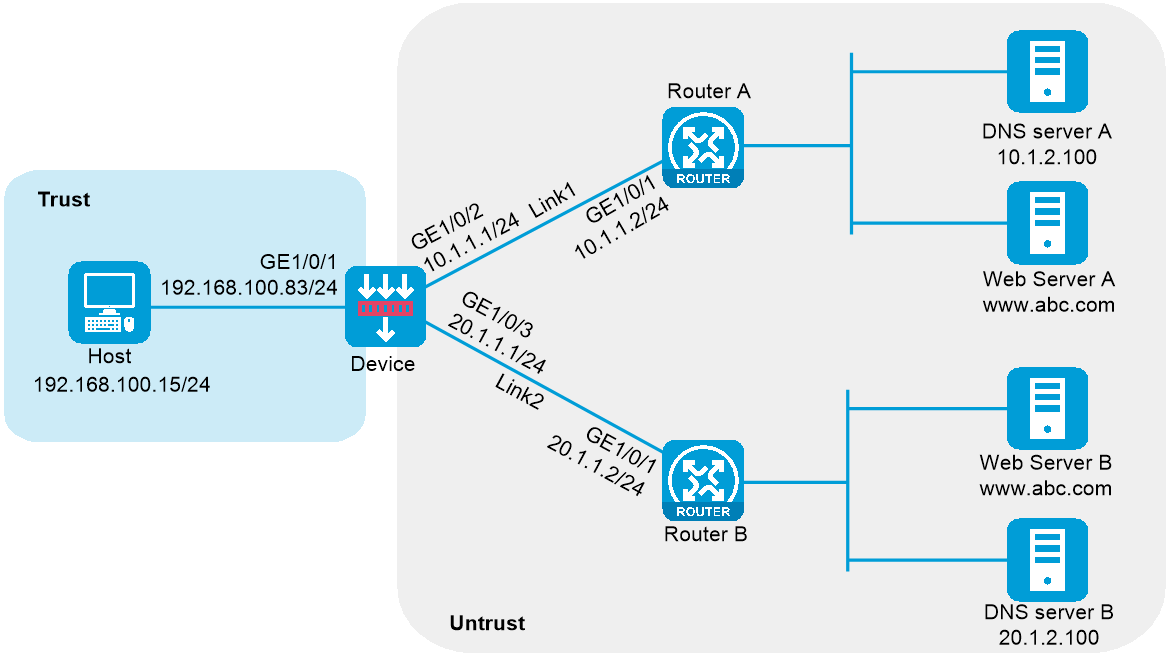
As shown in Figure 1, ISP 1 and ISP 2 provide two links with the same bandwidth to an enterprise: Link 1 and Link 2. The DNS server IP address of ISP 1 is 10.1.2.100. The DNS server IP address of ISP 2 is 20.1.2.100. Intranet users use domain name www.example.com to access Web server A and Web server B.
Configure a transparent DNS proxy on the device to evenly distribute user traffic to Link 1 and Link 2.
Figure 1 Network diagram
This configuration example was created and verified on E8371 of the F5000-AI160 device.
Assign IP addresses to interfaces and add the interfaces to security zones.
# On the top navigation bar, click the Network tab.
# From the navigation pane, select Interface Configuration > Interfaces.
# Click the Edit icon for GE 1/0/1.
# In the dialog box that opens, configure the interface:
Select the Trust security zone.
On the IPv4 Address tab, enter the IP address and mask length of the interface. In this example, enter 192.168.100.83/24.
Use the default settings for other parameters.
Click OK.
# Add GE 1/0/2 to the Untrust security zone and set its IP address to 10.1.1.1/24 in the same way you configure GE 1/0/1.
# Add GE 1/0/3 to the Untrust security zone and set its IP address to 20.1.1.1/24 in the same way you configure GE 1/0/1.
Configure security policies.
# On the top navigation bar, click Policies.
# From the navigation pane, select Security Policies > Security Policies.
# Click Create.
# In the dialog box that opens, configure a security policy named Trust-to-Untrust:
Enter policy name Trust-to-Untrust.
Select type IPv4.
Select source zone Trust.
Enter source IPv4 address 192.168.100.0/24.
Select destination zone Untrust.
Select action Permit.
Use the default settings for other parameters.
Click OK.
# Configure a security policy named Local-to-Untrust:
Enter policy name Local-to-Untrust.
Select type IPv4.
Select source zone Local.
Select destination zone Untrust.
Enter destination IPv4 addresses 10.1.1.0/24 and 20.1.1.0/24.
Select action Permit.
Use the default settings for other parameters.
Click OK.
Configure an ICMP probe template.
# On the top navigation bar, click Objects.
# From the navigation pane, click Health Monitoring.
# Click Create.
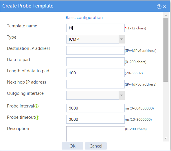
# In the dialog box that opens, configure an ICMP probe template:
Enter template name t1.
Select type ICMP.
Enter 100 for the Length of data to pad field.
Enter 5000 for the Probe interval field.
Enter 3000 for the Probe timeout field.
Use the default settings for other parameters.
Click OK.
Figure 2 Creating an ICMP probe template
Configure links.
# On the top navigation bar, click Objects.
# From the navigation pane, select Load Balancing > Links.
# Click Create.
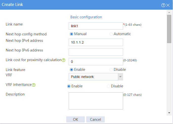
# In the dialog box that opens, configure a link named link1:
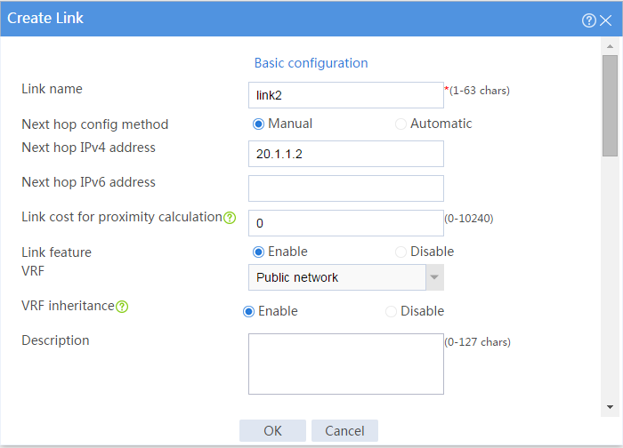
Enter link name link1.
Select Manual for the Next hop config method field.
Enter next hop IPv4 address 10.1.1.2.
Set the link cost for proximity calculation to 0.
Enable the link feature.
Enable VRF inheritance.
Click OK.
Figure 3 Creating link link1
# Configure link link2 in the same way you configure link link1.
Figure 4 Creating link link2
Configure DNS servers.
# On the top navigation bar, click Polices.
# From the navigation pane, select Link Load Balancing > DNS Proxy.
# On the DNS Server tab, click Create.
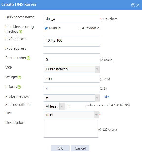
# In the dialog box that opens, configure a DNS server named dns_a:
Enter DNS server name dns_a.
Select Manual for the IP address config method field.
Enter IPv4 address 10.1.2.100.
Enter port number 0.
Enter weight 100.
Enter priority 4.
Select probe method t1.
Set the success criteria to At least 1.
Select link link1.
Click OK.
Figure 5 Creating DNS server dns_a
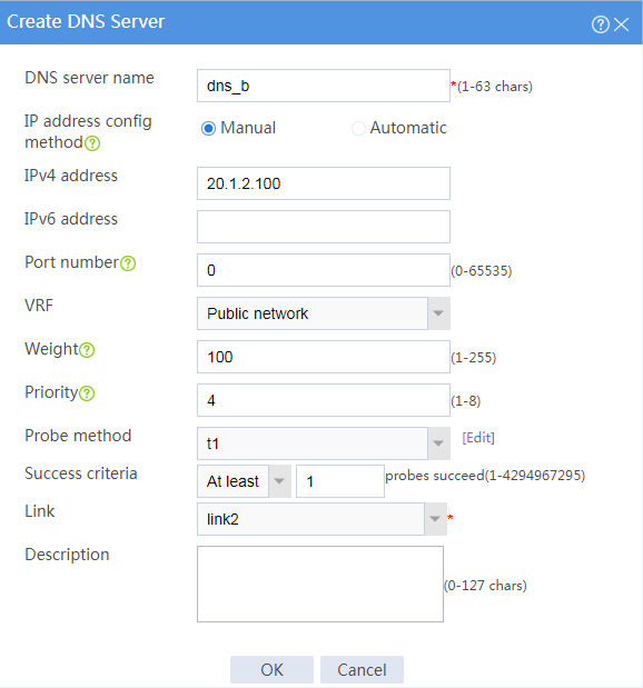
# Configure DNS server dns_b in the same way you configure DNS server dns_a.
Figure 6 Creating DNS server dns_b
Configure a DNS server pool.
# On the top navigation bar, click Polices.
# From the navigation pane, select Link Load Balancing > DNS Proxy.
# On the DNS Server Pool tab, click Create.
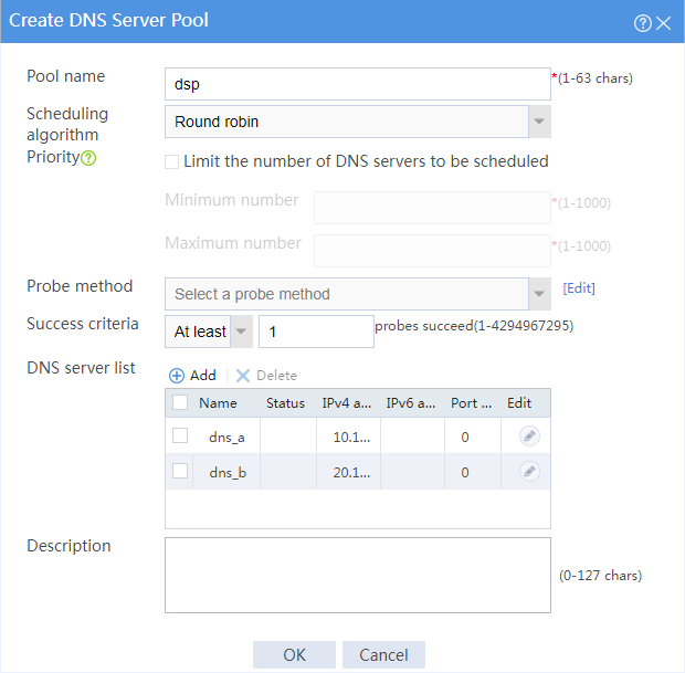
# In the dialog box that opens, configure a DNS server pool named dsp:
Enter DNS server pool name dsp.
Select scheduling algorithm Round robin.
Set the success criteria to At least 1.
Add DNS servers dns_a and dns_b to the DNS server pool.
Click OK.
Figure 7 Creating DNS server pool dsp
Configure IPv4 routing policies.
# On the top navigation bar, click Polices.
# From the navigation pane, select Link Load Balancing > DNS Proxy.
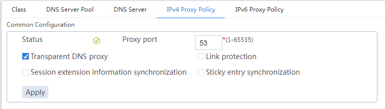
# In the Common configuration area on the IPv4 Routing Policy tab, select the Transparent DNS proxy option and click Apply.
Figure 8 Common configuration
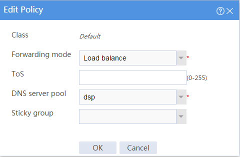
# In the Policy area on the IPv4 Routing Policy tab, click the Edit icon for the default IPv4 routing policy named Default.
# In the dialog box that opens, configure the default IPv4 routing policy:
Select forwarding mode Load balance.
Select DNS server pool dsp.
Click OK.
Figure 9 Editing the default IPv4 routing policy
Access http://www.example.com through the browser on the host, and verify that the device distributes the DNS requests to DNS servers dns_a and dns_b.
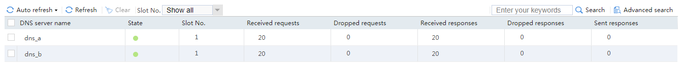
View the DNS Server Statistics page.
# On the top navigation bar, click the Monitor tab.
# From the navigation pane, select Statistics > DNS Proxy Statistics > DNS Servers.
The DNS Server Statistics page is as follows:
Figure 10 DNS server statistics
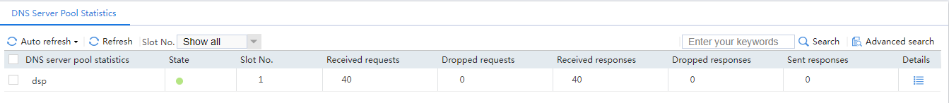
View the DNS Server Pool Statistics page.
# From the navigation pane, select Statistics > DNS Proxy Statistics > DNS Server Pools.
The DNS Server Pool Statistics page is as follows:
Figure 11 DNS server pool statistics