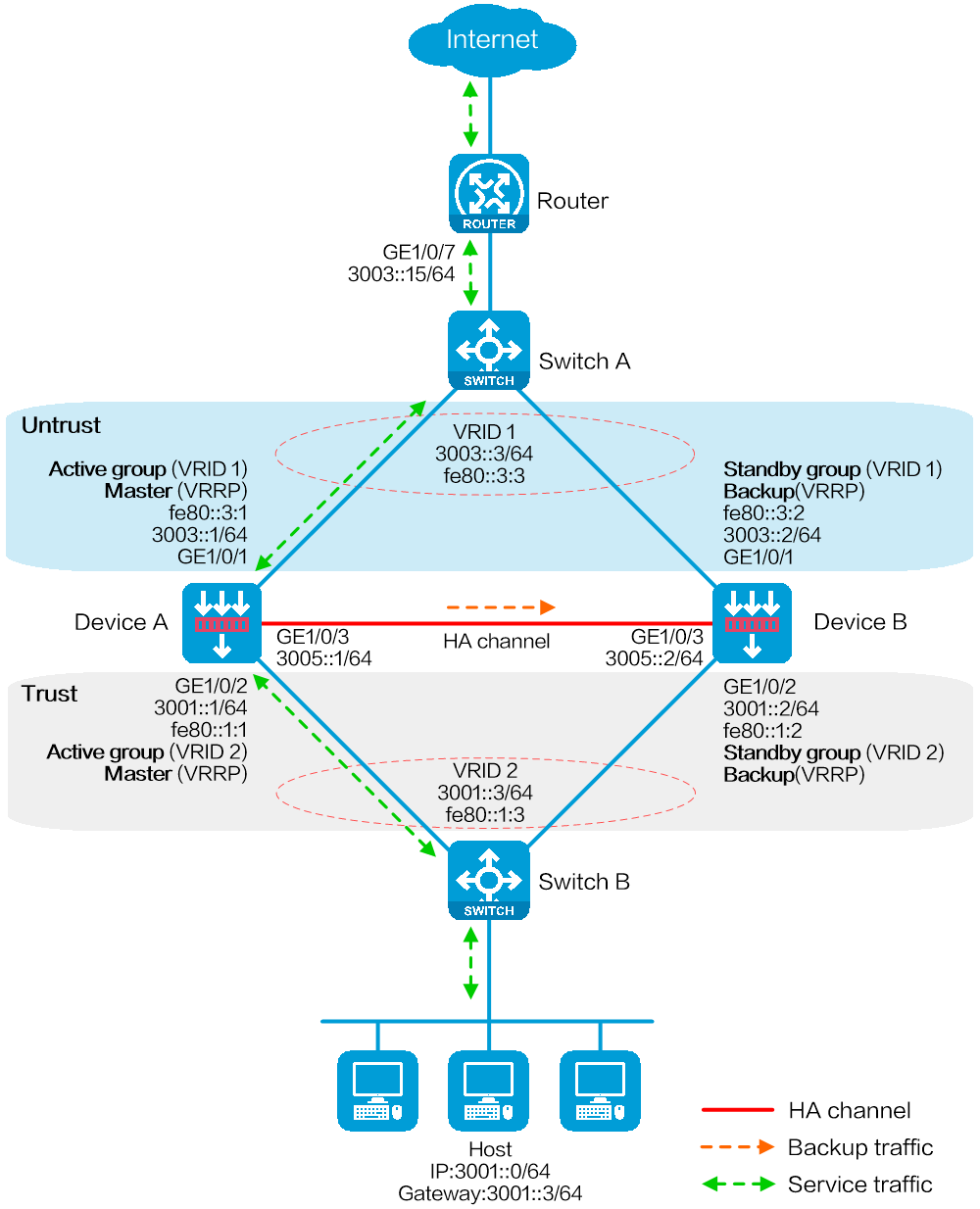
As shown in Figure 1, set up a hot backup system at the border between the Internet and the internal network of an enterprise to ensure service continuity.
Configure hot backup to collaborate with VRRP.
Configure the hot backup system to operate in active/standby mode.
Configure Device A and Device B as the primary device and the secondary device, respectively.
This configuration example was created and verified on E8371 of the F5000-AI160 device.
A hot backup system can contain a maximum of two devices.
To ensure that the traffic size is within the processing capability of one device upon failure of the other device, make sure the throughput of each device does not exceed 50% of its capability.
Before you configure hot backup, verify that the following hardware settings are the same on the devices to be assigned to a hot backup system:
Device model.
Number and type of management interfaces, service interfaces, and interfaces for setting up the hot backup channels. Do not use one interface for multiple purposes.
Location, number, and type of disks. A device not with disks installed has small log storage and do not support some types of logs or reports.
Before you configure hot backup, verify that the following software settings are the same on the devices to be assigned to a hot backup system:
Software environment and version, including boot packages, system packages, feature packages, and patches.
Licensed signature libraries and features, such as signature library types, signature library version, validation time, and number of licensed resources.
Interface numbers.
Type, speed, and number of the interfaces for setting up the hot backup channels. As a best practice, use aggregate interfaces.
Aggregate interface numbers and aggregation member port numbers.
Security zone configuration on the interfaces at the same location.
Multi-CPU packet distribution policy (configurable with the forwarding policy command).
Configure IPv6 addresses for interfaces.
# Assign an IPv6 address to GigabitEthernet 1/0/7.
<Router> system-view
[Router] interface gigabitethernet 1/0/7
[Router-GigabitEthernet1/0/7] ipv6 address 3003::15/64
[Router-GigabitEthernet1/0/7] quit
# Assign IP addresses to other interfaces in the same way. (Details not shown.)
Configure routes as follows:
# Specify 3003::3/64 (virtual IPv6 address of VRRP group 1) as the next hop of the routes to the internal network.
# Specify 3007::15/64 as the next hop of the route to the Internet.
[Router] ipv6 route-static 3001::3 64 3003::3
[Router] ipv6 route-static 0::0 64 3007::15
Create VLAN 10 on Switch A, and configure the interfaces that connect Switch A to Device A, Device B, and Router as access ports, and then assign the ports to VLAN 10.
<SwitchA> system-view
[SwitchA] vlan 10
[SwitchA-vlan10] quit
[SwitchA] interface gigabitethernet 1/0/1
[SwitchA-GigabitEthernet1/0/1] port access vlan 10
[SwitchA-GigabitEthernet1/0/1] quit
[SwitchA] interface gigabitethernet 1/0/2
[SwitchA-GigabitEthernet1/0/2] port access vlan 10
[SwitchA-GigabitEthernet1/0/2] quit
[SwitchA] interface gigabitethernet 1/0/3
[SwitchA-GigabitEthernet1/0/3] port access vlan 10
[SwitchA-GigabitEthernet1/0/3] quit
Create VLAN 10 on Switch B, and configure the interfaces that connect Switch B to Device A, Device B, and Host as access ports, and then assign the ports to VLAN 10.
<SwitchB> system-view
[SwitchB] vlan 10
[SwitchB-vlan10] quit
[SwitchB] interface gigabitethernet 1/0/1
[SwitchB-GigabitEthernet1/0/1] port access vlan 10
[SwitchB-GigabitEthernet1/0/1] quit
[SwitchB] interface gigabitethernet 1/0/2
[SwitchB-GigabitEthernet1/0/2] port access vlan 10
[SwitchB-GigabitEthernet1/0/2] quit
[SwitchB] interface gigabitethernet 1/0/3
[SwitchB-GigabitEthernet1/0/3] port access vlan 10
[SwitchB-GigabitEthernet1/0/3] quit
Assign IP addresses to interfaces.
<DeviceA> system-view
[DeviceA] interface gigabitethernet 1/0/1
[DeviceA-GigabitEthernet1/0/1] ipv6 address 3003::1/64
[DeviceA-GigabitEthernet1/0/1] ipv6 address fe80::3:1 link-local
[DeviceA-GigabitEthernet1/0/1] quit
[DeviceA] interface gigabitethernet 1/0/2
[DeviceA-GigabitEthernet1/0/2] ipv6 address 3001::1/64
[DeviceA-GigabitEthernet1/0/2] ipv6 address fe80::1:1 link-local
[DeviceA-GigabitEthernet1/0/2] undo ipv6 nd ra halt
[DeviceA-GigabitEthernet1/0/2] quit
[DeviceA] interface gigabitethernet 1/0/3
[DeviceA-GigabitEthernet1/0/3] ipv6 address 3005::1/64
[DeviceA-GigabitEthernet1/0/3] ipv6 address auto link-local
[DeviceA-GigabitEthernet1/0/3] quit
Add interfaces to security zones.
[DeviceA] security-zone name untrust
[DeviceA-security-zone-Untrust] import interface gigabitethernet 1/0/1
[DeviceA-security-zone-Untrust] quit
[DeviceA] security-zone name trust
[DeviceA-security-zone-Trust] import interface gigabitethernet 1/0/2
[DeviceA-security-zone-Trust] quit
Configure settings for routing. This example configures a static route, and the next hop in the route is 3003::15.
[DeviceA] ipv6 route-static 0::0 0 3003::15
Configure a security policy.
Perform this task only on the primary device. After the HA group is set up, the secondary device automatically synchronizes its security policy configuration with the primary device.
# Configure security policy rule named trust-untrust to permit the packets from 3001::0/64 to the Internet.
[DeviceA] security-policy ipv6
[DeviceA-security-policy-ipv6] rule name trust-untrust
[DeviceA-security-policy-ipv6-0-trust-untrust] source-zone trust
[DeviceA-security-policy-ipv6-0-trust-untrust] destination-zone untrust
[DeviceA-security-policy-ipv6-0-trust-untrust] source-ip-subnet 3001::0 64
[DeviceA-security-policy-ipv6-0-trust-untrust] action pass
[DeviceA-security-policy-ipv6-0-trust-untrust] quit
# Configure rules to permit VRRP protocol packets. When the HA channel is disconnected, Device A and Device B can exchange VRRP protocol packets to elect a VRRP master.
[DeviceA-security-policy-ipv6] rule name vrrp1
[DeviceA-security-policy-ipv6-1-vrrp1] source-zone trust
[DeviceA-security-policy-ipv6-1-vrrp1] destination-zone local
[DeviceA-security-policy-ipv6-1-vrrp1] service vrrp
[DeviceA-security-policy-ipv6-1-vrrp1] action pass
[DeviceA-security-policy-ipv6-1-vrrp1] quit
[DeviceA-security-policy-ipv6] rule name vrrp2
[DeviceA-security-policy-ipv6-2-vrrp2] source-zone local
[DeviceA-security-policy-ipv6-2-vrrp2] destination-zone trust
[DeviceA-security-policy-ipv6-2-vrrp2] service vrrp
[DeviceA-security-policy-ipv6-2-vrrp2] action pass
[DeviceA-security-policy-ipv6-2-vrrp2] quit
[DeviceA-security-policy-ipv6] rule name vrrp3
[DeviceA-security-policy-ipv6-3-vrrp3] source-zone untrust
[DeviceA-security-policy-ipv6-3-vrrp3] destination-zone local
[DeviceA-security-policy-ipv6-3-vrrp3] service vrrp
[DeviceA-security-policy-ipv6-3-vrrp3] action pass
[DeviceA-security-policy-ipv6-3-vrrp3] quit
[DeviceA-security-policy-ipv6] rule name vrrp4
[DeviceA-security-policy-ipv6-4-vrrp4] source-zone local
[DeviceA-security-policy-ipv6-4-vrrp4] destination-zone untrust
[DeviceA-security-policy-ipv6-4-vrrp4] service vrrp
[DeviceA-security-policy-ipv6-4-vrrp4] action pass
[DeviceA-security-policy-ipv6-4-vrrp4] quit
[DeviceA-security-policy-ipv6] quit
Configure HA group settings.
# Set up an HA group.
[DeviceA] remote-backup group
[DeviceA-remote-backup-group] remote-ipv6 3005::2
[DeviceA-remote-backup-group] local-ipv6 3005::1
[DeviceA-remote-backup-group] data-channel interface gigabitethernet 1/0/3
[DeviceA-remote-backup-group] device-role primary
RBM_P[DeviceA-remote-backup-group] undo backup-mode
RBM_P[DeviceA-remote-backup-group] hot-backup enable
RBM_P[DeviceA-remote-backup-group] configuration auto-sync enable
RBM_P[DeviceA-remote-backup-group] configuration sync-check interval 12
RBM_P[DeviceA-remote-backup-group] quit
# Create VRRP groups and associate them with the HA group.
RBM_P[DeviceA] interface gigabitethernet 1/0/1
RBM_P[DeviceA-GigabitEthernet1/0/1] vrrp ipv6 vrid 1 virtual-ip fe80::3:3 link-local active
RBM_P[DeviceA-GigabitEthernet1/0/1] vrrp ipv6 vrid 1 virtual-ip 3003::3
RBM_P[DeviceA-GigabitEthernet1/0/1] quit
RBM_P[DeviceA] interface gigabitethernet 1/0/2
RBM_P[DeviceA-GigabitEthernet1/0/2] vrrp ipv6 vrid 1 virtual-ip fe80::1:3 link-local active
RBM_P[DeviceA-GigabitEthernet1/0/2] vrrp ipv6 vrid 1 virtual-ip 3001::3
RBM_P[DeviceA-GigabitEthernet1/0/2] quit
Configure security services on Device A. (Details not shown.)
Assign IP addresses to interfaces.
<DeviceB> system-view
[DeviceB] interface gigabitethernet 1/0/1
[DeviceB-GigabitEthernet1/0/1] ipv6 address 3003::2/64
[DeviceB-GigabitEthernet1/0/1] ipv6 address fe80::3:2 link-local
[DeviceB-GigabitEthernet1/0/1] quit
[DeviceB] interface gigabitethernet 1/0/2
[DeviceB-GigabitEthernet1/0/2] ipv6 address 3001::2/64
[DeviceB-GigabitEthernet1/0/2] ipv6 address fe80::1:2 link-local
[DeviceB-GigabitEthernet1/0/2] undo ipv6 nd ra halt
[DeviceB-GigabitEthernet1/0/2] quit
[DeviceB] interface gigabitethernet 1/0/3
[DeviceB-GigabitEthernet1/0/3] ipv6 address 3005::2/64
[DeviceB-GigabitEthernet1/0/3] ipv6 address auto link-local
[DeviceB-GigabitEthernet1/0/3] quit
Add interfaces to security zones.
[DeviceB] security-zone name untrust
[DeviceB-security-zone-Untrust] import interface gigabitethernet 1/0/1
[DeviceB-security-zone-Untrust] quit
[DeviceB] security-zone name trust
[DeviceB-security-zone-Trust] import interface gigabitethernet 1/0/2
[DeviceB-security-zone-Trust] quit
Configure settings for routing. This example configures a static route, and the next hop in the route is 3003::15.
[DeviceB] ipv6 route-static 0::0 0 3003::15
Configure HA group settings.
# Set up an HA group.
[DeviceB] remote-backup group
[DeviceB-remote-backup-group] remote-ipv6 3005::1
[DeviceB-remote-backup-group] local-ipv6 3005::2
[DeviceB-remote-backup-group] data-channel interface gigabitethernet 1/0/3
[DeviceB-remote-backup-group] device-role secondary
RBM_S[DeviceB-remote-backup-group] undo backup-mode
RBM_S[DeviceB-remote-backup-group] hot-backup enable
RBM_S[DeviceB-remote-backup-group] configuration auto-sync enable
RBM_S[DeviceB-remote-backup-group] configuration sync-check interval 12
RBM_S[DeviceB-remote-backup-group] quit
# Create VRRP groups and associate them with the HA group.
RBM_S[DeviceB] interface gigabitethernet 1/0/1
RBM_S[DeviceB-GigabitEthernet1/0/1] vrrp ipv6 vrid 1 virtual-ip fe80::3:3 link-local standby
RBM_S[DeviceB-GigabitEthernet1/0/1] vrrp ipv6 vrid 1 virtual-ip 3003::3
RBM_S[DeviceB-GigabitEthernet1/0/1] quit
RBM_S[DeviceB] interface gigabitethernet 1/0/2
RBM_S[DeviceB-GigabitEthernet1/0/2] vrrp ipv6 vrid 1 virtual-ip fe80::1:3 link-local standby
RBM_S[DeviceB-GigabitEthernet1/0/2] vrrp ipv6 vrid 1 virtual-ip 3001::3
RBM_S[DeviceB-GigabitEthernet1/0/2] quit
# Verify that the HA channels have been set up.
RBM_P[DeviceA] display remote-backup-group status
Remote backup group information:
Backup mode: Active/standby
Device management role: Primary
Device running status: Active
Data channel interface: GigabitEthernet1/0/3
Local IPv6: 3005::1
Remote IPv6: 3005::2 Destination port: 60064
Control channel status: Connected
Keepalive interval: 1s
Keepalive count: 10
Configuration consistency check interval: 12 hour
Configuration consistency check result: Not Performed
Configuration backup status: Auto sync enabled
Session backup status: Hot backup enabled
Uptime since last switchover: 0 days, 3 hours, 11 minutes
Switchover records:
Time Status change Cause
2021-06-22 13:33:33 Initial to Active Local device rebooted
# Verify that Device A is the master in all VRRP groups.
RBM_P[DeviceA] display vrrp ipv6
IPv6 Virtual Router Information:
Running mode : Standard
RBM control channel is established
IPv6 VRRP active group status : Master
IPv6 VRRP standby group status: Master
Total number of virtual routers : 2
Interface VRID State Running Adver Auth Virtual
Pri Timer Type IP
---------------------------------------------------------------------
GE1/0/1 1 Master 100 100 None FE80::3:3
GE1/0/2 1 Master 100 100 None FE80::1:3
# Enable statistics collection for the security policy rules of the security zones Trust and Untrust. Verity that you can view the processed traffic on Device A but not on Device B when the host communicates with the Internet. (Details not shown.)
# Verify that the HA channels have been set up.
RBM_S[DeviceB] display remote-backup-group status
Remote backup group information:
Backup mode: Active/standby
Device management role: Secondary
Device running status: Standby
Data channel interface: GigabitEthernet1/0/3
Local IPv6: 3005::2
Remote IPv6: 3005::1 Destination port: 60064
Control channel status: Connected
Keepalive interval: 1s
Keepalive count: 10
Configuration consistency check interval: 12 hour
Configuration consistency check result: Not Performed
Configuration backup status: Auto sync enabled
Session backup status: Hot backup enabled
Uptime since last switchover: 0 days, 3 hours, 11 minutes
Switchover records:
Time Status change Cause
2021-06-22 13:33:33 Initial to Active Local device rebooted
# Verify that Device A is the backup in all VRRP groups.
RBM_S[DeviceB] display vrrp ipv6
IPv6 Virtual Router Information:
Running mode : Standard
RBM control channel is established
IPv6 VRRP active group status : Backup
IPv6 VRRP standby group status: Backup
Total number of virtual routers : 2
Interface VRID State Running Adver Auth Virtual
Pri Timer Type IP
---------------------------------------------------------------------
GE1/0/1 1 Backup 100 100 None FE80::3:3
GE1/0/2 1 Backup 100 100 None FE80::1:3
# Enable statistics collection for the security policy rules of the security zones Trust and Untrust. Verity that you can view the processed traffic on Device A but not on Device B when the host communicates with the Internet. (Details not shown.)
Router
#
interface GigabitEthernet1/0/7
port link-mode route
ipv6 address 3003::15/64
#
interface GigabitEthernet1/0/8
port link-mode route
ipv6 address 3007::14/64
#
ipv6 route-static :: 64 3007::15
ipv6 route-static 3001:: 64 3003::3
SwitchA
#
vlan 10
#
interface GigabitEthernet1/0/1
port access vlan 10
#
interface GigabitEthernet1/0/2
port access vlan 10
#
interface GigabitEthernet1/0/3
port access vlan 10
SwitchB
#
vlan 10
#
interface GigabitEthernet1/0/1
port access vlan 10
#
interface GigabitEthernet1/0/2
port access vlan 10
#
interface GigabitEthernet1/0/3
port access vlan 10
DeviceA
#
interface GigabitEthernet1/0/1
port link-mode route
ipv6 address FE80::3:1 link-local
ipv6 address 3003::1/64
vrrp ipv6 vrid 1 virtual-ip FE80::3:3 link-local active
vrrp ipv6 vrid 1 virtual-ip 3003::3
#
interface GigabitEthernet1/0/2
port link-mode route
ipv6 address FE80::1:1 link-local
ipv6 address 3001::1/64
undo ipv6 nd ra halt
vrrp ipv6 vrid 1 virtual-ip FE80::1:3 link-local active
vrrp ipv6 vrid 1 virtual-ip 3001::3
#
interface GigabitEthernet1/0/3
port link-mode route
ipv6 address 3005::1/64
ipv6 address auto link-local
#
security-zone name Trust
import interface GigabitEthernet1/0/2
#
security-zone name Untrust
import interface GigabitEthernet1/0/1
#
ipv6 route-static :: 0 3003::15
#
security-policy ipv6
rule 0 name trust-untrust
action pass
counting enable
source-zone trust
destination-zone untrust
source-ip-subnet 3001::/64
rule 1 name vrrp1
action pass
source-zone trust
destination-zone local
service vrrp
rule 2 name vrrp2
action pass
source-zone local
destination-zone trust
service vrrp
rule 3 name vrrp3
action pass
source-zone untrust
destination-zone local
service vrrp
rule 4 name vrrp4
action pass
source-zone local
destination-zone untrust
service vrrp
#
remote-backup group
data-channel interface GigabitEthernet1/0/3
configuration sync-check interval 12
local-ipv6 3005::1
remote-ipv6 3005::2
device-role primary
DeviceB
#
interface GigabitEthernet1/0/1
port link-mode route
ipv6 address FE80::3:2 link-local
ipv6 address 3003::2/64
vrrp ipv6 vrid 1 virtual-ip FE80::3:3 link-local standby
vrrp ipv6 vrid 1 virtual-ip 3003::3
#
interface GigabitEthernet1/0/2
port link-mode route
ipv6 address FE80::1:2 link-local
ipv6 address 3001::2/64
undo ipv6 nd ra halt
vrrp ipv6 vrid 1 virtual-ip FE80::1:3 link-local standby
vrrp ipv6 vrid 1 virtual-ip 3001::3
#
interface GigabitEthernet1/0/3
port link-mode route
ipv6 address 3005::2/64
ipv6 address auto link-local
#
security-zone name Trust
import interface GigabitEthernet1/0/2
#
security-zone name Untrust
import interface GigabitEthernet1/0/1
#
ipv6 route-static :: 0 3005::15
#
remote-backup group
data-channel interface GigabitEthernet1/0/3
configuration sync-check interval 12
local-ipv6 3005::2
remote-ipv6 3005::1