Manage virtual switches for hosts
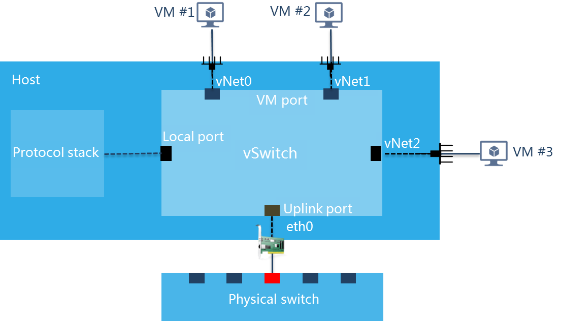
A virtual switch provides software-based switching between VMs, hosts, and the external network. A virtual switch provides the following ports:
VM port—A virtual NIC that connects to a VM.
Local port—A port that connects to the protocol stack on the host.
Uplink port—A physical NIC that connects to the host.
If a VLAN ID is configured on a virtual switch, you must assign the corresponding interface on the physical switch to the VLAN to ensure correct communication.
A virtual switch supports the following network types:
Management—Transmits control layer data between CVM and hosts.
Service—Transmits service data for VMs.
Storage—Transmits packets between hosts and IP SAN storage servers. This type of virtual switches cannot be used by VMs.
Backup—Transmits the backup data of VMs and backup data for disaster recovery. A host can have only one virtual switch or subnet of this type, and the virtual switch cannot be used by VMs. If you do not specify a backup network virtual switch, backup data is transmitted through the management network virtual switch.
Migration—Transmits the data for migrating VMs. A host can have only one virtual switch or subnet of this type, and the virtual switch cannot be used by VMs.
After you add a host to CVM, the system automatically creates a default virtual switch named vswitch0 for the management network on the host. If you do not configure any backup network or migration network, the backup and migration data for VMs will be transmitted through vswitch0.
Restrictions and guidelines
ARM hosts do not support NetFlow configuration.
Multiple virtual switches cannot belong to the same network.
You cannot delete a virtual switch when it is being used by VMs.
If only virtual switch vswitch0 exists in the system, do not delete the virtual switch. If you delete it, CVM cannot be accessed.
Editing a vSwitch might cause network connectivity issues and adversely impact services. Before you edit a vSwitch, verify the network settings for the vSwitch.
As a best practice to ensure storage service performance, do not use the backup network virtual switch as the storage network virtual switch, and vice versa.
After you modify a virtual switch with a backup network configured, you must reconfigure the network type of the virtual switch as backup if you want to use that network for disaster recovery.
Add a virtual switch
From the left navigation pane, select Resources > host pool name > host name or Resources > host pool name > cluster name > host name.
Click the vSwitches tab.
Click Add.
Configure the parameters as described in "Parameters."
Click Finish.
Modify a virtual switch
From the left navigation pane, select Resources > host pool name > host name or Resources > host pool name > cluster name > host name.
Click the vSwitches tab.
Click the
 icon for a virtual switch.
Configure the parameters as described in "Parameters."
Click Finish.
Start a virtual switch
From the left navigation pane, select Resources > host pool name > host name or Resources > host pool name > cluster name > host name.
Click the vSwitches tab.
Click the
 icon for a virtual switch.
In the dialog box that opens, click OK.
Delete a virtual switch
From the left navigation pane, select Resources > host pool name > host name or Resources > host pool name > cluster name > host name.
Click the vSwitches tab.
Click the
 icon for a virtual switch.
In the dialog box that opens, click OK.
Change the network type of a virtual switch from backup to disaster recovery
Restrictions and guidelines
ARM hosts do not support disaster recovery.
Procedure
From the left navigation pane, select Resources > host pool name > host name or Resources > host pool name > cluster name > host name.
Click the vSwitches tab.
Click the
 icon for a backup-network virtual switch or virtual switch vswitch0.
vswitch0 can be used as a backup-network virtual switch by default.
In the dialog box that opens, click OK.
Parameters
Network Type: Select network types for the virtual switch.
Mgmt—Network for transmitting control layer data between CVM and hosts.
Service—Network for transmitting service data of VMs.
Storage—Network for transmitting data between hosts and IP SAN storage servers or distributed storage. This type of virtual switches cannot be used by VMs.
Backup—Network for transmitting backup data between VMs and remote servers. A host can have only one virtual switch or subnet of this type and the virtual switch cannot be used by VMs.
Migration—Network for transmitting memory and disk image data for VM migration. A host can have only one virtual switch or subnet of this type and the virtual switch cannot be used by VMs.
Other—Network for transmitting data other than previously mentioned.
Forwarding Mode: Select the forwarding mode of the virtual switch.
VEB—Virtual Ethernet Bridge (VEB) mode. In this mode, the virtual switch forwards traffic based on software.
VXLAN (SDN)—Forwarding mode provided by the VXLAN solution based on SDN controllers and cloud computing management platforms.
VLAN ID: Specify a VLAN ID for the local port of the virtual switch. You can use VLAN to isolate host traffic from VM traffic at Layer 2.
Enable DPDK: Configure whether to enable DPDK or not. Enabling DPDK can improve the network performance of the VM.
MTU: Set the maximum packet length allowed by the virtual switch, in bytes. The MTU of virtual switch vswitch0 cannot be modified.
Enable Multicast: Enable multicast forwarding for the virtual switch. You cannot enable multicast for virtual switch vswitch0.
Physical Interface: Name of the interface on the physical NIC assigned to the virtual switch. A physical interface can be assigned to only one virtual switch. When all physical interfaces of the host are assigned to virtual switches, this parameter is not configurable. If the virtual switch is not assigned a physical interface, VMs attached to the virtual switch can communicate only with each other but cannot communicate with external networks. If you specify multiple physical interfaces for the virtual switch, you must configure the link aggregation mode and LB mode.
IPv4 Address: Enter an IPv4 address for the virtual switch.
Subnet Mask: Enter the subnet mask of the IPv4 address.
IPv4 Gateway: Enter an IPv4 gateway for the virtual switch. A host can have only one IPv4 gateway.
IPv6 Address: Enter an IPv6 address for the virtual switch.
Prefix Length: Enter the prefix length of the IPv6 address.
IPv6 Gateway: Enter an IPv6 gateway for the virtual switch. A host can have only one IPv6 gateway.
LAGG Mode: Set the link aggregation mode of the physical NICs. Options include Static and Dynamic. If dynamic link aggregation mode is used, you must enable LACP on the physical switch. This mode is configurable only when multiple physical interfaces exist.
LB Mode: Set the load balancing mode of physical NICs. This parameter is configurable only when multiple physical interfaces exist.
Advanced—Performs load balancing for packets based on the Ethernet type, IP protocol, source IP address, destination IP address, source port number, and destination port number.
Basic—Performs load balancing for packets based on the source MAC address and VLAN tag.
Active/Standby—Performs load balancing for packets based on the primary and backup roles of physical NICs. If the primary NIC fails, traffic is automatically switched to the backup NIC.
Fallback: Select whether to switch services from the backup NIC back to the primary NIC after the primary NIC recovers from a fault. This parameter is required when the load balancing mode is Active/Standby.
Primary NIC Selection: Select the method used to select the primary NIC. This parameter is required when the load balancing mode is Active/Standby.
Rate-Based—The system automatically selects the primary NIC based on the rates of the NICs. The NIC with the highest rate becomes the primary NIC. When multiple NICs have the same rate, the system randomly selects a NIC as the primary NIC.
Manual—Specify the primary NIC by arranging the LB priorities of the NICs. The NIC with the highest priority is the primary NIC. You must configure the LB priorities for the NICs in this mode.