- Table of Contents
- Related Documents
-
| Title | Size | Download |
|---|---|---|
| 01-FC and FCoE configuration | 1.64 MB |
FC and FCoE configuration preparation and guidelines
Licensing requirements for FC and FCoE
FC and FCoE features supported in different FCoE modes
Configuring the system operating mode
FC interface tasks at a glance
Changing the port type between a Layer 2 Ethernet interface and an FC interface
Restrictions and guidelines for port type changing
Changing a Layer 2 Ethernet interface to an FC interface
Changing an FC interface back to a Layer 2 Ethernet interface
Restoring the default settings for an FC interface
Display and maintenance commands for FC interfaces
Restrictions and guidelines: VFC interface configuration
Restoring the default settings for a VFC interface
Display and maintenance commands for VFC interfaces
Configuring FC link aggregation
FC link aggregation networking guidelines
FC link aggregation tasks at a glance
Configuring an FC aggregate interface
Assigning an FC interface to an FC aggregation group
Enabling local-first load sharing
Restoring the default settings for an FC aggregate interface
Display and maintenance commands for FC link aggregation
FC link aggregation configuration examples
Example: Configuring FC link aggregation
Restrictions and guidelines for basic FC and FCoE configuration
Basic FC and FCoE tasks at a glance
Enabling FC and FCoE for a VLAN and mapping the VLAN to a VSAN
Setting the FC-MAP value of the FCoE network
About setting the FC-MAP value
Setting the FKA advertisement interval value of the FCoE network
About the FKA advertisement interval
Setting the FKA advertisement interval value
Setting the FCF priority of the FCoE network
Setting the system FCF priority
Setting the VFC interface FCF priority
Display and maintenance commands for basic FCoE
Basic FC and FCoE configuration examples
Example: Configuring basic FC and FCoE by using FC interfaces and VFC interfaces
Example: Configuring basic FCoE by using VFC interfaces
Restrictions and guidelines: VSAN configuration
Restrictions and guidelines for configuring an access VSAN
Assigning an interface to a VSAN as an access port
Assigning interfaces to a VSAN as access ports in bulk
Display and maintenance commands for VSANs
Example: Configuring VSANs by using FC interfaces
Example: Configuring VSANs by using VFC interfaces
Restrictions and guidelines: Building a fabric
Fabric building tasks at a glance
Enabling or disabling the fabric configuration feature
Restrictions and guidelines for enabling or disabling the fabric configuration feature
Enabling the fabric configuration feature
Disabling the fabric configuration feature
Configuring an allowed domain ID list
Configuring the persistent FC address feature
Setting the maximum number of logged-in nodes
Setting fabric timers in system view
Setting fabric timers in VSAN view
Configuring the fabric reconfiguration feature
Enabling the automatic reconfiguration feature
Manually initiating a fabric reconfiguration
Configuring an interface to reject incoming RCF requests
Enabling SNMP notifications for the fabric or name service module
Configuring and obtaining FC4 information of nodes
Enabling SCSI-FCP information autodiscovery
Configuring the default FC4 information for a node
Display and maintenance commands for a fabric
Fabric building configuration examples
Example: Building a fabric statically
Example: Building a fabric dynamically
Configuring FC routing and forwarding
About FC routing and forwarding
Setting the shortest SPF calculation interval for a VSAN
Setting the minimum LSR arrival interval for a VSAN
Setting the minimum LSR refresh interval for a VSAN
Setting the FSPF cost for an interface
Setting the hello interval for an interface
Setting the dead interval for an interface
Setting the LSR retransmission interval for an interface
Disabling FSPF for an interface
Display and maintenance commands for FC routing and forwarding
FC routing configuration examples
Example: Configuring static FC routing by using FC interfaces
Example: Configuring static FC routing by using VFC interfaces
Example: Configuring FSPF by using FC interfaces
Example: Configuring FSPF by using VFC interfaces
Zone distribution in basic zoning mode
Zone distribution in enhanced zoning mode
Zone merge in basic zoning mode
Zone merge in enhanced zoning mode
Restrictions and guidelines: FC zone configuration
Configuring the default zone policy
Configuring the zone distribution and merge type
Configuring the merge control mode
Activating a zone set and distributing it to the entire fabric
Triggering a complete distribution
Renaming a zone alias, zone, or zone set
Copying a zone alias, zone, or zone set
Enabling SNMP notifications for the zone module
Display and maintenance commands for FC zones
FC zones configuration examples
FIP snooping tasks at a glance
Configuring the operating mode of an Ethernet interface
Setting the FC-MAP value for a VLAN
Display and maintenance commands for FIP snooping
FIP snooping configuration examples
Example: Configuring FIP snooping
Port security tasks at a glance
Manually configuring binding entries
Enabling auto learning or Smart SAN auto learning
Converting learned entries to static entries
Enabling SNMP notifications for port security
Display and maintenance commands for port security
Port security configuration examples
Example: Configuring port security by using FC interfaces
Example: Configuring port security by using VFC interfaces
Display and maintenance commands for FCS
Display and maintenance commands for FDMI
FC ping configuration examples
Example: Configuring FC ping by using FC interfaces
Example: Configuring FC ping by using VFC interfaces
FC tracert configuration examples
Example: Configuring FC tracert by using FC interfaces
Example: Configuring FC tracert by using VFC interfaces
Comprehensive FC and FCoE configuration examples
Example: Configuring FCoE by using VFC interfaces
Example: Configuring FC and FCoE by using FC interfaces and VFC interfaces (in standalone mode)
Appendix A Fabric address assignment
Appendix B Well-known fabric addresses
FC and FCoE overview
Fibre Channel (FC) is a data transmission protocol used in a storage area network (SAN). Fibre Channel over Ethernet (FCoE) transports FC over Ethernet.
FC SAN
An FC SAN provides an external storage environment for servers by using the FC protocol suite. FC SANs can meet the reliable storage, access, and backup requirements for large-capacity data.
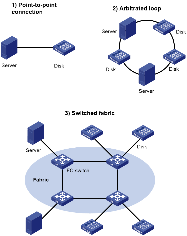
Figure 1 shows three FC SAN networking methods. The first two networking methods are simple and can connect only a limited number of devices.
· Point-to-point connection—Directly connects a server and a disk device.
· Arbitrated loop—Supports up to 126 devices.
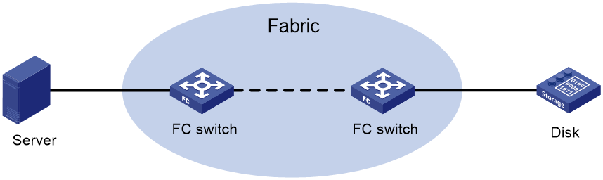
An FC SAN refers to a network that includes FC switches and nodes. A fabric refers to a transmission network that includes FC switches.
FC protocol
The servers, FC switches, and disk devices in an FC SAN must all support FC.
WWN
The world wide name (WWN) is a 64-bit address. It identifies a fabric or an entity (such as an FC switch, node, or port) in an FC SAN. The upper-layer protocol of FC uses WWNs for communication. Each entity has a factory-assigned, globally unique WWN.
FC address
The FC protocol accesses communication entities in an FC SAN through FC addresses. An FC address is also known as an FC ID.
Figure 2 shows the structure of an FC address. The FC address is 24 bits long and contains the following 8-bit fields:
· Domain_ID—A domain represents a switch and all N_Ports connected to the switch. For more information about N_Ports, see "Port modes." A domain ID, which is in the range of 1 to 239, uniquely identifies an FC switch. Different FC switches in the same fabric have different domain IDs.
· Area_ID—One or more N_Ports on the same node can be assigned to an area, which is identified by an area ID.
· Port_ID—The Port_ID field identifies an N_Port.
Figure 2 Structure of an FC address
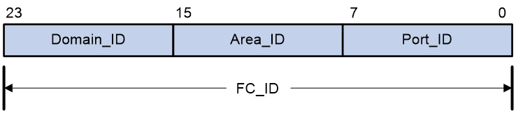
An FC address can uniquely identify an N_Port on a node. Different N_Ports on the same node have different FC addresses. FC switches use domain IDs to route messages between each other.
The FC protocol standardizes the FC address usage. For more information, see "Appendixes."
Port modes
In a switched fabric, nodes and FC switches communicate through interfaces operating in different modes.
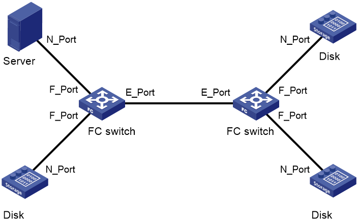
A node supports the following port modes:
· N_Port—Directly connects to a fabric.
· NL_Port—Connects to a fabric through an arbitrated loop.
An FC switch provides the following port modes:
· E_Port—Connects to an E_Port on another FC switch.
· F_Port—Connects to an N_Port on a node or an NP_Port on another FC switch.
· NP_Port—Connects to an F_Port on another FC switch.
· G_Port—Operates in auto mode to negotiate the operating mode with its peer.
¡ If the peer is an E_Port, the G_Port acts as an E_Port.
¡ If the peer is an N_Port or NP_Port, the G_Port acts as an F_Port.
¡ If both ends are G_Ports, they both act as E_Ports.
¡ If the peer is an F_Port, the negotiation fails.
E_Ports connect FC switches to form a fabric, and F_Ports connect the nodes to FC switches in the fabric.
Communication flow
FC switches provide data transmission services. Through FC switches, a server sends instructions and data to disk devices and reads data from disk devices.
Figure 4 FC SAN communication model
The following takes a server accessing a disk device as an example to see how data communication occurs in an FC SAN.
1. The server and the disk device send fabric login (FLOGI) packets to register with the FC switches. Then, the FC switches assign FC addresses to each directly-connected node.
A FLOGI packet contains information that includes the port WWN, node WWN, and the expected FC address.
2. The registered server and disk device send name service registration requests to their respective access FC switches to register name service information, including FC4 information. Finally, each FC switch in the fabric stores the name service information of all nodes. For more information about FC4 information, see "Configuring and obtaining FC4 information of nodes."
3. To access a disk device, the server must obtain the list of disk devices in the fabric and their WWNs and FC addresses. For this purpose, the server must send a name service query request to its directly-connected FC switch.
4. After the server obtains the FC address of the disk device, the server can send FC frames destined to the FC address to the FC switch nearby.
5. When the FC switch receives the FC frame from the server, it performs the following operations:
¡ Queries its FIB table for a data forwarding path according to the destination FC address.
¡ Forwards the FC frame to the next-hop FC switch.
6. The next-hop FC switch forwards the FC frame in the same way, until the FC switch at the last hop forwards the FC frame to the destination disk device.
|
|
NOTE: A FIB table is generated by the FC switch through calculation based on the FC routing protocol or configured static routes. |
VSAN
In actual applications, the data is insecure if the data of all users is transmitted in the same FC SAN. You can divide one physical FC SAN into multiple virtual storage area networks (VSANs). VSANs are separated from one another and provide independent services. This enhances adaptability and security of the network and offers more effective services for users. For more information about VSANs, see "Configuring VSANs."
FC zone
The VSAN feature divides one physical SAN into multiple logical SANs. A VSAN, however, cannot perform access control over the servers and disk devices (or the N_Ports) connected to a fabric. N_Ports in the same VSAN can access one another only if these N_Ports register name services. This creates data security risks.
Zoning can solve the preceding problem by dividing a VSAN into zones and adding N_Ports to different zones for different purposes. N_Ports in different zones are separated to implement access control.
For more information about FC zones, see "Configuring FC zones."
FCoE
About FCoE
A data center using the FC SAN technique typically includes separate local area networks (LANs) and SANs. LANs carry traditional Ethernet/IP services, and SANs carry network storage services.
To provide services for LANs and use SANs for storage simultaneously in a traditional network, the servers must use independent Ethernet adapters and FC adapters. In addition, the IP switches and the FC switches are also independent and have independent network connections. Such a network needs many switches, network adapters, and cables, and it brings high investments and maintenance costs and low scalability.
FCoE was introduced to solve this problem. FCoE transports FC over Ethernet. In an FCoE solution:
· The server uses an FCoE-capable Ethernet adapter.
· The FCoE switch (FCoE forwarder) integrates the functions of both the traditional IP switch and FC switch.
FCoE reduces the number of network adapters, switches, and cables, and the network operation and maintenance workload. In all, FCoE reduces the total cost.
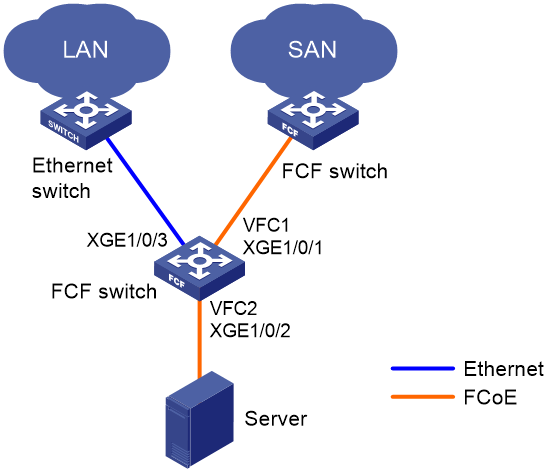
Figure 5 FCoE for I/O consolidation
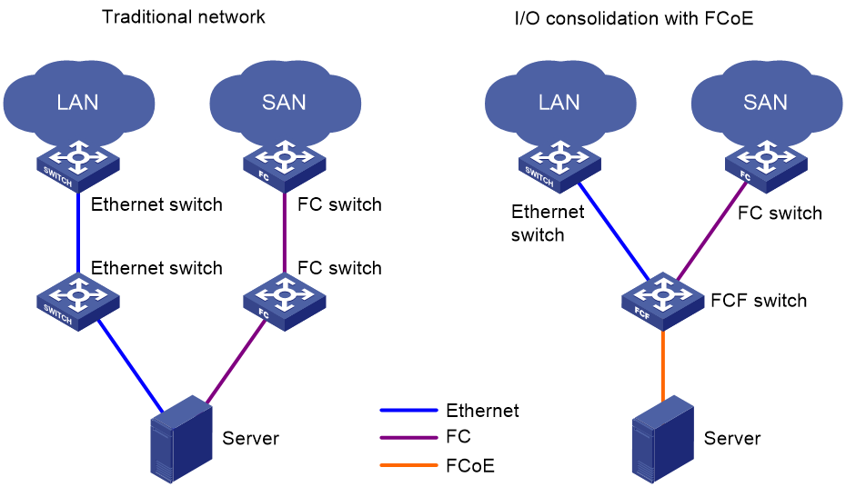
As shown in Figure 5:
· In the traditional network, the server is connected to the LAN through an Ethernet interface and to the SAN through an FC interface.
· In the FCoE network, the server is connected to the FCoE-capable FCF switch. Then, the FCF switch is connected to the LAN through an Ethernet interface and to the SAN through an FC interface. The link between the server and the FCF switch can transmit both Ethernet packets and FC frames.
Basic concepts
As shown in Figure 6, the link between the FCF switch and the ENode can receive and send both Ethernet frames and FC frames. ENodes can transport FC over Ethernet. ENodes include servers and disk devices.

VFC interface and VN interface
A virtual fibre channel (VFC) interface is a logical interface manually created on an FCF switch to simulate the functionality of a physical FC interface.
To use a VFC interface, bind it to a physical Ethernet interface.
You can connect either an ENode or an FCF switch to a VFC interface.
VFC interfaces support E mode and F mode (default).
The virtual node (VN) interface is a logical interface on an ENode to simulate the function of a physical FC interface.
FIP protocol
FCoE initialization protocol (FIP) is an FCoE control protocol that establishes and maintains virtual links.
FIP establishes a virtual link between the VFC interface of an FCF switch and either of the following:
· A VN interface of an ENode.
· A VFC interface of another FCF switch.
The virtual links provide a physical infrastructure for transmitting FC frames over Ethernet.
FCoE frames
To transmit an FC frame over Ethernet, FCoE encapsulates the FC frame in an FCoE frame by adding an Ethernet frame header to the FC frame.
An FCoE frame uses Ethernet II encapsulation, which has the following fields in the Ethernet header:
· EtherType 0x8906.
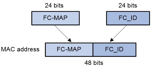
· Destination MAC address/source MAC address—The definitions of this field are different for switches and nodes.
¡ For a switch, this field is the FCoE MAC address of the switch (which can be displayed by using the display fcoe command).
¡ For a node, this field is the fabric provided MAC address (FPMA) of the node. As shown in Figure 7, an FPMA contains the following elements:
- The FC-MAP as the 24 most significant bits.
- The FC address of the VN interface as the 24 least significant bits.
The FC-MAP takes the value of the switch FC-MAP, 0x0efc00 by default and configurable by using the fcoe fcmap command.
How FCoE works
Figure 8 Block diagrams of the ENode and the FCF switch

Procedure for receiving and sending FC frames over Ethernet
An FC frame is transmitted over Ethernet using the following workflow:
1. FIP establishes a virtual link between the VFC interface of the FCF switch and one of the following interfaces:
¡ A VN interface of an ENode.
¡ A VFC interface of another FCF switch.
2. After the virtual link is established, the FCF switch encapsulates the FC frame in an FCoE frame and sends it out.
3. After receiving the FCoE frame, the FCF switch removes its Ethernet header to send the original FC frame to the upper layer for processing.
How FIP works
FIP establishes and maintains virtual links between a VFC interface and a VN interface or between VFC interfaces.
FIP uses Discovery Solicitation packets and Discovery Advertisement packets. Discovery Advertisement packets include the following types:
· Solicited Discovery Advertisement—A reply for a Discovery Solicitation.
· Unsolicited Discovery Advertisement—Periodically sent to advertise the presence of a virtual link or maintain an existing virtual link.
The following example shows how a virtual link is established between an FCF switch and an ENode.

As shown in Figure 9, the following workflow is used to establish a virtual link:
1. The ENode sends a Discovery Solicitation containing its FCoE MAC address.
2. After receiving the Discovery Solicitation, the FCF switch acts differently depending on whether the receiving VFC interface is bound to an FCoE MAC address.
¡ If it is not bound to an FCoE MAC address, the switch learns the FCoE MAC address and replies with a solicited Discovery Advertisement. The fcf priority field of the solicited Discovery Advertisement transports the FCF priority of the VFC interface.
¡ If it is bound to an FCoE MAC address, the switch identifies whether the FCoE MAC address in the Discovery Solicitation matches the bound FCoE MAC address.
- If they match, the switch replies with a solicited Discovery Advertisement, whose fcf priority field carries the FCF priority of the VFC interface.
- If they do not match, the switch discards the Discovery Solicitation.
3. The FCF switch periodically sends unsolicited Discovery Advertisements, whose fcf priority field carries the FCF priority of the system.
The sending interval is specified by using the fcoe fka-adv-period command and defaults to 8 seconds.
4. After receiving the Discovery Advertisements, the ENode determines the FCF switch with the highest priority according to the fcf priority field. Then, the ENode sends a FLOGI request to that switch for login.
5. After receiving the FLOGI request, the FCF switch identifies whether the source MAC address matches its learned or bound FCoE MAC address.
¡ If they match, the FCF switch sends a FLOGI LS_ACC, which indicates that the establishment of the virtual link is completed.
¡ If they do not match, the FCF switch discards the FLOGI request.
6. The FCF switch also periodically sends unsolicited Discovery Advertisements to maintain established virtual links. If the ENode fails to receive an unsolicited Discovery Advertisement within a period 2.5 times the FKA advertisement interval, it deletes the virtual link.
FCoE modes
An FC and FCoE-capable switch can operate in non-FCoE mode or in an FCoE mode.
The following FCoE modes are available:
· FCF mode.
· Transit mode.
FCF mode
When the switch operates in this mode, it is an FCF switch and supports E_Ports and F_Ports. An FCF switch can connect to the following elements:
· An E_Port on another FCF switch through its E_Port.
· An N_Port or NP_Port through its F_Port.
An FCF switch encapsulates FC frames in Ethernet frames and uses FCoE virtual links to simulate physical FC links. An FCF switch provides the FC switch features on a lossless Ethernet network.
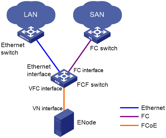
In an FCoE environment as shown in Figure 10, an FCF switch can perform the following operations:
· Connect to an Ethernet switch through an Ethernet interface.
· Connect to an FC switch through an FC interface.
· Connect to an ENode or FCF switch through a VFC interface. In this case, an FCoE virtual link is established between the Ethernet interfaces of the two devices. The FCoE virtual link provides communication over a lossless Ethernet network. The peer end of the FCoE virtual link can be a VN interface or a VFC interface.
Like an FC switch, each FCF switch is assigned a domain ID. Each FC SAN supports a maximum number of 239 domain IDs, so an FC SAN cannot have more than 239 switches.
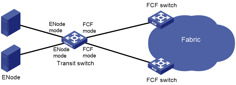
Transit mode
When the switch operates in this mode, it is a Transit switch. You can configure Ethernet interfaces on a Transit switch to operate in ENode mode or FCF mode:
· An Ethernet interface connected to an ENode must be configured to operate in ENode mode.
· An Ethernet interface connected to an FCF switch must be configured to operate in FCF mode.
The ENode mode allows an Ethernet interface to receive traffic only from an ENode. The FCF mode allows an Ethernet interface to receive traffic only from an FCF switch.
FCoE supports FC SANs built on lossless Ethernet networks, and allows Transit switches to be added between FCF switches and ENodes. Figure 11 shows a scenario where ENodes are connected to FCF switches through a Transit switch.
Figure 11 Transit network diagram
When Transit switches are interconnected, you must configure Ethernet interfaces to operate in the correct modes. As shown in Figure 12, ENode 2 can register with only FCF switch 2. To register ENode 2 with FCF switch 1, you must swap the operating modes of the Ethernet interfaces that connect the two Transit switches.
Figure 12 Transit cascading network diagram
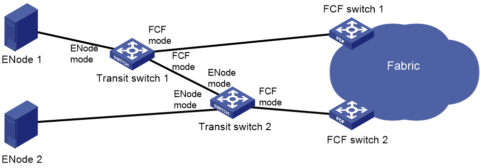
Figure 13 shows a network scenario where both Transit and NPV switches are present.
Figure 13 Network diagram for NPV and Transit switches
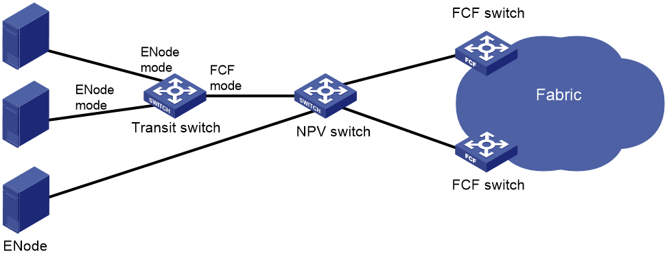
The primary responsibilities of Transit switches are filtering and forwarding FCoE protocol packets. They can recognize and control FCoE packets as compared to standard Ethernet switches. However, they do not provide FCoE traffic processing capabilities as complex as FCF switches or NPV switches.
Protocols and standards
· FC-FS-3, Fibre Channel - Framing and Signaling - 3
· FC-SW-5, Fibre Channel - Switch Fabric - 5
· FC-LS-2, Fibre Channel - Link Services - 2
· FC-GS-6, Fibre Channel - Generic Services - 6
· FC-BB-5, Fibre Channel - Back Bone – 5
FC and FCoE configuration preparation and guidelines
Licensing requirements for FC and FCoE
FC and FCoE require a license to run on the device. For more information about licenses, see Fundamentals Configuration Guide.
FC and FCoE features supported in different FCoE modes
Switches operating in different FCoE modes support different FC and FCoE features, as shown in Table 1.
Table 1 FC and FCoE features supported in different FCoE modes
|
FC and FCoE feature |
FCF switch |
NPV switch FCF-NPV switch (NPV mode) |
Transit switch |
|
Supported. |
Supported. |
Not supported. |
|
|
Supported. |
Supported. |
Not supported. |
|
|
Supported. |
Supported. |
Not supported. |
|
|
Supported. |
Supported. |
Not supported. |
|
|
Supported. |
Supported. |
Not supported. |
|
|
Supported. |
Only the Setting fabric timers feature is supported. |
Not supported. |
|
|
Supported. |
Only the following features are supported: · Displaying FC routing table information. · Displaying FC FIB table information. · Display FC Exchange table information. |
Not supported. |
|
|
Supported. |
Not supported. |
Not supported. |
|
|
Not supported. |
Not supported. |
Supported. |
|
|
Supported. |
Not supported. |
Not supported. |
|
|
Supported. |
Not supported. |
Not supported. |
|
|
Supported. |
Not supported. |
Not supported. |
|
|
Supported. |
Not supported. |
Not supported. |
|
|
Supported. |
Not supported. |
Not supported. |
Prerequisites for FC and FCoE
Configuring the system operating mode
About this task
The switch supports FC and FCoE only when it is operating in advanced mode. For more information about configuring system operating modes, see device management in Fundamentals Configuration Guide.
Procedure
1. Enter system view.
system-view
2. Configure the system operating mode.
For information about configuring the system operating mode, see device management in Fundamentals Configuration Guide.
3. Save the running configuration.
For information about saving the running configuration, see file system management in Fundamentals Configuration Guide.
4. Reboot the switch.
For information about rebooting the switch, see device management in Fundamentals Configuration Guide.
Configuring an FCoE mode
Restrictions and guidelines
A switch can operate in non-FCoE mode or in one of the following FCoE modes: FCF, NPV, FCF-NPV, and Transit.
To configure a switch operating in one FCoE mode to operate in another FCoE mode, perform the following tasks:
1. Configure the switch to operate in the non-FCoE mode.
2. Configure the switch to operate in the target FCoE mode.
Converting the switch to non-FCoE mode also clears all FC- and FCoE-related settings in the original FCoE mode except FC, FC aggregate, and VFC interfaces.
Procedure
1. Enter system view.
system-view
2. Configure an FCoE mode for the switch.
fcoe-mode { fcf | transit }
By default, a switch operates in non-FCoE mode.
3. Display the FCoE mode of the switch.
display fcoe-mode
This command is available in any view.
Configuring FC interfaces
About FC interfaces
An FC interface is a physical interface. It connects to a node (server or disk) or FC switch for transmitting and receiving FC frames. An FC interface can be connected to only an FC interface.
FC interface tasks at a glance
To configure FC interfaces, perform the following tasks:
1. (Optional.) Changing the port type between a Layer 2 Ethernet interface and an FC interface
2. Configuring an FC interface
3. (Optional.) Restoring the default settings for an FC interface
Changing the port type between a Layer 2 Ethernet interface and an FC interface
Restrictions and guidelines for port type changing
Only the 10-GE Layer 2 Ethernet interfaces on an LSWM124XG2QFC expansion interface card installed in an LSXM1TGS24QGMODHB1 card can be separately changed to FC interfaces. When you execute the port-type command on a Layer 2 Ethernet interface, other interfaces are not affected. To change a Layer 2 Ethernet interface to an FC interface, use the port-type fc command in Layer 2 Ethernet interface view. To change an FC interface back to a Layer 2 Ethernet interface, use the port-type ethernet command in FC interface view.
Changing a Layer 2 Ethernet interface to an FC interface
1. Enter system view.
system-view
2. Enter Layer 2 Ethernet interface view.
interface interface-type interface-number
3. Change the interface to an FC interface.
port-type fc
By default, interfaces on H3C LSWM124XG2QFC expansion interface modules are Layer 2 Ethernet interfaces.
|
|
CAUTION: After you change the port type, all settings of the interface are restored to the default settings of the new port type. |
This command deletes the original Layer 2 Ethernet interface, creates an FC interface, and leads you to the FC interface view.
Changing an FC interface back to a Layer 2 Ethernet interface
1. Enter system view.
system-view
2. Enter FC interface view.
interface fc interface-number
3. Change the FC interface back to a Layer 2 Ethernet interface.
port-type ethernet
By default, interfaces on H3C LSWM124XG2QFC expansion interface modules are Layer 2 Ethernet interfaces.
|
|
CAUTION: After you change the port type, all settings of the interface are restored to the default settings of the new port type. |
This command deletes the original FC interface, creates a Layer 2 Ethernet interface, and leads you to the Layer 2 Ethernet interface view.
Configuring an FC interface
1. Enter system view.
system-view
2. Enter FC interface view.
interface fc interface-number
3. Configure the mode of the FC interface.
fc mode { auto | e | f }
FC interfaces on an FCF switch support only auto, E, and F modes. The default is auto mode.
4. (Optional.) Set the interface rate.
speed { 2000 | 4000 | 8000 | auto }
By default, the interface rate is autonegotiated.
5. (Optional.) Configure a description for the FC interface.
description text
By default, the description of an FC interface is in the format interface name Interface, for example, Fc1/0/1 Interface.
6. (Optional.) Set the buffer-to-buffer Credit (BB_Credit) value for the FC interface.
fcb2bcredit credit-value
The default setting is 15.
7. (Optional.) Configure the fill word mode for the FC interface.
fill-word { idle-arbff | idle-idle }
By default, an 8-Gbps FC interface uses the idle-arbff mode.
This command is available only for 8-Gbps FC interfaces. 2-Gbps and 4-Gbps FC interfaces support only the idle-idle mode.
The configuration takes effect only after you execute the shutdown command and then the undo shutdown command.
8. (Optional.) Set the expected bandwidth of the interface.
bandwidth bandwidth-value
By default, the expected bandwidth (in kbps) is the interface baud rate divided by 1000.
The expected bandwidth of an interface affects the link costs in FSPF. You can control the route selection by setting the expected bandwidth.
9. Bring up the FC interface.
undo shutdown
By default, an FC interface is up.
Restoring the default settings for an FC interface
Restrictions and guidelines
The default command might interrupt ongoing network services. Make sure you are fully aware of the impact of this command when you execute it on a live network.
This command might fail to restore the default settings for some commands for reasons such as command dependencies or system restrictions. Use the display this command in interface view to identify these commands. Then use their undo forms or follow the command reference to restore their default settings. If your restoration attempt still fails, follow the error message instructions to resolve the problem.
Procedure
1. Enter system view.
system-view
2. Enter FC interface view.
interface fc interface-number
3. Restore the default settings for the interface.
default
Display and maintenance commands for FC interfaces
Execute display commands in any view and reset commands in user view.
|
Task |
Command |
|
Display FC interface information. |
display interface [ fc [ interface-number ] ] [ brief [ description | down ] ] |
|
Clear statistics for FC interfaces. |
reset counters interface [ fc [ interface-number ] ] |
Configuring VFC interfaces
About VFC interfaces
A VFC interface can connect to an ENode or a switch. A VFC interface is a virtual logical interface. It implements the functionality of an FC interface. To make a VFC interface work, bind it to a physical Ethernet interface. The switch encapsulates the FC packets on a VFC interface in FCoE packets and transmits the packets over the Ethernet interface bound to the VFC interface.
Restrictions and guidelines: VFC interface configuration
If the Ethernet interface bound to a VFC interface is a hybrid or trunk port, for the VFC interface to come up, make sure the Ethernet interface allows its PVID. If its PVID is VLAN 1, the undo port hybrid vlan 1 or undo port trunk permit vlan 1 command cannot be configured on the Ethernet interface. If its PVID is not VLAN 1, the port hybrid vlan pvid untagged or port trunk permit vlan pvid command must be configured on the Ethernet interface.
To avoid FCoE packet loss in the Ethernet, you must perform the following tasks on the Ethernet interface bound to the VFC interface:
· Configure DCBX, PFC in auto mode, and ETS on the Ethernet interfaces that connect the switch to servers.
· Configure DCBX and PFC in auto mode on the Ethernet interfaces that connect the switch to disk devices.
· Forcibly enable PFC on the Ethernet interfaces connected to other switches.
For more information about DCBX, PFC, and ETS, see LLDP configuration in Layer 2—LAN Switching Configuration Guide.
Configuring a VFC interface
1. Enter system view.
system-view
2. Create a VFC interface and enter its view.
interface vfc interface-number
3. Configure the mode of the VFC interface.
fc mode { e | f }
By default, the mode of a VFC interface is F.
VFC interfaces on an FCF switch support only E and F modes.
4. Bind the VFC interface to an Ethernet interface.
bind interface interface-type interface-number [ mac mac-address ]
By default, no Ethernet interface is bound to a VFC interface.
The VFC interface sends and receives packets through the Ethernet interface bound to it.
5. (Optional.) Configure a description for the VFC interface.
description text
By default, the description of an interface is interface name Interface, for example, Vfc1 Interface.
6. (Optional.) Set the expected bandwidth of the interface.
bandwidth bandwidth-value
By default, the expected bandwidth (in kbps) is the interface baud rate divided by 1000.
The expected bandwidth of an interface affects the link costs in FSPF. You can control the route selection by setting the expected bandwidth.
7. Bring up the VFC interface.
undo shutdown
By default, a VFC interface is up.
Restoring the default settings for a VFC interface
Restrictions and guidelines
The default command might interrupt ongoing network services. Make sure you are fully aware of the impact of this command when you execute it on a live network.
This command might fail to restore the default settings for some commands for reasons such as command dependencies or system restrictions. Use the display this command in interface view to identify these commands. Then use their undo forms or follow the command reference to restore their default settings. If your restoration attempt still fails, follow the error message instructions to resolve the problem.
Procedure
1. Enter system view.
system-view
2. Enter VFC interface view.
interface vfc interface-number
3. Restore the default settings for the interface.
default
Display and maintenance commands for VFC interfaces
Execute display commands in any view and reset commands in user view.
|
Task |
Command |
|
Display VFC interface information. |
display interface [ vfc [ interface-number ] ] [ brief [ description | down ] ] |
|
Clear statistics for VFC interfaces. |
reset counters interface [ vfc [ interface-number ] ] |
Configuring FC link aggregation
About FC link aggregation
FC link aggregation aggregates multiple physical FC interfaces into a logical FC aggregation group.
FC link aggregation delivers the following benefits:
· Increased bandwidth—The bandwidth of the FC aggregate interface is the total bandwidth of all available member interfaces.
· Load sharing—Incoming/outgoing traffic is distributed across multiple member interfaces of the FC aggregation group.
· Improved connection reliability—When a member interface goes down, the traffic on it automatically switches over to other available member interfaces. This avoids service interruption and improves the connection reliability of the whole FC aggregate link.
Basic concepts
FC aggregation group, member interface, and FC aggregate interface
FC link aggregation aggregates multiple physical FC interfaces into a logical FC aggregation group. An FC aggregation group is a group of FC interfaces, which are called member interfaces of the FC aggregation group. For each FC aggregation group, a logical interface called an FC aggregate interface is created. When you create an FC aggregate interface, the device automatically creates an FC aggregation group with the same number as the FC aggregate interface.
Member interface status
A member interface in an FC aggregation group can be in either of the following states:
· Selected—A Selected member interface can forward traffic.
· Unselected—An Unselected member interface cannot forward traffic.
How FC link aggregation works
FC aggregate interface operating mode
The operating mode of an FC aggregate interface is determined as follows:
· When the configured mode is E or F, the operating mode is the configured mode.
· When the configured mode is auto, the operating mode is the same as the first member interface that goes up at the link layer. Possible operating modes are E and F.
When the configured mode of an FC aggregate interface is changed, all member interfaces will perform negotiation again.
Choosing Selected member interfaces
Any of the following conditions might trigger a process of choosing Selected member interfaces from member interfaces:
· A new member interface joins in the FC aggregation group.
· A member interface leaves the FC aggregation group.
· The state (up or down) of a member interface changes.
The states of FC aggregation group member interfaces are determined as follows:
· When the configured mode of an FC aggregate interface is E or F, the configured mode of the member interfaces is the same as the FC aggregate interface. The member interfaces perform link negotiation based on the configured mode. All member interfaces that pass the negotiation and have the highest speed become Selected.
· When the configured mode of an FC aggregate interface is auto, the configured mode of the member interfaces is also auto. The member interfaces perform link negotiation based on the auto mode. The operating mode negotiation result might be E or F mode. The operating mode of the FC aggregate interface is the operating mode of the first member interface that goes up at the link layer. All interfaces operating in the same mode as the FC aggregate interface and with the highest speed are Selected.
When an FC aggregation group has Selected member interfaces, the FC aggregate interface physically goes up and negotiates VSAN parameters.
Speed of an FC aggregate interface
The speed of an FC aggregate interface is the sum of the speed of each Selected member interface in the FC aggregation group.
Load sharing mode
An FC aggregate interface forwards traffic through its Selected member interfaces. When multiple Selected member interfaces exist in an FC aggregation group, the device chooses Selected member interfaces for forwarding traffic according to its load balancing mode. The following load balancing modes are available:
· Source FC_ID and destination FC_ID—Packets with the same source FC_ID and destination FC_ID are classified into one flow. Packets of the same flow are forwarded on the same Selected member interface.
· Exchange—Packets with the same exchange are classified into one flow. An exchange is uniquely identified by the combination of source FC_ID, destination FC_ID, and initiator Exchange_ID. Packets of the same flow are forwarded on the same Selected member interface.
FC link aggregation networking guidelines
To make FC link aggregation operate correctly, follow these restrictions and guidelines when you build an FC link aggregation network:
· The FC links between switches and nodes cannot be aggregated.
· FC links between two switches can be aggregated. The two switches can operate in the same FCoE mode or in different FCoE modes.
· Two FC link aggregation-enabled switches must communicate through FC aggregate interfaces. The member interfaces of a local FC aggregation group must be connected to member interfaces of one FC aggregation group on the peer end.
Figure 14 shows a correct FC link aggregation network.
Figure 14 Correct FC link aggregation networks

Figure 15 shows an incorrect FC link aggregation network. The errors include:
· The member interfaces of a local FC aggregation group are not connected to member interfaces of one FC aggregation group on the peer end.
· An FC aggregate interface is on one end of the link, and an FC interface is on the other end of the link.
To modify the network errors, perform the following tasks:
1. Use the shutdown command to shut down the FC aggregate interfaces.
2. Correctly configure the FC aggregation groups and member interfaces.
3. Use the undo shutdown command to bring up the FC aggregate interfaces.
Figure 15 Incorrect FC link aggregation networks

FC link aggregation tasks at a glance
To configure FC link aggregation, perform the following tasks:
1. Configuring an FC aggregate interface
2. Assigning an FC interface to an FC aggregation group
3. (Optional.) Enabling local-first load sharing
4. (Optional.) Restoring the default settings for an FC aggregate interface
Configuring an FC aggregate interface
1. Enter system view.
system-view
2. Create an FC aggregate interface and enter its view.
interface san-aggregation interface-number
After you create an FC aggregate interface, the system automatically creates an FC aggregation group numbered the same.
3. Configure the mode of the FC aggregate interface.
fc mode { auto | e | f }
FC aggregate interfaces on an FCF switch support only auto, E, and F modes. The default is auto mode.
4. (Optional.) Configure a description for the FC aggregate interface.
description text
By default, the description of an FC aggregate interface is interface name Interface, for example, SAN-Aggregation3 Interface.
5. (Optional.) Set the expected bandwidth for the FC aggregate interface.
bandwidth bandwidth-value
By default, the expected bandwidth (in kbps) is the interface baud rate divided by 1000.
The baud rate of an FC aggregate interface is the speed of the FC aggregate interface, which is the sum of the speed of each Selected FC interface.
The expected bandwidth of an interface affects the link costs in FSPF. You can control the route selection by setting the expected bandwidth.
6. Bring up the FC aggregate interface.
undo shutdown
By default, an FC aggregate interface is up.
Assigning an FC interface to an FC aggregation group
Restrictions and guidelines
An FC interface can be assigned to only one FC aggregation group.
Before you assign an FC interface to an FC aggregation group, use the shutdown command to shut down the FC interface. After assigning the FC interface to the FC aggregation group, perform the following tasks:
1. Assign the peer FC interface to the peer FC aggregation group.
2. Use the undo shutdown command to bring up the local FC interface.
Before you remove an FC interface from an FC aggregation group, use the shutdown command to shut down the FC interface. After removing the FC interface from the FC aggregation group, perform the following tasks:
1. Remove the peer FC interface from the peer FC aggregation group.
2. Use the undo shutdown command to bring up the local FC interface.
After an FC interface is assigned to an FC aggregation group, its FC mode, trunk mode, trunk VSAN, and access VSAN settings are deleted. Also, you cannot configure these settings for a member interface. After the FC interface is removed from the FC aggregation group, the default settings are used.
After an FC interface is assigned to an FC aggregation group, it uses the configuration of the FC aggregate interface to perform link negotiation.
An FC aggregation group supports a maximum of 8 member interfaces.
Procedure
1. Enter system view.
system-view
2. Enter FC interface view.
interface fc interface-number
3. Shut down the FC interface.
shutdown
By default, an FC interface is up.
4. Assign the FC interface to an FC aggregation group.
san-aggregation group group-id
By default, an FC interface does not belong to any FC aggregation group.
5. Bring up the FC interface.
undo shutdown
By default, an FC interface is up.
Execute this command after assigning the peer FC interface to the peer FC aggregation group.
Enabling local-first load sharing
About this task
Local-first load sharing reduces the influence of traffic on the links between physical IRF ports. For example, in an IRF fabric, an IRF member device forwards traffic out of an FC aggregate interface with the member interfaces distributed on multiple IRF member devices. The system processes the traffic as follows based on the configurations on IRF member device:
· When local-first load sharing is enabled on the IRF member device:
¡ If the IRF member device has Selected member interfaces, traffic is load-shared among the Selected interfaces of the IRF member device.
¡ If the IRF member device does not have Selected member interface, traffic is load-shared among all Selected member interfaces on all IRF member devices.
· When local-first load sharing is disabled on the IRF member device, the traffic is load-shared among all Selected member interfaces on all IRF member devices.
For more information about IRF, see Virtual Technologies Configuration Guide.
Restrictions and guidelines
Local-first load sharing takes effect immediately after it is configured, and it might cause traffic loss.
Procedure
1. Enter system view.
system-view
2. Enable local-first load sharing.
san-aggregation load-sharing mode local-first
By default, local-first load sharing is enabled.
Restoring the default settings for an FC aggregate interface
Restrictions and guidelines
The default command might interrupt ongoing network services. Make sure you are fully aware of the impact of this command when you execute it on a live network.
This command might fail to restore the default settings for some commands for reasons such as command dependencies or system restrictions. Use the display this command in interface view to identify these commands. Then use their undo forms or follow the command reference to restore their default settings. If your restoration attempt still fails, follow the error message instructions to resolve the problem.
Procedure
1. Enter system view.
system-view
2. Enter FC aggregate interface view.
interface san-aggregation interface-number
3. Restore the default settings for the interface.
default
Display and maintenance commands for FC link aggregation
Execute display commands in any view and reset commands in user view.
|
Task |
Command |
|
Display FC aggregate interface information. |
display interface [ san-aggregation [ interface-number ] ] [ brief [ description | down ] ] |
|
Display FC aggregation group information. |
display san-aggregation [ verbose ] [ interface san-aggregate interface-number ] |
|
Clear the statistics of an FC aggregate interface. |
reset counters interface [ san-aggregation [ interface-number ] ] |
FC link aggregation configuration examples
Example: Configuring FC link aggregation
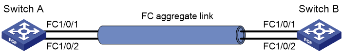
Network configuration
As shown in Figure 16, to increase bandwidth and enhance connection reliability between FCF switches Switch A and Switch B, create an FC aggregate link between Switch A and Switch B.
Procedure
This section describes only the FC link aggregation-related settings, and does not provide the procedure for the other settings.
1. Configure Switch A:
|
|
IMPORTANT: · For information about VSANs, see "Configuring VSANs." · After you assign the FC interfaces at both ends to the FC aggregation group, use the undo shutdown command to bring up the member FC interfaces. |
# Configure the switch to operate in advanced mode, save the configuration, and reboot the switch. (Skip this step if the switch is operating in advanced mode.)
<SwitchA> system-view
[SwitchA] system-working-mode advance
[SwitchA] save
[SwitchA] quit
<SwitchA> reboot
# Configure the switch to operate in FCF mode.
<SwitchA> system-view
[SwitchA] fcoe-mode fcf
# Create VSAN 10.
[SwitchA] vsan 10
[SwitchA-vsan10] quit
# Enable FC and FCoE in VLAN 10 and map VLAN 10 to VSAN 10.
[SwitchA] vlan 10
[SwitchA-vlan10] fcoe enable vsan 10
[SwitchA-vlan10] quit
# Create FC aggregate interface 1. FC aggregation group 1 is automatically created.
[SwitchA] interface san-aggregation 1
# Configure the mode of FC aggregate interface 1 as E.
[SwitchA-SAN-Aggregation1] fc mode e
[SwitchA-SAN-Aggregation1] quit
# Assign FC aggregate interface 1 to VSAN 10 as an access port. Configure the trunk mode of FC aggregate interface 1 as on, and assign FC aggregate interface 1 to VSAN 10 as a trunk port.
[SwitchA-SAN-Aggregation1] port access vsan 10
[SwitchA-SAN-Aggregation1] port trunk mode on
[SwitchA-SAN-Aggregation1] port trunk vsan 10
# Assign FC interfaces FC 1/0/1 and FC 1/0/2 to FC aggregation group 1.
[SwitchA] interface fc 1/0/1
[SwitchA-Fc1/0/1] shutdown
[SwitchA-Fc1/0/1] san-aggregation group 1
The FC mode, trunk mode, trunk VSAN, and access VSAN settings of the FC interface will be lost. Continue? [Y/N]:y
[SwitchA-Fc1/0/1] undo shutdown
[SwitchA-Fc1/0/1] quit
[SwitchA] interface fc 1/0/2
[SwitchA-Fc1/0/2] shutdown
[SwitchA-Fc1/0/2] san-aggregation group 1
The FC mode, trunk mode, trunk VSAN, and access VSAN settings of the FC interface will be lost. Continue? [Y/N]:y
[SwitchA-Fc1/0/2] undo shutdown
[SwitchA-Fc1/0/2] quit
2. Configure Switch B in the same way Switch A is configured.
Verifying the configuration
# Display brief information for FC aggregation group 1 on Switch A.
[SwitchA] display san-aggregate interface san-aggregation 1
* indicates the member port is selected.
Interface State Mode Speed Member port
SAGG1 UP E 8Gbps *Fc1/0/1
*Fc1/0/2
# Display detailed information for FC aggregation group 1 on Switch A.
[SwitchA] display san-aggregation verbose interface san-aggregation 1
Interface SAN-Aggregation1:
State : UP
Mode : E
Speed : 8Gbps
Member port number : 2
Selected port number : 2
Member port State Mode Speed Selected
Fc1/0/1 UP E 4Gbps Y
Fc1/0/2 UP E 4Gbps Y
The output shows that:
· FC 1/0/1 and FC 1/0/2 are Selected and can perform load sharing.
· The speed of the FC aggregate interface is 8 Gbps, which is the sum of the speed of each Selected FC interface.
· When an FC interface fails, the traffic can be transmitted over the other FC interface, which improves the link reliability.
Configuring basic FC and FCoE
Restrictions and guidelines for basic FC and FCoE configuration
To make the FC and FCoE features operate, you must enable FC and FCoE.
Basic FC and FCoE tasks at a glance
To configure basic FC and FCoE, perform the following tasks:
1. Enabling FC and FCoE for a VLAN and mapping the VLAN to a VSAN
2. (Optional.) Setting the FC-MAP value of the FCoE network
3. (Optional.) Setting the FKA advertisement interval value of the FCoE network
4. (Optional.) Setting the FCF priority of the FCoE network
Enabling FC and FCoE for a VLAN and mapping the VLAN to a VSAN
About enabling FC and FCoE
After FC and FCoE is enabled in a VLAN, the following rules apply:
· The VLAN allows only FCoE traffic.
· All member ports in the VLAN are isolated and will not form loops. For this reason, you do not need to enable STP or other loop detection protocols in the VLAN. Otherwise, FCoE links might be blocked.
· A Layer 2 protocol enabled in the VLAN runs only on Ethernet interfaces in the VLAN that are not bound to VFC interfaces.
When you use an FC interface to transmit packets, you must map used VSANs to VLANs and enable FC and FCoE for the VLANs.
When you use a VFC interface to transmit packets, the Ethernet interface bound to the VFC interface might allow multiple VLANs. You must enable FC and FCoE for each of these VLANs and map each VLAN to a different VSAN. Then, the packets from a VSAN are tagged with the mapped VLAN tag and transmitted within the mapped VLAN.
Restrictions and guidelines
FC and FCoE cannot be enabled in VLAN 1.
Do not configure this feature in a VLAN whose VLAN interface resource has been reserved. If you configure this feature in the VLAN, the VFC interfaces assigned to the mapped VSAN as trunk ports cannot come up. For more information about VLAN interface resource reservation, see Layer 2—LAN Switching Command Reference.
VSANs are mapped to VLANs on a one-to-one basis.
The two ends of a link must communicate through the same VSAN. When you use an FC interface to transmit packets, the VSAN at the two ends can be mapped to the same VLAN or different VLANs. When you use a VFC interface to transmit packets, the VSANs at the two ends must be mapped to the same VLAN.
Make sure the Ethernet interface bound to the VFC interface allows the FC- and FCoE-capable VLAN.
Procedure
1. Enter system view.
system-view
2. Enter VLAN view.
vlan vlan-id
3. Enable FC and FCoE for the VLAN and map the VLAN to a VSAN.
fcoe enable [ vsan vsan-id ]
By default, FC and FCoE is disabled for a VLAN.
Setting the FC-MAP value of the FCoE network
About setting the FC-MAP value
An FC-MAP value identifies an FCoE network. Switches in the same FCoE network must have the same FC-MAP value.
Restrictions and guidelines
After an FC-MAP value is set, VFC interfaces perform a FIP renegotiation. The same FC-MAP value is required for two VFC interfaces to negotiate successfully.
Setting the FC-MAP value
1. Enter system view.
system-view
2. Set an FC-MAP value.
fcoe fcmap fc-map
The default setting is 0x0efc00.
Setting the FKA advertisement interval value of the FCoE network
About the FKA advertisement interval
The FKA advertisement interval determines the length of time the switch takes to detect the disconnection of a virtual link.
A switch uses the following process to maintain the virtual link established with a peer switch:
1. The switch sends unsolicited Discovery Advertisements every FKA advertisement interval out of its VFC interfaces in E mode.
The FKA advertisement interval value is carried in unsolicited Discovery Advertisements.
2. After receiving an unsolicited Discovery Advertisement, the peer switch maintains the status of the virtual link and records the FKA advertisement interval value.
If the peer switch fails to receive an unsolicited Discovery Advertisement within 2.5 FKA advertisement intervals, it deletes the virtual link.
A switch uses the following process to maintain the virtual link established with a peer ENode:
1. The switch sends unsolicited Discovery Advertisements every FKA advertisement interval out of its VFC interfaces in F mode.
The FKA advertisement interval value is carried in unsolicited Discovery Advertisements.
2. After receiving an unsolicited Discovery Advertisement, the peer ENode maintains the status of the virtual link and records the FKA advertisement interval value.
If the peer ENode fails to receive an unsolicited Discovery Advertisement within 2.5 FKA advertisement intervals, it deletes the virtual link.
In addition, the ENode sends keepalive frames to the switch every FKA advertisement interval value. This value is obtained from unsolicited Discovery Advertisements received from the switch. After receiving a keepalive frame, the switch maintains the status of the virtual link. If the switch fails to receive a keepalive frame within 2.5 FKA advertisement intervals, it deletes the virtual link.
Restrictions and guidelines
When setting the FKA advertisement interval value on an FCF or NPV switch, use Table 2 as a reference to avoid service disruption.
Table 2 Recommended values for different application scenarios
|
Recommended value |
Application scenarios |
Remarks |
|
Less than 90 seconds |
Connected to servers, storage devices, or third-party switches. |
According to FC-BB-5, the upper limit of the FKA advertisement interval is 90 seconds. In this scenario, a single-MPU FCF switch will experience FCoE traffic disruption during an ISSU reboot because of the following reasons: · This ISSU reboot takes more than 225 (2.5*90) seconds. · The peer deletes the virtual link for failing to receive unsolicited Discovery Advertisements within 225 seconds. |
|
60–90 seconds |
Active/standby switchover on the switch takes more than 2.5 x 60 seconds because of the amount of FCoE configuration. ISSU reboot on a dual-MPU switch takes more than 2.5 x 60 seconds because of the amount of FCoE configuration. |
For more information about ISSU, see Fundamentals Configuration Guide. |
|
300–600 seconds |
ISSU reboot on a single-MPU switch to which no nodes are attached. |
During an ISSU reboot on a single-MPU switch, the switch cannot send unsolicited Discovery Advertisements or keepalive frames. |
Setting the FKA advertisement interval value
1. Enter system view.
system-view
2. Set an FKA advertisement interval value.
fcoe fka-adv-period fka-adv-period
The default setting is 8 seconds.
Setting the FCF priority of the FCoE network
About the FCF priority
The FCF priority includes the system FCF priority and the VFC interface FCF priority.
· System FCF priority—The system FCF priority is used in the fcf priority field in a solicited Discovery Advertisement.
· VFC interface FCF priority—The VFC interface FCF priority is used in the fcf priority field in an unsolicited Discovery Advertisement.
An ENode selects the FCF switch with the highest priority from the FCF switches sending Discovery Advertisements and sends a FLOGI request to the FCF switch for login.
Restrictions and guidelines
The FCF priority takes effect only on VFC interfaces operating in F mode. You can set the FCF priority for a VFC interface operating in E mode. However, the setting does not take effect.
Setting the system FCF priority
1. Enter system view.
system-view
2. Set the system FCF priority.
fcoe global fcf-priority priority
The default setting is 128.
The configuration takes effect on all VFC interfaces operating in F mode.
Setting the VFC interface FCF priority
1. Enter system view.
system-view
2. Enter VFC interface view.
interface vfc interface-number
3. Set the FCF priority for the VFC interface.
fcoe fcf-priority priority
The default setting is 128.
Display and maintenance commands for basic FCoE
Execute display commands in any view.
|
Task |
Command |
|
Display global FCoE configuration. |
display fcoe |
Basic FC and FCoE configuration examples
Example: Configuring basic FC and FCoE by using FC interfaces and VFC interfaces
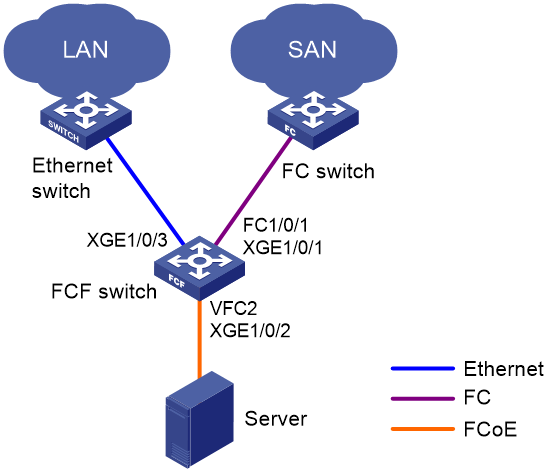
Network configuration
As shown in Figure 17, use FCoE in a data center that combines a LAN and a SAN to reduce the number of devices, network adapters, and cables.
Requirements analysis
To meet the network requirements, perform the following tasks:
· As a best practice to prevent physical loops in a complex LAN, enable STP on the interface that connects the FCF switch to the LAN.
· To prevent loops on the interface that connects the FCF switch to the server, configure the interface as an edge port and enable BPDU guard. An edge port does not participate in spanning tree calculation and can rapidly transition to the forwarding state. When the server logs in to the FCF switch again, traffic loss is minimized for the server.
Procedure
|
|
IMPORTANT: By default, interfaces on the device are disabled (in ADM or Administratively Down state). To have an interface operate, you must use the undo shutdown command to enable that interface. |
Configure the FCF switch as follows:
1. Configure the switch to operate in advanced mode, save the configuration, and reboot the switch. (Skip this step if the switch is operating in advanced mode.)
<Sysname> system-view
[Sysname] system-working-mode advance
[Sysname] save
[Sysname] quit
<Sysname> reboot
2. Configure VLANs and interfaces:
# Create VLANs 10 and 20, which are intended to transmit Ethernet data traffic and storage traffic, respectively.
<Sysname> system-view
[Sysname] vlan 10
[Sysname-vlan10] quit
[Sysname] vlan 20
[Sysname-vlan20] quit
# Enable STP globally.
[Sysname] stp global enable
# Enable BPDU guard globally.
[Sysname] stp bpdu-protection
# Configure FortyGigE 1/0/2 as a hybrid port.
[Sysname] interface fortygige 1/0/2
[Sysname-FortyGigE1/0/2] port link-type hybrid
# Assign FortyGigE 1/0/2 to VLAN 10 as an untagged member.
[Sysname-FortyGigE1/0/2] port hybrid vlan 10 untagged
# Assign FortyGigE 1/0/2 to VLAN 20 as a tagged member.
[Sysname-FortyGigE1/0/2] port hybrid vlan 20 tagged
# Set the PVID to VLAN 10 for FortyGigE 1/0/2.
[Sysname-FortyGigE1/0/2] port hybrid pvid vlan 10
# Disable STP on FortyGigE 1/0/2.
[Sysname-FortyGigE1/0/2] undo stp enable
# Configure FortyGigE 1/0/2 as an edge port.
[Sysname-FortyGigE1/0/2] stp edged-port
# Enable BPDU guard on FortyGigE 1/0/2.
[Sysname-FortyGigE1/0/2] stp port bpdu-protection enable
[Sysname-FortyGigE1/0/2] quit
[Sysname-FortyGigE1/0/2] quit
# Configure FortyGigE 1/0/3 as a trunk port, and assign the interface to VLAN 10.
[Sysname] interface fortygige 1/0/3
[Sysname-FortyGigE1/0/3] port link-type trunk
[Sysname-FortyGigE1/0/3] port trunk permit vlan 10
# Enable STP on FortyGigE 1/0/3.
[Sysname-FortyGigE1/0/3] stp enable
[Sysname-FortyGigE1/0/3] quit
3. Configure DCBX:
# Enable LLDP globally.
[Sysname] lldp global enable
# Create a Layer 2 ACL named DCBX.
[Sysname] acl mac name DCBX
# Configure ACL DCBX to permit FCoE packets (protocol number is 0x8906) and FIP protocol packets (protocol number is 0x8914) to pass through.
[Sysname-acl-mac-DCBX] rule 0 permit type 8906 ffff
[Sysname-acl-mac-DCBX] rule 5 permit type 8914 ffff
[Sysname-acl-mac-DCBX] quit
# Create a class named DCBX, specify the operator of the class as OR, and use ACL DCBX as the match criterion of the class.
[Sysname] traffic classifier DCBX operator or
[Sysname-classifier-DCBX] if-match acl mac name DCBX
[Sysname-classifier-DCBX] quit
# Create a behavior named DCBX, and configure the behavior to mark packets with 802.1p priority value 3.
[Sysname] traffic behavior DCBX
[Sysname-behavior-DCBX] remark dot1p 3
[Sysname-behavior-DCBX] quit
# Create a QoS policy named DCBX, associate class DCBX with traffic behavior DCBX in the QoS policy, and specify that the association apply to DCBX.
[Sysname] qos policy DCBX
[Sysname-qospolicy-DCBX] classifier DCBX behavior DCBX mode dcbx
[Sysname-qospolicy-DCBX] quit
# Enable LLDP and DCBX TLV advertising on FortyGigE 1/0/2.
[Sysname] interface fortygige 1/0/2
[Sysname-FortyGigE1/0/2] lldp enable
[Sysname-FortyGigE1/0/2] lldp tlv-enable dot1-tlv dcbx
# Apply QoS policy DCBX to the outgoing traffic of FortyGigE 1/0/2.
[Sysname-FortyGigE1/0/2] qos apply policy DCBX outbound
4. Configure PFC:
# Enable PFC in auto mode on FortyGigE 1/0/2.
[Sysname-FortyGigE1/0/2] priority-flow-control auto
# Enable PFC for 802.1p priority 3 on the interface.
[Sysname-FortyGigE1/0/2] priority-flow-control no-drop dot1p 3
# Configure the interface to trust the 802.1p priority carried in incoming packets.
[Sysname-FortyGigE1/0/2] qos trust dot1p
[Sysname-FortyGigE1/0/2] quit
5. Configure ETS:
# Configure the 802.1p-local priority mapping table as follows:
¡ Map 802.1p priority value 3 to local precedence 1.
¡ Map the other 802.1p priorities to local precedence 0.
[Sysname] qos map-table dot1p-lp
[Sysname-maptbl-dot1p-lp] import 0 export 0
[Sysname-maptbl-dot1p-lp] import 1 export 0
[Sysname-maptbl-dot1p-lp] import 2 export 0
[Sysname-maptbl-dot1p-lp] import 3 export 1
[Sysname-maptbl-dot1p-lp] import 4 export 0
[Sysname-maptbl-dot1p-lp] import 5 export 0
[Sysname-maptbl-dot1p-lp] import 6 export 0
[Sysname-maptbl-dot1p-lp] import 7 export 0
[Sysname-maptbl-dot1p-lp] quit
# Configure WRR on FortyGigE 1/0/2:
¡ Assign 50% of the interface bandwidth to the FCoE traffic (traffic assigned to queue 1).
¡ Assign 50% of the interface bandwidth to the LAN traffic (traffic assigned to queue 0).
[Sysname] interface fortygige 1/0/2
[Sysname-FortyGigE1/0/2] qos wrr af1 group 1 byte-count 1
[Sysname-FortyGigE1/0/2] qos wrr be group 1 byte-count 1
# Assign the other queues to the SP group on FortyGigE 1/0/2.
[Sysname-FortyGigE1/0/2] qos wrr af2 group sp
[Sysname-FortyGigE1/0/2] qos wrr af3 group sp
[Sysname-FortyGigE1/0/2] qos wrr af4 group sp
[Sysname-FortyGigE1/0/2] qos wrr ef group sp
[Sysname-FortyGigE1/0/2] qos wrr cs6 group sp
[Sysname-FortyGigE1/0/2] qos wrr cs7 group sp
[Sysname-FortyGigE1/0/2] quit
6. Configure FC and FCoE:
# Configure the switch to operate in FCF mode and create VSAN 10.
[Sysname] fcoe-mode fcf
[Sysname] vsan 10
[Sysname-vsan10] quit
# Create VFC 2.
[Sysname] interface vfc 2
# Configure the mode of VFC 2 as F.
[Sysname-Vfc2] fc mode f
# Bind VFC 2 to FortyGigE 1/0/2.
[Sysname-Vfc2] bind interface fortygige 1/0/2
# Assign VFC 2 to VSAN 10 as a trunk port.
[Sysname-Vfc2] port trunk vsan 10
[Sysname-Vfc2] quit
# Change FortyGigE 1/0/1 into FC 1/0/1.
[Sysname] interface fortygige 1/0/1
[Sysname-FortyGigE1/0/1] port-type fc
# Configure the mode of FC 1/0/1 as E.
[Sysname-Fc1/0/1] fc mode e
# Configure FC 1/0/1 to autonegotiate the speed.
[Sysname-Fc1/0/1] speed auto
# Configure FC 1/0/1 to trust the 802.1p priorities carried in incoming packets. This step is required when both FC interfaces and VFC interfaces are used on the switch, so that the VFC interfaces can correctly perform PFC.
[Sysname-Fc1/0/1] qos trust dot1p
# Assign FC 1/0/1 to VSAN 10 as an access port.
[Sysname-Fc1/0/1] port access vsan 10
# Configure the trunk mode of FC 1/0/1 as On, and assign FC 1/0/1 to VSAN 10 as a trunk port.
[Sysname-Fc1/0/1] port trunk mode on
[Sysname-Fc1/0/1] port trunk vsan 10
[Sysname-Fc1/0/1] quit
# Enable FC and FCoE in VLAN 20 and map VLAN 20 to VSAN 10.
[Sysname] vlan 20
[Sysname-vlan20] fcoe enable vsan 10
Example: Configuring basic FCoE by using VFC interfaces
Network configuration
As shown in Figure 18, use FCoE in a data center combining a LAN and a SAN to reduce the number of devices, network adapters, and cables.
Requirements analysis
To meet the network requirements, perform the following tasks:
· As a best practice to prevent physical loops in a complex LAN, enable STP on the interface that connects the FCF switch to the LAN.
· To prevent loops on the interface that connects the FCF switch to the server, configure the interface as an edge port and enable BPDU guard. An edge port does not participate in spanning tree calculation and can rapidly transition to the forwarding state. When the server logs in to the FCF switch again, traffic loss is minimized for the server.
Procedure
|
|
IMPORTANT: By default, interfaces on the device are disabled (in ADM or Administratively Down state). To have an interface operate, you must use the undo shutdown command to enable that interface. |
Configure the FCF switch as follows:
1. Configure the switch to operate in advanced mode, save the configuration, and reboot the switch. (Skip this step if the switch is operating in advanced mode.)
<Sysname> system-view
[Sysname] system-working-mode advance
[Sysname] save
[Sysname] quit
<Sysname> reboot
2. Configure VLANs and interfaces:
# Create VLANs 10 and 20, which are intended to transmit Ethernet data traffic and storage traffic, respectively.
<Sysname> system-view
[Sysname] vlan 10
[Sysname-vlan10] quit
[Sysname] vlan 20
[Sysname-vlan20] quit
# Enable STP globally.
[Sysname] stp global enable
# Enable BPDU guard globally.
[Sysname] stp bpdu-protection
# Configure FortyGigE 1/0/1 as a trunk port, and assign the interface to VLAN 20.
[Sysname] interface fortygige 1/0/1
[Sysname-FortyGigE1/0/1] port link-type trunk
[Sysname-FortyGigE1/0/1] port trunk permit vlan 20
[Sysname-FortyGigE1/0/1] quit
# Configure FortyGigE 1/0/2 as a hybrid port.
[Sysname] interface fortygige 1/0/2
[Sysname-FortyGigE1/0/2] port link-type hybrid
# Assign FortyGigE 1/0/2 to VLAN 10 as an untagged member.
[Sysname-FortyGigE1/0/2] port hybrid vlan 10 untagged
# Assign FortyGigE 1/0/2 to VLAN 20 as a tagged member.
[Sysname-FortyGigE1/0/2] port hybrid vlan 20 tagged
# Set the PVID to VLAN 10 for FortyGigE 1/0/2.
[Sysname-FortyGigE1/0/2] port hybrid pvid vlan 10
# Disable STP on FortyGigE 1/0/2.
[Sysname-FortyGigE1/0/2] undo stp enable
# Configure FortyGigE 1/0/2 as an edge port.
[Sysname-FortyGigE1/0/2] stp edged-port
# Enable BPDU guard on FortyGigE 1/0/2.
[Sysname-FortyGigE1/0/2] stp port bpdu-protection enable
[Sysname-FortyGigE1/0/2] quit
# Configure FortyGigE 1/0/3 as a trunk port, and assign the interface to VLAN 10.
[Sysname] interface fortygige 1/0/3
[Sysname-FortyGigE1/0/3] port link-type trunk
[Sysname-FortyGigE1/0/3] port trunk permit vlan 10
# Enable STP on FortyGigE 1/0/3.
[Sysname-FortyGigE1/0/3] stp enable
[Sysname-FortyGigE1/0/3] quit
3. Configure DCBX:
# Enable LLDP globally.
[Sysname] lldp global enable
# Create a Layer 2 ACL named DCBX.
[Sysname] acl mac name DCBX
# Configure ACL DCBX to permit FCoE packets (protocol number is 0x8906) and FIP protocol packets (protocol number is 0x8914) to pass through.
[Sysname-acl-mac-DCBX] rule 0 permit type 8906 ffff
[Sysname-acl-mac-DCBX] rule 5 permit type 8914 ffff
[Sysname-acl-mac-DCBX] quit
# Create a class named DCBX, specify the operator of the class as OR, and use ACL DCBX as the match criterion of the class.
[Sysname] traffic classifier DCBX operator or
[Sysname-classifier-DCBX] if-match acl mac name DCBX
[Sysname-classifier-DCBX] quit
# Create a behavior named DCBX, and configure the behavior to mark packets with 802.1p priority value 3.
[Sysname] traffic behavior DCBX
[Sysname-behavior-DCBX] remark dot1p 3
[Sysname-behavior-DCBX] quit
# Create a QoS policy named DCBX, associate class DCBX with traffic behavior DCBX in the QoS policy, and specify that the association apply to DCBX.
[Sysname] qos policy DCBX
[Sysname-qospolicy-DCBX] classifier DCBX behavior DCBX mode dcbx
[Sysname-qospolicy-DCBX] quit
# Enable LLDP and DCBX TLV advertising on FortyGigE 1/0/2.
[Sysname] interface fortygige 1/0/2
[Sysname-FortyGigE1/0/2] lldp enable
[Sysname-FortyGigE1/0/2] lldp tlv-enable dot1-tlv dcbx
# Apply QoS policy DCBX to the outgoing traffic of FortyGigE 1/0/2.
[Sysname-FortyGigE1/0/2] qos apply policy DCBX outbound
4. Configure PFC:
# Enable PFC in auto mode on FortyGigE 1/0/2.
[Sysname-FortyGigE1/0/2] priority-flow-control auto
# Enable PFC for 802.1p priority 3 on the interface.
[Sysname-FortyGigE1/0/2] priority-flow-control no-drop dot1p 3
# Configure the interface to trust the 802.1p priority carried in incoming packets.
[Sysname-FortyGigE1/0/2] qos trust dot1p
[Sysname-FortyGigE1/0/2] quit
# Forcibly enable PFC on FortyGigE 1/0/1.
[Sysname-FortyGigE1/0/1] priority-flow-control enable
# Enable PFC for 802.1p priority 3 on the interface.
[Sysname-FortyGigE1/0/1] priority-flow-control no-drop dot1p 3
# Configure the interface to trust the 802.1p priority carried in incoming packets.
[Sysname-FortyGigE1/0/1] qos trust dot1p
[Sysname-FortyGigE1/0/1] quit
5. Configure ETS:
# Configure the 802.1p-local priority mapping table as follows:
¡ Map 802.1p priority value 3 to local precedence 1.
¡ Map the other 802.1p priorities to local precedence 0.
[Sysname] qos map-table dot1p-lp
[Sysname-maptbl-dot1p-lp] import 0 export 0
[Sysname-maptbl-dot1p-lp] import 1 export 0
[Sysname-maptbl-dot1p-lp] import 2 export 0
[Sysname-maptbl-dot1p-lp] import 3 export 1
[Sysname-maptbl-dot1p-lp] import 4 export 0
[Sysname-maptbl-dot1p-lp] import 5 export 0
[Sysname-maptbl-dot1p-lp] import 6 export 0
[Sysname-maptbl-dot1p-lp] import 7 export 0
[Sysname-maptbl-dot1p-lp] quit
# Configure WRR on FortyGigE 1/0/2:
¡ Assign 50% of the interface bandwidth to the FCoE traffic (traffic assigned to queue 1).
¡ Assign 50% of the interface bandwidth to the LAN traffic (traffic assigned to queue 0).
[Sysname] interface fortygige 1/0/2
[Sysname-FortyGigE1/0/2] qos wrr af1 group 1 byte-count 1
[Sysname-FortyGigE1/0/2] qos wrr be group 1 byte-count 1
# Assign the other queues to the SP group on FortyGigE 1/0/2.
[Sysname-FortyGigE1/0/2] qos wrr af2 group sp
[Sysname-FortyGigE1/0/2] qos wrr af3 group sp
[Sysname-FortyGigE1/0/2] qos wrr af4 group sp
[Sysname-FortyGigE1/0/2] qos wrr ef group sp
[Sysname-FortyGigE1/0/2] qos wrr cs6 group sp
[Sysname-FortyGigE1/0/2] qos wrr cs7 group sp
[Sysname-FortyGigE1/0/2] quit
6. Configure FCoE:
# Configure the switch to operate in FCF mode and create VSAN 10.
[Sysname] fcoe-mode fcf
[Sysname] vsan 10
[Sysname-vsan10] quit
# Create VFC 1.
[Sysname] interface vfc 1
# Configure the mode of VFC 1 as E.
[Sysname-Vfc1] fc mode e
# Bind VFC 1 to FortyGigE 1/0/1.
[Sysname-Vfc1] bind interface fortygige 1/0/1
# Assign VFC 1 to VSAN 10 as a trunk port.
[Sysname-Vfc1] port trunk vsan 10
[Sysname-Vfc1] quit
# Create VFC 2.
[Sysname] interface vfc 2
# Configure the mode of VFC 2 as F.
[Sysname-Vfc2] fc mode f
# Bind VFC 2 to FortyGigE 1/0/2.
[Sysname-Vfc2] bind interface fortygige 1/0/2
# Assign VFC 2 to VSAN 10 as a trunk port.
[Sysname-Vfc2] port trunk vsan 10
[Sysname-Vfc2] quit
# Enable FC and FCoE in VLAN 20 and map VLAN 20 to VSAN 10.
[Sysname] vlan 20
[Sysname-vlan20] fcoe enable vsan 10
Configuring VSANs
About VSANs
The virtual storage area network (VSAN) feature breaks a physical SAN into multiple VSANs, and provides more secure, reliable, and flexible services. You can assign interfaces to different VSANs without changing the physical connections of a SAN.
Devices in a VSAN cannot get information about any other VSAN and devices in any other VSAN. Each VSAN performs the following operations independently:
· Selecting a principal switch.
· Assigning domain IDs.
· Running routing protocols.
· Maintaining routing table and FIB table.
· Providing services.
VSAN modes
The interfaces in a VSAN can act as access ports or trunk ports.
· Access port—An access port can belong to only one VSAN.
· Trunk port—A trunk port can belong to multiple VSANs.
FC interfaces and FC aggregate interfaces can act as access ports or trunk ports, depending on negotiation.
VFC interfaces can only act as trunk ports.
Access VSAN
Figure 19 shows a typical access VSAN.
· The ports of blue links on switches (including E_Ports and F_Ports) are configured as access ports and assigned to VSAN 1.
· The ports of purple links are configured as access ports and assigned to VSAN 2.
When servers read the disks, the FC frames are sent from servers to disks as follows:
1. The N_Ports of different servers send FC frames to the F_Ports on FCF Switch A.
2. Switch A searches for the outgoing interfaces in the FIB table of the VSAN that each F_Port belongs to. These F_Ports use different E_Ports as outgoing interfaces.
3. Packets are forwarded out of these E_Ports, and they might travel across multiple VSAN-capable switches to the E_Ports of FCF Switch B.
4. Switch B searches for the outgoing interfaces in the FIB tables of the VSAN that each E_Port belongs to, and forwards them to the F_Ports.
5. The F_Ports send the frames to the N_Ports of different disk devices.
The frames from the disk devices to the server are processed in the same way and finally reach the servers.
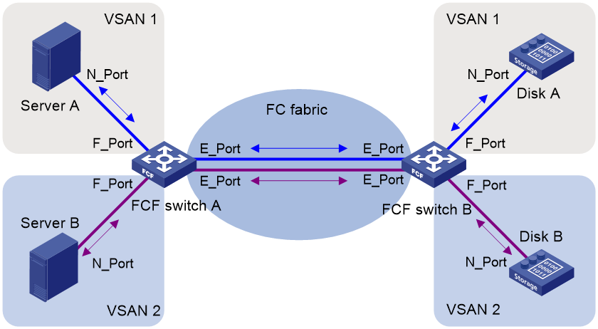
During the transmission procedure, frames are not changed. To support multiple VSANs, a switch must use different physical interfaces. The access VSAN feature does not reduce the number of physical connections. Though different VSANs are isolated from each other, they are physically rather than logically isolated. This mode cannot give full play to the advantages of the VSAN feature.
Trunk VSAN in an FC network
The trunk VSAN feature implements logical isolation among VSANs. A trunk VSAN adds a Virtual Fabric Tagging Header (VFT_Header, also known as VSAN tag) to the FC frames. The VFT_Header contains a VF_ID (also known as VSAN ID) field to indicate the VSAN of the FC frames. In this way, FC frames with different VF_IDs are contained in their respective VSANs, and different VSANs cannot communicate with each other. The trunk VSAN implements physical connectivity and logical isolation in the network.
Figure 20 shows a typical trunk VSAN.
· The F_Ports in blue on switches are configured as access ports and assigned to VSAN 1.
· The F_Ports in purple are configured as access ports and assigned to VSAN 2.
· The E_Ports are configured with trunk VSANs 1 and 2.
When servers read the disks, the FC frames are sent from servers to disks as follows:
1. The N_Ports of different servers send FC frames without VFT_Headers to the F_Ports on FCF switch Switch A.
2. Switch A searches for the outgoing interfaces in the FIB table of the VSAN that each F_Port belongs to. These F_Ports use the same E_Port as the outgoing interface.
3. When the frames are forwarded out of the E_Port, they are tagged with the VFT_Header of VSAN 1 and VSAN 2.
4. The frames travel across multiple VSAN-capable switches to the E_Port of FCF switch Switch B.
5. According to the VFT_Headers, Switch B searches for the outgoing interfaces in the FIB tables of the VSANs, and forwards them to the F_Ports.
6. The F_Ports remove the VFT_Headers and send the frames to the N_Ports of different disk devices.
The frames from the disk devices to the server are processed in the same way and finally reach the servers.
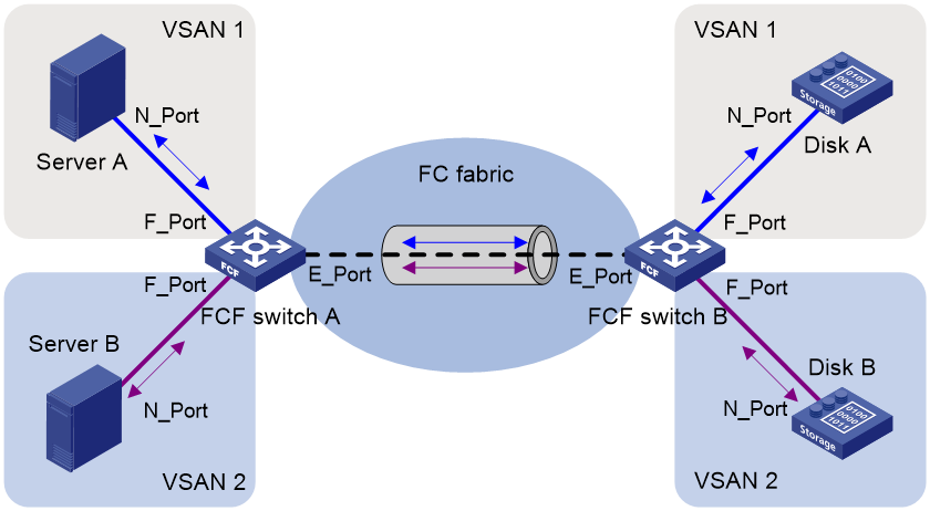
During the transmission process, VFT_Headers are added to and removed from the frames. A switch can use the same physical interface to support multiple VSANs. The trunk VSAN feature reduces the number of physical connections, actually implementing logical isolation in a physical network.
Trunk VSAN in an FCoE network
FCoE transports FC over Ethernet. In an FCoE network:
· VSANs in FC must be mapped to VLANs as configured by the user.
· The FIB table for a VSAN is also stored on the relevant VLAN.
FCoE frames use VLAN_Headers to replace VFT_Headers in FC frames and are forwarded based on the VLAN IDs in VLAN_Headers.
A VFC interface can only act as a trunk port. The bound Ethernet interface must also be configured as a trunk port. Its trunk VLAN list must include the VLANs mapped to each VSAN in the trunk VSAN list of the VFC interface. An FCoE frame transmitted from a VFC interface can use the VLAN ID in VLAN_Header to identify the VLAN to which it belongs.
VSAN mode negotiation
FC interfaces and FC aggregate interfaces can act as access ports or trunk ports, depending on link negotiation. VFC interfaces can only act as trunk ports and do not require negotiation.
Link negotiation involves a series of protocols. The Exchange Virtual Fabrics Parameters (EVFP) protocol determines the VSAN mode that applies.
The EVFP negotiation determines the VSAN mode based on the following settings on both ends of a link:
· Trunk mode—The trunk mode can be auto (default), on, or off.
· Access VSAN—Indicates the VSAN to which the interface is added as an access port, which is VSAN 1 by default.
· Trunk VSAN list—Indicates the VSANs to which the interface is added as a trunk port. By default, the VSAN list is empty.
The EVFP negotiation process is as follows:
1. The interface at each end sends its trunk mode, access VSAN, and trunk VSAN list to the peer.
2. The two ends negotiate the VSAN tagging mode according to the trunk modes.
Table 3 shows the negotiation rules.
Table 3 VSAN tagging mode negotiation rules
|
Trunk mode of the peer end (right) |
Off |
On |
Auto |
|
Trunk mode of the local end (below) |
|||
|
Off |
Non Tagging |
Non Tagging |
Non Tagging |
|
On |
Non Tagging |
Tagging |
Tagging |
|
Auto |
Non Tagging |
Tagging |
Non Tagging |
3. The two ends determine whether to act as access or trunk ports according to the negotiation result, their access VSANs, and their trunk VSAN lists.
¡ If the negotiation result is Non Tagging, EVFP checks whether both ends have the same access VSAN.
- If the two ends have different access VSANs, EVFP considers the access VSAN configurations as configuration errors.
- If the two ends have the same access VSAN, the two interfaces both act as access ports. The configured trunk VSAN list does not take effect. The two interfaces can send and receive only FC frames without VFT_Headers.
¡ If the negotiation result is Tagging, EVFP checks whether the trunk VSAN lists of both ends overlap and have common VSANs.
- If the two ends do not have common VSANs, EVFP considers the trunk VSAN list configurations as configuration errors.
- If the two ends have common VSANs, the two interfaces both act as trunk ports in the common VSANs. The configured access VSAN does not take effect.
As shown in Figure 21:
· The interfaces on FCF switch A are configured with trunk VSANs 1, 2, 3, and 4.
· The interfaces on FCF switch B are configured with trunk VSANs 1, 2, and 3.
After negotiation, the link connecting the two switches can only transmit FC frames with VF_ID 1, 2, or 3 in the VFT_Headers. The link cannot transmit frames without VFT_Headers or frames with VFT_Headers whose VF_ID fields are not the common VSANs of the two switches.
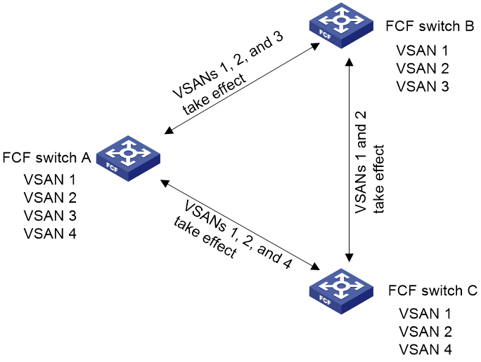
Restrictions and guidelines: VSAN configuration
You must configure the following settings for an FC interface or FC aggregate interface, whether it is assigned to a VSAN as an access port or a trunk port:
· Configure an access VSAN. The access VSAN can be VSAN 1 or any other VSAN.
· Map the access VSAN to a VLAN.
Otherwise, the FC interface or FC aggregate interface fails to perform negotiation and cannot come up.
VSAN tasks at a glance
To configure a VSAN for an FC interface or FC aggregate interface, perform the following tasks:
2. (Optional.) Configuring the trunk mode
This task is required on both ends if the trunk mode of either the local or peer FC interface is on.
To configure a VSAN for a VFC interface, perform the following tasks:
Creating a VSAN
Restrictions and guidelines
By default, a system-defined VSAN (VSAN 1) exists. You cannot create or delete VSAN 1. You can create VSANs 2 to 3839.
The switch supports a maximum of 256 VSANs (including VSAN 1).
By default, registered N_Ports in a VSAN belong to the default zone and cannot access one another. You can allow these N_Ports to access one another by configuring the default zone policy. For more information about zones, see "Configuring FC zones."
Procedure
1. Enter system view.
system-view
2. Create a VSAN and enter VSAN view.
vsan vsan-id [ name vsan-name ]
By default, VSAN 1 exists with the name VSAN0001.
Configuring the trunk mode
Restrictions and guidelines
FC interfaces and FC aggregate interfaces support the trunk mode configuration. VFC interfaces can work only as trunk ports and do not support the trunk mode configuration.
If the switch connects to a node through an FC interface or FC aggregate interface, as a best practice, assign the interface to a VSAN as an access port. If you assign the interface to a VSAN as a trunk port, node login might be affected.
Procedure
1. Enter system view.
system-view
2. Enter FC interface view or FC aggregate interface view.
interface { fc | san-aggregation } interface-number
3. Configure the trunk mode of the interface.
port trunk mode { auto | off | on }
By default, the trunk mode of an interface is auto.
Configuring an access VSAN
Restrictions and guidelines for configuring an access VSAN
You can assign interfaces to a VSAN as access ports one by one in interface view. Alternatively, you can assign multiple interfaces to a VSAN as access ports by configuring an interface list in VSAN view. If you assign an interface to different VSANs by using the two methods, the most recent configuration takes effect.
Prerequisites
Before assigning an interface to a VSAN as an access port, you must create the VSAN.
Assigning an interface to a VSAN as an access port
1. Enter system view.
system-view
2. Enter FC interface view or FC aggregate interface view.
interface { fc | san-aggregation } interface-number
3. Assign the interface to a VSAN as an access port.
port access vsan vsan-id
By default, an interface belongs to VSAN 1 as an access port.
Assigning interfaces to a VSAN as access ports in bulk
1. Enter system view.
system-view
2. Enter VSAN view.
vsan vsan-id
3. Assign a list of interfaces to the VSAN as access ports.
port interface-list
By default, an interface belongs to VSAN 1 as an access port.
Configuring a trunk VSAN
About this task
FC interfaces, FC aggregate interfaces, and VFC interfaces can be assigned to multiple VSANs as trunk ports.
If you assign an interface to VSANs as a trunk port multiple times, the new configuration does not overwrite the old configurations. The final trunk VSAN list is the union of all the VSANs to which you have assigned the interface.
Prerequisites
Before assigning an interface to a VSAN as a trunk port, you must create the VSAN.
Restrictions and guidelines
FC interfaces and FC aggregate interfaces perform VSAN mode negotiation in the access VSAN. When you configure a trunk VSAN for an FC interface or FC aggregate interface, you must also map the access VSAN to a VLAN. The default access VSAN is VSAN 1 for FC interfaces and FC aggregate interfaces.
Procedure
1. Enter system view.
system-view
2. Enter FC interface, FC aggregate interface, or VFC interface view.
interface { fc | san-aggregation | vfc } interface-number
3. Assign the interface to the specified VSANs as a trunk port so that the interface allows the specified VSANs to pass through.
port trunk vsan vsan-id-list
By default, an interface does not belong to any VSAN (including VSAN 1) as a trunk port.
Display and maintenance commands for VSANs
Execute display commands in any view.
|
Task |
Command |
|
Display the member ports of VSANs. |
display vsan [ vsan-id ] port-member |
VSAN configuration examples
Example: Configuring VSANs by using FC interfaces
Network configuration
As shown in Figure 22, configure the SAN to meet the following requirements:
· Server A can read and write only the data of Disk A and Disk B.
· Server B can read and write only the data of Disk C.
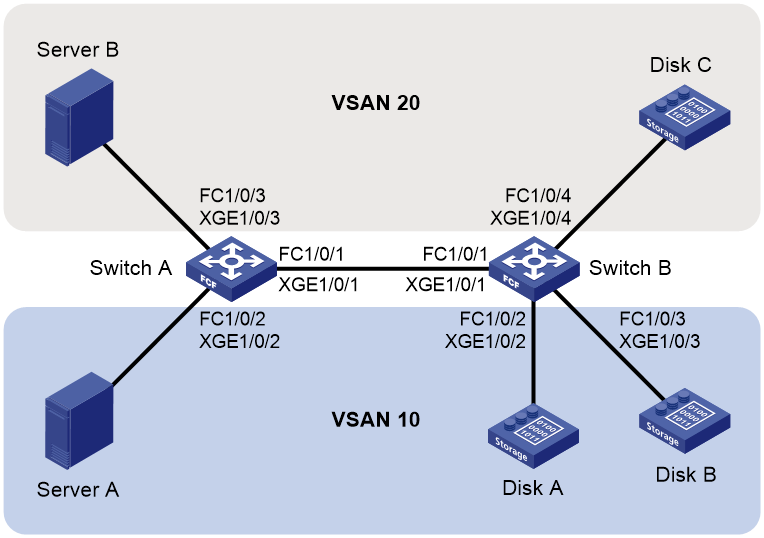
Procedure
|
|
IMPORTANT: By default, interfaces on the device are disabled (in ADM or Administratively Down state). To have an interface operate, you must use the undo shutdown command to enable that interface. |
This section describes only the VSAN configurations.
1. Configure Switch A:
# Configure the switch to operate in advanced mode, save the configuration, and reboot the switch. (Skip this step if the switch is operating in advanced mode.)
<SwitchA> system-view
[SwitchA] system-working-mode advance
[SwitchA] save
[SwitchA] quit
<SwitchA> reboot
# Configure the switch to operate in FCF mode.
<SwitchA> system-view
[SwitchA] fcoe-mode fcf
# Create VSAN 10, and allow the zone members in the default zone to access one another.
[SwitchA] vsan 10
[SwitchA-vsan10] zone default-zone permit
[SwitchA-vsan10] quit
# Create VSAN 20, and allow the zone members in the default zone to access one another.
[SwitchA] vsan 20
[SwitchA-vsan20] zone default-zone permit
[SwitchA-vsan20] quit
# Change FortyGigE 1/0/1 into FC 1/0/1.
[SwitchA] interface fortygige 1/0/1
[SwitchA-FortyGigE1/0/1] port-type fc
# Configure the mode of FC 1/0/1 as E.
[SwitchA-Fc1/0/1] fc mode e
# Configure FC 1/0/1 to autonegotiate the speed.
[SwitchA-Fc1/0/1] speed auto
# Assign FC 1/0/1 to VSAN 10 as an access port.
[SwitchA-Fc1/0/1] port access vsan 10
# Configure the trunk mode of FC 1/0/1 as On, and assign FC 1/0/1 to VSANs 10 and 20 as a trunk port.
[SwitchA-Fc1/0/1] port trunk mode on
[SwitchA-Fc1/0/1] port trunk vsan 10 20
[SwitchA-Fc1/0/1] quit
# Change FortyGigE 1/0/2 into FC 1/0/2.
[SwitchA] interface fortygige 1/0/2
[SwitchA-FortyGigE1/0/2] port-type fc
# Configure the mode of FC 1/0/2 as F.
[SwitchA-Fc1/0/2] fc mode f
# Configure FC 1/0/2 to autonegotiate the speed.
[SwitchA-Fc1/0/2] speed auto
# Assign FC 1/0/2 to VSAN 10 as an access port.
[SwitchA-Fc1/0/2] port access vsan 10
[SwitchA-Fc1/0/2] quit
# Change FortyGigE 1/0/3 into FC 1/0/3.
[SwitchA] interface fortygige 1/0/3
[SwitchA-FortyGigE1/0/3] port-type fc
# Configure the mode of FC 1/0/3 as F.
[SwitchA-Fc1/0/3] fc mode f
# Configure FC 1/0/3 to autonegotiate the speed.
[SwitchA-Fc1/0/3] speed auto
# Assign FC 1/0/3 to VSAN 20 as an access port.
[SwitchA-Fc1/0/3] port access vsan 20
[SwitchA-Fc1/0/3] quit
# Enable FC and FCoE in VLAN 10 and map VLAN 10 to VSAN 10.
[SwitchA] vlan 10
[SwitchA-vlan10] fcoe enable vsan 10
[SwitchA-vlan10] quit
# Enable FC and FCoE in VLAN 20 and map VLAN 20 to VSAN 20.
[SwitchA] vlan 20
[SwitchA-vlan20] fcoe enable vsan 20
[SwitchA-vlan20] quit
2. Configure Switch B in the same way Switch A is configured.
Verifying the configuration
# Display member interfaces of each VSAN on switches, for example, Switch A.
[SwitchA] display vsan port-member
VSAN 1:
Access Ports:
Trunk Ports:
VSAN 10:
Access Ports:
Fc1/0/2
Trunk Ports:
Fc1/0/1
VSAN 20:
Access Ports:
Fc1/0/3
Trunk Ports:
Fc1/0/1
Example: Configuring VSANs by using VFC interfaces
Network configuration
As shown in Figure 23, configure the VSANs to meet the following requirements:
· Server A can read and write only the data of Disk A and Disk B.
· Server B can read and write only the data of Disk C.
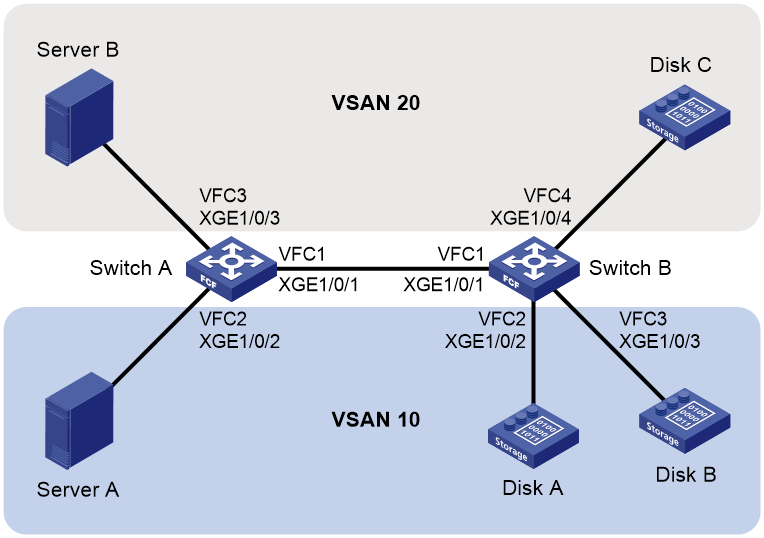
Procedure
|
|
IMPORTANT: By default, interfaces on the device are disabled (in ADM or Administratively Down state). To have an interface operate, you must use the undo shutdown command to enable that interface. |
This section describes only the VSAN configurations.
1. Configure Switch A:
# Configure the switch to operate in advanced mode, save the configuration, and reboot the switch. (Skip this step if the switch is operating in advanced mode.)
<SwitchA> system-view
[SwitchA] system-working-mode advance
[SwitchA] save
[SwitchA] quit
<SwitchA> reboot
# Configure the switch to operate in FCF mode.
<SwitchA> system-view
[SwitchA] fcoe-mode fcf
# Create VSAN 10, and allow the zone members in the default zone to access one another.
[SwitchA] vsan 10
[SwitchA-vsan10] zone default-zone permit
[SwitchA-vsan10] quit
# Create VSAN 20, and allow the zone members in the default zone to access one another.
[SwitchA] vsan 20
[SwitchA-vsan20] zone default-zone permit
[SwitchA-vsan20] quit
# Create VFC 1.
[SwitchA] interface vfc 1
# Configure the mode of VFC 1 as E.
[SwitchA-Vfc1] fc mode e
# Bind VFC 1 to FortyGigE 1/0/1.
[SwitchA-Vfc1] bind interface fortygige 1/0/1
# Assign VFC 1 to VSAN 10 and VSAN 20 as a trunk port.
[SwitchA-Vfc1] port trunk vsan 10 20
[SwitchA-Vfc1] quit
# Configure FortyGigE 1/0/1 as a trunk port, and assign the port to VLAN 10 and VLAN 20.
[SwitchA] interface fortygige 1/0/1
[SwitchA-FortyGigE1/0/1] port link-type trunk
[SwitchA-FortyGigE1/0/1] port trunk permit vlan 10 20
[SwitchA-FortyGigE1/0/1] quit
# Create VFC 2.
[SwitchA] interface vfc 2
# Configure the mode of VFC 2 as F.
[SwitchA-Vfc2] fc mode f
# Bind VFC 2 to FortyGigE 1/0/2.
[SwitchA-Vfc2] bind interface fortygige 1/0/2
# Assign VFC 2 to VSAN 10 as a trunk port.
[SwitchA-Vfc2] port trunk vsan 10
[SwitchA-Vfc2] quit
# Configure FortyGigE 1/0/2 as a trunk port, and assign the port to VLAN 10.
[SwitchA] interface fortygige 1/0/2
[SwitchA-FortyGigE1/0/2] port link-type trunk
[SwitchA-FortyGigE1/0/2] port trunk permit vlan 10
[SwitchA-FortyGigE1/0/2] quit
# Create VFC 3.
[SwitchA] interface vfc 3
# Configure the mode of VFC 3 as F.
[SwitchA-Vfc3] fc mode f
# Bind VFC 3 to FortyGigE 1/0/3.
[SwitchA-Vfc3] bind interface fortygige 1/0/3
# Assign VFC 3 to VSAN 20 as a trunk port.
[SwitchA-Vfc3] port trunk vsan 20
[SwitchA-Vfc3] quit
# Configure FortyGigE 1/0/3 as a trunk port, and assign the port to VLAN 20.
[SwitchA] interface fortygige 1/0/3
[SwitchA-FortyGigE1/0/3] port link-type trunk
[SwitchA-FortyGigE1/0/3] port trunk permit vlan 20
[SwitchA-FortyGigE1/0/3] quit
# Enable FC and FCoE in VLAN 10 and map VLAN 10 to VSAN 10.
[SwitchA] vlan 10
[SwitchA-vlan10] fcoe enable vsan 10
[SwitchA-vlan10] quit
# Enable FC and FCoE in VLAN 20 and map VLAN 20 to VSAN 20.
[SwitchA] vlan 20
[SwitchA-vlan20] fcoe enable vsan 20
[SwitchA-vlan20] quit
2. Configure Switch B in the same way Switch A is configured.
Verifying the configuration
# Display member interfaces of each VSAN on switches, for example, Switch A.
[SwitchA] display vsan port-member
VSAN 1:
Access Ports:
Trunk Ports:
VSAN 10:
Access Ports:
Trunk Ports:
Vfc1
Vfc2
VSAN 20:
Access Ports:
Trunk Ports:
Vfc1
Vfc3
Building a fabric
About fabrics
A fabric transmits data for servers and disk devices. When building a fabric, you must perform the following tasks:
· Assign a domain ID to each FCF switch in the fabric.
· Assign an FC address to each node connected to the fabric.
Fabric building modes
You can build a fabric through one of the following modes:
· Dynamic mode—A principal switch is automatically selected to assign domain IDs to all switches in the fabric, and then each switch assigns FC addresses to the N_Ports connected to it. Dynamic mode enables centralized network management and is applicable to large-sized networks.
· Static mode—You must manually assign domain IDs to all switches in the fabric, and then each switch assigns FC addresses to the N_Ports connected to it. Static mode avoids network flapping, but it is applicable only to simple, small-sized networks. This mode does not include a principal switch selection process.
Figure 24 Fabric building workflows
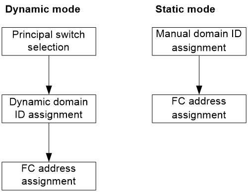
Principal switch selection
During the dynamic fabric building process, it is the principal switch that assigns domain IDs to all switches in the network.
The switch with the highest priority is selected as the principal switch. When multiple switches have the same priority, the switch with the smallest WWN is selected.
The principal switch selection process is as follows:
1. When the principal switch selection starts, each switch performs the following operations:
¡ Considers itself to be the principal switch.
¡ Records itself in the principal switch information.
¡ Starts the Principal Switch Selection Timer (PSST), which is 10 seconds.
2. Before the PSST times out, the switches exchange packets carrying the principal switch information to select a principal switch.
3. On receiving a packet carrying principal switch information, a switch compares the priority and WWN of the principal switch carried in the packet with those locally recorded. The switch replaces the locally recorded principal switch information with the information recorded in the packet when any of the following conditions exist:
¡ The priority carried in the packet is higher.
¡ The priority in the packet is the same and the WWN is smaller.
Also, it notifies the other switches of the change. Finally, all switches in the network make an agreement on the principal switch.
4. When the PSST times out, if the locally recorded principal switch information is the local switch, the switch becomes the principal switch.
After the principal switch is selected, the WWN of the principal switch becomes the fabric name.
|
|
NOTE: During the process, if a switch receives a packet that updates the principal switch information, the switch must record the E_Port receiving the packet. The link relevant to this E_Port is called the upstream principal link. |
Domain ID assignment
A domain represents a switch and all N_Ports connected to the switch. Each domain must have a domain ID.
Domain IDs can be manually configured or automatically assigned for FCF switches.
· When you manually configure static domain IDs, you must assign a unique domain ID to each switch in the fabric.
· When domain IDs are dynamically assigned, the fabric configuration process is performed to select a principal switch and assign domain IDs. After the principal switch is selected, the principal switch assigns domain IDs to all switches in the fabric. After the fabric configuration process, each switch has a unique domain ID.
Dynamic domain ID assignment
The dynamic domain ID assignment process is as follows:
1. The principal switch assigns itself a domain ID.
¡ If you have configured a domain ID on the principal switch, the principal switch assigns itself the configured domain ID.
¡ If you have not configured a domain ID on the principal switch, the principal switch assigns itself a random domain ID.
2. The principal switch notifies its downstream switches to request domain IDs from it.
3. A downstream switch requests a domain ID from the principal switch.
If the downstream switch is configured with a domain ID, it sends the configured domain ID in its request.
4. The principal switch assigns a domain ID to the downstream switch according to the following rules:
¡ If the downstream switch requests a configured domain ID that is available, the principal switch assigns the configured domain ID.
¡ The principal switch assigns a random domain ID when one of the following conditions exists:
- The downstream switch does not request a configured domain ID.
- The configured domain ID is not available.
¡ If all available domain IDs have been assigned, the principal switch notifies the downstream switch that no domain ID can be assigned.
5. After the downstream switch receives the domain ID assignment notification from the principal switch, it works according to the following rules:
¡ The downstream switch isolates its upstream principal link and brings down the relevant interface when any of the following conditions exist:
- The downstream switch has been configured with a static domain ID different from the one assigned by the principal switch.
- The principal switch notifies the downstream switch that no domain ID can be assigned.
For more information about domain ID types, see "Configuring a domain ID."
¡ If none of the preceding conditions exist, the downstream switch performs the following operations:
- Accepts the domain ID assigned by the principal switch and records it in a hidden file.
If no new domain ID is configured when the downstream switch requests a domain ID next time, the recorded domain ID is sent in the request. To avoid writing domain IDs to the hidden file frequently, the switch starts a 5-second timer upon a domain ID change. The switch records the assigned domain ID in the hidden file when the timer expires. If a reboot is required after a domain ID change, reboot the switch 5 seconds after the domain ID change.
- Notifies its downstream switches to request domain IDs from the principal switch.
6. Steps 2 through 5 are repeated until all downstream switches have been assigned domain IDs.
|
|
NOTE: During the process, if a switch receives a domain ID request on an E_Port, the switch records the E_Port. The link relevant to this E_Port is called the downstream principal link. |
FC address assignment
After a switch obtains a domain ID, it assigns FC addresses to N_Ports directly connected.
The Domain_ID field in the FC address is the domain ID of the switch, and it does not need assignment.
The switch assigns FC addresses to N_Ports according to the following rules:
· If you have bound an FC address to an N_Port, the switch assigns the bound FC address in the entry to the N_Port.
· If you have configured a desired FC address for an N_Port on the node, the switch assigns the desired FC address, if available.
· The switch assigns the smallest available area ID and port ID to the N_Port when one of the following conditions exists:
¡ The N_Port itself does not have a desired FC address.
¡ The desired FC address is unavailable.
Restrictions and guidelines: Building a fabric
As a best practice, use dynamic mode for large networks to facilitate centralized management and use static mode for small networks to avoid network flapping.
Fabric building tasks at a glance
Building a fabric statically
To build a fabric statically, perform the following tasks:
1. Disabling the fabric configuration feature
2. Configure basic fabric settings
¡ Configuring an allowed domain ID list
3. (Optional.) Configuring the persistent FC address feature
4. (Optional.) Setting the maximum number of logged-in nodes
5. (Optional.) Setting fabric timers
6. (Optional.) Configuring RSCN aggregation
7. (Optional.) Configuring and obtaining FC4 information of nodes
8. (Optional.) Configuring Smart SAN
Building a fabric dynamically
To build a fabric dynamically, perform the following tasks:
1. Enabling the fabric configuration feature
2. Configure basic fabric settings
¡ Configuring an allowed domain ID list
3. (Optional.) Configuring the persistent FC address feature
4. (Optional.) Setting the maximum number of logged-in nodes
5. (Optional.) Setting fabric timers
6. (Optional.) Configuring the fabric reconfiguration feature
7. (Optional.) Configuring an interface to reject incoming RCF requests
8. (Optional.) Enabling SNMP notifications for the fabric or name service module
9. (Optional.) Configuring RSCN aggregation
10. (Optional.) Configuring and obtaining FC4 information of nodes
11. (Optional.) Configuring Smart SAN
Enabling or disabling the fabric configuration feature
Restrictions and guidelines for enabling or disabling the fabric configuration feature
To dynamically build a fabric, you must enable the fabric configuration feature on switches. After you enable the fabric configuration feature on FCF switches, the switches exchange messages to select the principal switch. Then, the principal switch dynamically assigns domain IDs to all switches in the fabric.
To statically build a fabric, you must disable the fabric configuration feature on switches and manually configure a unique domain ID for each switch. After you disable the fabric configuration feature on FCF switches, the switches will not select a principal switch and cannot obtain domain IDs dynamically.
Enabling the fabric configuration feature
1. Enter system view.
system-view
2. Enter VSAN view.
vsan vsan-id
3. Enable the fabric configuration feature for the VSAN.
domain configure enable
By default, the fabric configuration feature is enabled.
Disabling the fabric configuration feature
1. Enter system view.
system-view
2. Enter VSAN view.
vsan vsan-id
3. Disable the fabric configuration feature for the VSAN.
undo domain configure enable
By default, the fabric configuration feature is enabled.
Setting a fabric name
About this task
You can set a fabric name for each VSAN on an FCF switch. The default fabric name for a VSAN is the WWN of the switch.
Restrictions and guidelines
Set the fabric names only when you build a fabric statically. Make sure the same fabric name is set for a VSAN on all switches in the fabric. In a dynamically built fabric, each VSAN uses the WWN of the principal switch as the fabric name.
Procedure
1. Enter system view.
system-view
2. Enter VSAN view.
vsan vsan-id
3. Set a fabric name for the VSAN.
fabric-name name
The default fabric name for a VSAN is the WWN of the switch.
Setting the switch priority
About this task
The FCF switch with the highest priority (smallest priority value) will be selected as the principal switch.
The priority is set on a per-VSAN basis, and one FCF switch can have different priorities in different VSANs.
In a stable fabric, the set priority does not take effect immediately, and the running priority of a switch might be different from the set priority. To make the set priority take effect, use the domain restart disruptive command to initiate a disruptive reconfiguration. After a disruptive reconfiguration, the running priority might be different from the set priority, depending on the set priority value, as shown in Table 4.
Table 4 Set priority and running priority mappings
|
Set priority |
Running priority |
|
≤ 2 |
· Principal switch—Same as the set priority. · Non-principal switch—3. |
|
> 2 |
· Principal switch—2. · Non-principal switch—Same as the set priority. |
Procedure
1. Enter system view.
system-view
2. Enter VSAN view.
vsan vsan-id
3. Set the switch priority in the VSAN.
priority priority
The default setting is 128.
Configuring an allowed domain ID list
About this task
To successfully configure an allowed domain ID list on the principal switch, make sure all assigned and locally configured domain IDs are included in the list. After you configure an allowed domain ID list, the principal switch assigns only domain IDs available in the allowed list.
To successfully configure an allowed domain ID list on a non-principal switch, make sure the runtime domain ID of the switch is included in the allowed list. After you configure an allowed domain ID list on a non-principal switch, the following rules apply:
· The locally configured domain ID must be included in the allowed list. Otherwise, the domain ID configuration fails.
· The principal switch must assign a domain ID that is included in the allowed list of the non-principal switch. Otherwise, the non-principal switch refuses the assigned domain ID and isolates its interface connected to the principal switch.
Restrictions and guidelines
As a best practice, configure the same allowed domain ID list for all switches in a VSAN.
Procedure
1. Enter system view.
system-view
2. Enter VSAN view.
vsan vsan-id
3. Configure an allowed domain ID list for the VSAN.
allowed-domain-id domain-id-list
By default, the allowed domain IDs are 1 to 239.
Configuring a domain ID
About this task
In different scenarios, the configured domain ID has different meanings.
· In a statically built fabric, a switch uses the configured domain ID as its actual domain ID. You must manually configure a domain ID for each switch.
· In a dynamically built fabric, a switch requests the configured domain ID from the principal switch but might be assigned a different domain ID. Configuring a domain ID is optional in a dynamically built fabric.
The configured domain ID can be static or preferred.
· In a statically built fabric, the two types make no difference.
· In a dynamically built fabric, when the assigned domain ID and requested domain ID for a non-principal switch are different, the following rules apply:
¡ If the configured domain ID is preferred, the non-principal switch accepts the domain ID assigned by the principal switch.
¡ If the configured domain ID is static, the non-principal switch isolates the upstream principal link and refuses the assigned domain ID.
Restrictions and guidelines
As a best practice, configure domain IDs of the same type for all switches in a VSAN.
Procedure
1. Enter system view.
system-view
2. Enter VSAN view.
vsan vsan-id
3. Configure a domain ID for the switch in the VSAN.
domain-id domain-id { preferred | static }
By default, the domain ID is 0 preferred.
Configuring the persistent FC address feature
About this task
The persistent FC address feature binds WWNs of N_Ports or NP_Ports to FC addresses in persistent FC address entries. When an N_Port or NP_Port logs in to the fabric for the first time or across switch reboots, it is assigned the bound FC address. Persistent FC address entries include the following types:
· Static entries—Can only be manually configured.
· Dynamic entries—Can be manually configured or dynamically learned. When an N_Port or NP_Port logs in and is assigned an FC address, the system learns the WWN and binds the assigned FC address to the WWN. The N_Port or NP_Port is assigned the bound FC address across device reboots if you have saved the configuration.
Restrictions and guidelines
A WWN can be bound to only one FC address, and vice versa. If the WWN has been assigned another FC address or the FC address has been assigned to another WWN, a persistent FC address entry cannot be created.
Manually configured persistent FC address entries take effect only when the persistent FC address feature is enabled.
Procedure
1. Enter system view.
system-view
2. Enter VSAN view.
vsan vsan-id
3. Enable the persistent FC address feature in the VSAN.
fcid persistent enable
By default, the persistent FC address feature is enabled.
4. (Optional.) Configure a persistent FC address entry.
wwn wwn-value fcid fcid-value [ dynamic ]
Setting the maximum number of logged-in nodes
About this task
Logged-in nodes consume ACL resources. To save ACL resources, you can set the maximum number of logged-in nodes allowed in a VSAN. The number of logged-in nodes is the number of directly connected NPV switches plus the number of logged-in servers and disks.
If the number of logged-in nodes exceeds the set maximum number, no logged-in nodes will be logged out. However, any new nodes cannot log in. You can manually log out nodes by shutting down interfaces connected to these nodes.
Restrictions and guidelines
The maximum number of logged-in nodes allowed depends on both this feature and hardware ACL resources. When hardware ACL resources are exhausted, any new nodes cannot log in.
Procedure
1. Enter system view.
system-view
2. Enter VSAN view.
vsan vsan-id
3. Set the maximum number of logged-in nodes allowed in the VSAN.
fc login-limit max-number
By default, the number of logged-in nodes allowed in a VSAN is not limited.
Setting fabric timers
About fabric timers
The fabric operation involves the following timers:
· Distributed service timeout period.
· Error detection timeout period.
· Resource allocation timeout period.
For more information about these timers, see FC-related protocols and standards.
Restrictions and guidelines
You can set fabric timers in one of the following views:
· System view—The setting takes effect on all VSANs.
· VSAN view—The setting takes effect only on the VSAN.
If you set a fabric timer in both system view and VSAN view, the setting in VSAN view applies to the VSAN.
Setting fabric timers in system view
1. Enter system view.
system-view
2. Set the global distributed service timeout period.
fc timer distributed-services value
The default setting is 5000 milliseconds.
3. Set the global error detection timeout period.
fc timer error-detect value
The default setting is 2000 milliseconds.
4. Set the global resource allocation timeout period.
fc timer resource-allocation value
The default setting is 10000 milliseconds.
Setting fabric timers in VSAN view
1. Enter system view.
system-view
2. Enter VSAN view.
vsan vsan-id
3. Set the distributed service timeout period for the VSAN.
timer distributed-services value
The default setting is 5000 milliseconds.
4. Set the error detection timeout period for the VSAN.
timer error-detect value
The default setting is 2000 milliseconds.
5. Set the resource allocation timeout period for the VSAN.
timer resource-allocation value
The default setting is 10000 milliseconds.
Configuring the fabric reconfiguration feature
About fabric reconfiguration
A fabric reconfiguration can be initiated manually or automatically by using the automatic reconfiguration feature.
A fabric reconfiguration applies to fabrics dynamically built and triggers a principal switch selection process.
A fabric reconfiguration can be disruptive or nondisruptive.
· Disruptive reconfiguration—Floods Reconfigure Fabric (RCF) frames throughout the fabric, and notifies all switches to perform a disruptive reconfiguration. During the reconfiguration procedure, each switch clears all data and performs renegotiation.
· Nondisruptive reconfiguration—Floods Build Fabric (BF) frames throughout the fabric, and notifies all switches to perform a nondisruptive reconfiguration. During the reconfiguration procedure, each switch tries to save the last running data for its domain ID to remain unchanged. Thus, data transmission in the fabric is not disrupted.
You can manually perform a disruptive reconfiguration after an interface is isolated or the priority of a switch is modified in a fabric.
A disruptive reconfiguration is automatically performed if the domain ID lists overlap when two fabrics are merged.
A nondisruptive reconfiguration is automatically performed when one of the following conditions exists:
· When two fabrics are merged, the principal switch information of the two fabrics is different, and the domain ID lists are not empty and do not overlap.
· A principal link in a fabric goes down.
Enabling the automatic reconfiguration feature
1. Enter system view.
system-view
2. Enter VSAN view.
vsan vsan-id
3. Enable the automatic reconfiguration feature.
domain auto-reconfigure enable
By default, the automatic reconfiguration feature is disabled.
Manually initiating a fabric reconfiguration
1. Enter system view.
system-view
2. Enter VSAN view.
vsan vsan-id
3. Manually initiate a fabric reconfiguration.
domain restart [ disruptive ]
|
|
CAUTION: If you specify the disruptive keyword, the device will delete all running data and perform negotiation again, and data transmission will be interrupted in the whole fabric. Please use this keyword with caution. |
Configuring an interface to reject incoming RCF requests
About this task
In a stable fabric, to avoid unnecessary disruptive reconfigurations, you can configure an interface to reject RCF requests received in a VSAN. With this feature, when the interface receives RCF requests in the VSAN, the switch replies with a reject message and isolates the interface.
Procedure
1. Enter system view.
system-view
2. Enter FC interface view, FC aggregate interface view, or VFC interface view.
interface { fc | san-aggregation | vfc } interface-number
3. Configure the interface to reject the RCF requests received in a VSAN.
fc domain rcf-reject vsan vsan-id
By default, an interface does not reject received RCF requests.
Enabling SNMP notifications for the fabric or name service module
About this task
After you enable SNMP notifications for the fabric module or name service module, that module generates notifications for important events and sends the notifications to the SNMP module. For more information about SNMP notifications, see Network Management and Monitoring Configuration Guide.
Procedure
1. Enter system view.
system-view
2. Enable SNMP notifications for the fabric module.
snmp-agent trap enable fc-fabric [ domain-id-change | fabric-change ] *
By default, SNMP notifications are disabled for the fabric module.
3. Enable SNMP notifications for the name service module.
snmp-agent trap enable fc-name-service [ login | logout ] *
By default, SNMP notifications are disabled for the name service module.
Configuring RSCN aggregation
About RSCN aggregation
RSCN
An FCF switch uses a name service database to store information about registered nodes on the local switch and on remote switches in the fabric. The switch sends Registered State Change Notifications (RSCNs) to inform node information changes (node registration, node deregistration, or registration information change). An RSCN includes only the FC address of the node where the change occurred.
When a change occurs, the switch sends ELS_RSCNs to its concerned registered nodes and SW-RSCNs to all reachable switches in the fabric. After receiving an RSCN, a switch or node automatically sends a name service query to obtain the new information. The switch receiving an RSCN also sends ELS_RSCNs to notify their concerned registered nodes. As a result, the changed information is notified and updated throughout the fabric.
|
|
NOTE: · Support for SW-RSCNs depends on the ESS negotiation between switches. · Concerned registered nodes refer to the nodes that have sent SCR requests to the switch for receiving RSCNs. Only these registered nodes can receive and respond to ELS_RSCNs. |
RSCN aggregation
If changes occur on multiple nodes at the same time, the switch sends multiple ELS_RSCNs for each change to the concerned registered nodes. This reduces the transmission and processing performance.
RSCN aggregation can alleviate the problem by using an RSCN aggregation timer. If multiple changes occur within the RSCN aggregation timer, the switch sends the FC addresses of the nodes with changes in one RSCN.
Restrictions and guidelines
As a best practice, enable RSCN aggregation and set the same timer value on all switches in a VSAN. The RSCN aggregation timer takes effect only when RSCN aggregation is enabled.
Procedure
1. Enter system view.
system-view
2. Enter VSAN view.
vsan vsan-id
3. Enable RSCN aggregation.
rscn aggregation enable
By default, RSCN aggregation is disabled.
4. Set the RSCN aggregation timer.
rscn aggregation timer value
The default setting is 2000 milliseconds.
You can adjust this timer to control the frequency the switch responds to node information changes based on switch performance.
Configuring and obtaining FC4 information of nodes
About FC4 information
After a node registers with a switch through a FLOGI, the node sends a name service registration request to the switch to register extended information, including FC4 information.
FC4 information includes the following fields to describe the FC4-layer protocol supported by a node and the feature of the supported protocol.
· FC4-Type—FC4-layer protocol supported by a node, including SCSI-FCP, IP, SNMP, and NPV.
· Feature—Feature of the supported FC4-layer protocol. Each FC4-layer protocol can include one of the four Features and defines the meaning of each Feature.
Before communicating with other nodes, a node obtains information about all nodes that support SCSI-FCP from the switch. To display the FC4 information of nodes in the name service database, use the display fc name-service database command.
When registering extended information, the following rules apply:
· A server registers SCSI-FCP for FC4-Type and Initiator for Feature.
· A disk device registers SCSI-FCP for FC4-Type and Target for Feature.
As a result, servers can determine the disk devices to send access requests after obtaining information about nodes supporting SCSI-FCP.
Enabling SCSI-FCP information autodiscovery
About this task
In some situations, for example, when a node logs out and then logs back in, the node does not register SCSI-FCP support. As a result, the node does not have a Feature value. This might cause communication failure between the node and other nodes.
This feature enables the switch to automatically obtain SCSI-FCP support and the Feature value by sending a PRLI packet to the node that is logging in. Then, the switch stores the SCSI-FCP information in the name service database.
Restrictions and guidelines
After this feature is enabled, nodes with older-model HBAs might not actively register name service information with the switch.
Procedure
1. Enter system view.
system-view
2. Enter VSAN view.
vsan vsan-id
3. Enable SCSI-FCP information autodiscovery.
fc name-service auto-discovery
By default, SCSI-FCP information autodiscovery is enabled.
Configuring the default FC4 information for a node
About this task
The switch records the default FC4 information in the name service database for a node when the following conditions exist:
· The node does not register FC4 information.
· The switch fails to obtain SCSI-FCP information from the node.
The switch replaces the default FC4 information with the registered FC4 information or obtained SCSI-FCP information when any of the following events occur:
· A node registers FC4 information.
· The switch obtains the SCSI-FCP information.
Restrictions and guidelines
The fc wwn default-fc4-type command can configure only one combination of FC4-Type and Feature at a time.
Procedure
1. Enter system view.
system-view
2. Configure the default FC4 information for a node.
fc wwn wwn-value default-fc4-type { type-value feature feature-map | scsi-fcp feature { feature-map | both | initiator | target } }
By default, no default FC4 information is configured.
Configuring Smart SAN
About this task
Smart SAN is a SAN configuration and management solution that is designed for intelligence, simplicity, ease of maintenance, ease of diagnosis, and self-healing. Smart SAN simplifies user operations while increasing manageability for SANs. Smart SAN is deployed on all SAN network elements (storage devices, servers, and switches). A switch with Smart SAN enabled performs the following operations:
· Collects information about servers and storage devices for mutual discovery.
· Controls access between servers and storage devices, and automates zoning configuration.
The zoning configuration includes creating and deleting peer zones, adding members to peer zones, and adding peer zones to a zone set and activating the zone set.
· Collects diagnostic information about servers and storage devices by using Read Diagnostic Parameters (RDP) request packets for network monitoring and diagnosis.
· Controls automatic login of servers and storage devices.
After Smart SAN is enabled for FC/FCoE, the switch notifies the following modules to act as shown below:
· FDMI—This module performs the following operations:
a. Regularly sends RDP request packets to request diagnostic information about nodes.
b. Updates information about local ports.
c. Sends Add Diagnostic Parameters (ADP) packets to other switches to synchronize RDP database information.
· FC zone—This module automatically configures each VSAN to operate in enhanced zoning mode.
· Port security—This module automatically adds a Smart SAN entry to the port security database if the Smart SAN Security Support field in the Smart SAN attributes is not 0x00.
If a node supports Smart SAN, its Register Port (RPRT) and Register Port Attributes (RPA) packets include Smart SAN attributes.
Procedure
1. Enter system view.
system-view
2. Enable Smart SAN.
smartsan enable [ fcoe | iscsi ]
By default, Smart SAN is disabled.
Smart SAN can be configured for FC/FCoE and iSCSI. Smart SAN for iSCSI is not supported in the current software version.
3. Set the interval for sending RDP request packets.
rdp request-polling-interval interval
The default setting is 30 minutes.
This command can be configured only after Smart SAN is enabled for FC/FCoE.
Display and maintenance commands for a fabric
Execute display commands in any view and reset commands in user view.
|
Task |
Command |
|
Display the domain information of the specified VSAN. |
display fc domain [ vsan vsan-id ] |
|
Display the list of domain IDs dynamically allocated in the specified VSAN. |
display fc domain-list [ vsan vsan-id ] |
|
Display ESS negotiation results. |
display fc ess [ vsan vsan-id ] |
|
Display node login information. |
display fc login [ vsan vsan-id ] [ count ] |
|
Display name service database information. |
display fc name-service database [ vsan vsan-id [ fcid fcid ] ] [ verbose ] display fc name-service database [ vsan vsan-id ] count |
|
Display the SCR table for an N_Port. |
display fc scr-table [ vsan vsan-id ] [ count ] |
|
Display the local switch WWN. |
display fc switch-wwn |
|
Display fabric timers. |
display fc timer [ distributed-services | error-detect | resource allocation ] [ vsan vsan-id ] |
|
Display FC address assignment information. |
display fcid allocation [ vsan vsan-id ] |
|
Display persistent FC address entries. |
display fcid persistent [ unused ] [ vsan vsan-id ] |
|
Display RDP database information. |
display rdp database [ port-name port-name ] |
|
Display the interval for sending RDP request packets. |
display rdp request-polling-interval |
|
Display Smart SAN status. |
display smartsan status |
|
Clear persistent FC address entries for offline WWNs. |
reset fcid persistent [ static ] [ vsan vsan-id ] |
Fabric building configuration examples
Example: Building a fabric statically
Network configuration
As shown in Figure 25, use the static method to build a fabric.

Procedure
|
|
IMPORTANT: By default, interfaces on the device are disabled (in ADM or Administratively Down state). To have an interface operate, you must use the undo shutdown command to enable that interface. |
This section describes only the fabric building configurations.
1. Configure Switch A:
# Configure the switch to operate in advanced mode, save the configuration, and reboot the switch. (Skip this step if the switch is operating in advanced mode.)
<SwitchA> system-view
[SwitchA] system-working-mode advance
[SwitchA] save
[SwitchA] quit
<SwitchA> reboot
# Configure the switch to operate in FCF mode.
<SwitchA> system-view
[SwitchA] fcoe-mode fcf
# Disable the fabric configuration feature for VSAN 1.
[SwitchA] vsan 1
[SwitchA-vsan1] undo domain configure enable
# Set a fabric name.
[SwitchA-vsan1] fabric-name 11:11:11:11:11:11:11:11
# Set the domain ID to 1.
[SwitchA-vsan1] domain-id 1 static
Nondisruptive reconfiguration might be performed or the switch might be isolated. Continue? [Y/N]:y
2. Configure Switch B:
# Configure the switch to operate in advanced mode, save the configuration, and reboot the switch. (Skip this step if the switch is operating in advanced mode.)
<SwitchB> system-view
[SwitchB] system-working-mode advance
[SwitchB] save
[SwitchB] quit
<SwitchB> reboot
# Configure the switch to operate in FCF mode.
<SwitchB> system-view
[SwitchB] fcoe-mode fcf
# Disable the fabric configuration feature for VSAN 1.
<SwitchB> system-view
[SwitchB] vsan 1
[SwitchB-vsan1] undo domain configure enable
# Set a fabric name.
[SwitchA-vsan1] fabric-name 11:11:11:11:11:11:11:11
# Set the domain ID to 2.
[SwitchB-vsan1] domain-id 2 static
Nondisruptive reconfiguration might be performed or the switch might be isolated. Continue? [Y/N]:y
Verifying the configuration
# Verify the configuration on Switch A.
[SwitchA-vsan1] display fc domain vsan 1
Domain Information of VSAN 1:
Running time information:
State: Stable
Switch WWN: 48:33:43:2d:46:43:1A:1A
Fabric name: 11:11:11:11:11:11:11:11
Priority: 128
Domain ID: 1
Configuration information:
Domain configure: Disabled
Domain auto-reconfigure: Disabled
Fabric name: 11:11:11:11:11:11:11:11
Priority: 128
Domain ID: 1 (static)
Principal switch running time information:
Priority: 128
No interfaces available.
The output shows that the domain configuration is complete and that the runtime domain ID of Switch A is 1.
# Verify the configuration on Switch B.
[SwitchB-vsan1] display fc domain vsan 1
Domain Information of VSAN 1:
Running time information:
State: Stable
Switch WWN: 48:33:43:2d:46:43:1B:1B
Fabric name: 11:11:11:11:11:11:11:11
Priority: 128
Domain ID: 2
Configuration information:
Domain configure: Disabled
Domain auto-reconfigure: Disabled
Fabric name: 11:11:11:11:11:11:11:11
Priority: 128
Domain ID: 2 (static)
Principal switch running time information:
Priority: 128
No interfaces available.
The output shows that the domain configuration is complete and that the runtime domain ID of Switch B is 2.
Example: Building a fabric dynamically
Network configuration
As shown in Figure 26, use the dynamic method to build a fabric.

Procedure
|
|
IMPORTANT: By default, interfaces on the device are disabled (in ADM or Administratively Down state). To have an interface operate, you must use the undo shutdown command to enable that interface. |
This section describes only fabric building configurations.
1. Configure Switch A:
# Configure the switch to operate in advanced mode, save the configuration, and reboot the switch. (Skip this step if the switch is operating in advanced mode.)
<SwitchA> system-view
[SwitchA] system-working-mode advance
[SwitchA] save
[SwitchA] quit
<SwitchA> reboot
# Configure the switch to operate in FCF mode.
<SwitchA> system-view
[SwitchA] fcoe-mode fcf
# Enable the fabric configuration feature for VSAN 1. By default, the fabric configuration feature is enabled.
[SwitchA] vsan 1
[SwitchA-vsan1] domain configure enable
# Set the domain ID to 11.
[SwitchA-vsan1] domain-id 11 preferred
Nondisruptive reconfiguration might be performed or the switch might be isolated. Continue? [Y/N]:y
2. Configure Switch B:
# Configure the switch to operate in advanced mode, save the configuration, and reboot the switch. (Skip this step if the switch is operating in advanced mode.)
<SwitchB> system-view
[SwitchB] system-working-mode advance
[SwitchB] save
[SwitchB] quit
<SwitchB> reboot
# Configure the switch to operate in FCF mode.
<SwitchB> system-view
[SwitchB] fcoe-mode fcf
# Enable the fabric configuration feature for VSAN 1. By default, the fabric configuration feature is enabled.
[SwitchB] vsan 1
[SwitchB-vsan1] domain configure enable
# Set the switch priority to 1, so that Switch B can be selected as the principal switch.
[SwitchB-vsan1] priority 1
3. Configure Switch C:
# Configure the switch to operate in advanced mode, save the configuration, and reboot the switch. (Skip this step if the switch is operating in advanced mode.)
<SwitchC> system-view
[SwitchC] system-working-mode advance
[SwitchC] save
[SwitchC] quit
<SwitchC> reboot
# Configure the switch to operate in FCF mode.
<SwitchC> system-view
[SwitchC] fcoe-mode fcf
# Enable the fabric configuration feature for VSAN 1. By default, the fabric configuration feature is enabled.
[SwitchC] vsan 1
[SwitchC-vsan1] domain configure enable
# Set the domain ID to 13.
[SwitchC-vsan1] domain-id 13 preferred
Nondisruptive reconfiguration might be performed or the switch might be isolated. Continue? [Y/N]:y
4. Configure Switch D:
# Configure the switch to operate in advanced mode, save the configuration, and reboot the switch. (Skip this step if the switch is operating in advanced mode.)
<SwitchD> system-view
[SwitchD] system-working-mode advance
[SwitchD] save
[SwitchD] quit
<SwitchD> reboot
# Configure the switch to operate in FCF mode.
<SwitchD> system-view
[SwitchD] fcoe-mode fcf
# Enable the fabric configuration feature for VSAN 1. By default, the fabric configuration feature is enabled.
[SwitchD] vsan 1
[SwitchD-vsan1] domain configure enable
# Set the domain ID to 14.
[SwitchD-vsan1] domain-id 14 preferred
Nondisruptive reconfiguration might be performed or the switch might be isolated. Continue? [Y/N]:y
Verifying the configuration
Verify the configuration on switches, for example, Switch A.
# Display the domain information of VSAN 1.
[SwitchA-vsan1] display fc domain vsan 1
Domain Information of VSAN 1:
Running time information:
State: Stable
Switch WWN: 48:33:43:2d:46:43:1A:1A
Fabric name: 48:33:43:2d:46:43:1B:1B
Priority: 128
Domain ID: 11
Configuration information:
Domain configure: Enabled
Domain auto-reconfigure: Disabled
Fabric name: 48:33:43:2d:46:43:1A:1A
Priority: 128
Domain ID: 11 (preferred)
Principal switch running time information:
Priority: 1
Path Interface
Upstream Vfc1
Downstream Vfc2
The output shows that the domain configuration is complete and that the principal switch assigns domain ID 11 to Switch A.
# Display the domain ID list of VSAN 1.
[SwitchA-vsan1] display fc domain-list vsan 1
Domain list of VSAN 1:
Number of domains: 4
Domain ID WWN
0x05(5) 48:33:43:2d:46:43:1B:1B [Principal]
0x0b(11) 48:33:43:2d:46:43:1A:1A [Local]
0x0d(13) 48:33:43:2d:46:43:1C:1C
0x0e(14) 48:33:43:2d:46:43:1D:1D
The output shows that Switch B becomes the principal switch and assigns a random domain ID (ID 5) to itself.
Configuring FC routing and forwarding
About FC routing and forwarding
Routing and forwarding in an FC SAN is achieved through FCF switches. When an FCF switch receives a packet, the FCF switch performs the following operations:
· Selects an optimal route based on the destination address.
· Forwards the packet to the next FCF switch in the path until the packet reaches the last FCF switch.
The last FCF switch forwards the packet to the destination node.
Routing table and FIB table
An FCF switch determines the best routes by using its routing table and sends those routes to the FIB table, which guides packet forwarding. An FCF switch maintains one routing table and one FIB table for each VSAN.
Routing table
The routing table saves the routes discovered by various routing protocols. Routes in a routing table include the following types:
· Direct routes—Routes discovered by link layer protocols.
· Static routes—Routes manually configured by the administrator.
· FSPF routes—Routes discovered by the Fabric Shortest Path First (FSPF) protocol.
To display brief information about a routing table, use the display fc routing-table command as follows:
<Sysname> display fc routing-table vsan 1
Routing Table: VSAN 1
Destinations : 6 Routes : 6
Destination/mask Protocol Preference Cost Interface
0x020000/8 FSPF 20 265 Vfc1
0x120000/8 STATIC 10 0 Vfc2
0xfffc01/24 DIRECT 0 0 InLoop0
0xfffffa/24 DIRECT 0 0 InLoop0
0xfffffc/24 DIRECT 0 0 InLoop0
0xfffffd/24 DIRECT 0 0 InLoop0
A route entry includes the following key items:
· Destination—Destination address of an FC frame.
· mask—Together with the destination address, specifies the domain address of the destination node or FCF switch. A logical AND operation between the destination address and the network mask yields the domain address of the destination node or FCF switch. For example, if the destination address is 0x010001 and the mask is 0xff0000, the domain address of the destination node or FCF switch is 0x010000. A network mask contains a certain number of consecutive 1s. It can be expressed in hexadecimal format or by the number of 1s.
· Protocol—Protocol type, which can be DIRECT (direct routes), STATIC (static routes), or FSPF (FSPF routes).
· Preference—Direct routes, static routes, and FSPF routes might exist to the same destination. All of these types of routes are assigned preferences. Direct routes have a preference of 0, static routes have a preference of 10, and FSPF routes have a preference of 20. The optimal route is the one with the highest priority (smallest preference value).
· Cost—Cost of the route. For routes to the same destination and with the same preference, the route with the lowest cost is the optimal one. The cost of direct routes is 0. The costs of static routes and FSPF routes are configurable.
· Interface—Specifies the interface through which a matching FC frame is to be forwarded out of the FCF switch.
FIB table
Each entry in the FIB table specifies the output interface for packets destined for an FCF switch or node.
To display FIB table information, use the display fc fib command as follows:
<Sysname> display fc fib vsan 1
FC FIB information in VSAN 1:
Destination count: 6
FIB entry count: 6
Destination/Mask Interface
0x020000/8 Vfc1
0x120000/8 Vfc2
0xfffc01/24 InLoop0
0xfffffa/24 InLoop0
0xfffffc/24 InLoop0
0xfffffd/24 InLoop0
The key items Destination, Mask, and Interface in an FIB table have the same meanings as those in a routing table.
Direct routes
The sources of direct routes include well-known addresses and the FC addresses that the local switch assigns to directly-connected N_Ports.
· The well-known addresses are usually used to access FCF switches. For information about using common well-known addresses, see "Appendix B Well-known fabric addresses." All well-known addresses are added to the routing table as the destination addresses of direct routes. The direct route includes the following settings:
¡ The destination address is a well-known address.
¡ The mask is 0xffffff.
¡ The outgoing interface is InLoop0.
· When an FCF switch assigns FC addresses to directly connected N_Ports, the FCF switch adds the direct routes of these addresses to the routing table. The direct route includes the following settings:
¡ The destination address is an assigned FC address.
¡ The mask is 0xffffff.
¡ The outgoing interface is the FC interface, FC aggregate interface, or VFC interface connected to the N_Port.
Static routes
Static routes are manually configured by the administrator. After you configure a static route, an FC frame to a destination is forwarded along the specified path.
In a simple network, static routes are enough for implementing network connectivity. By correctly setting up and using static routes, you can improve network performance and guarantee bandwidth for critical network applications.
Static routes cannot adapt to network topology changes. If a fault or a topological change occurs in the network, the network administrator must modify the static routes manually.
Static routes support equal-cost routes. When you configure multiple equal-cost static routes to the same destination but with different outgoing interfaces, equal-cost routes are generated.
FSPF routes
FSPF is a route selection protocol based on link states. FSPF can automatically calculate the best path between any two switches in a fabric.
FSPF has the following characteristics:
· Can be used for any topology.
· Supports equal-cost routes.
· Performs topology calculations on a per-VSAN basis.
· Runs only on E_Ports and provides a loop-free topology.
· Provides a topology database on each switch to track the state of all links.
· Uses the Dijkstra algorithm to calculate routes.
· Provides fast convergence in the event of topology changes.
Basic concepts
· LSDB—The link state database (LSDB) stores global topology information for switches and link state information of all switches in link state records (LSRs).
· LSR—An LSR describes information about all link states between a switch and its directly connected switches.
Each LSR generated by a switch is called an LSR instance. LSRs generated by all switches form the LSDB. An LSR contains all or part of the following link state information:
¡ LSR hold time.
¡ Domain ID of the switch advertising the LSR.
¡ LSR instance number. Every time an LSR is updated, the instance number increments by 1.
¡ Link ID, which identifies a link and includes the domain ID of the switch at the peer end of the link.
¡ Source interface and destination interface of the link.
¡ Link type, for example, point-to-point connection.
¡ Cost for packet transmission over the link. The smaller the cost, the better the link. The route selection algorithm uses this value to determine the best route. The interface cost is configurable.
FSPF packet types
The following protocol packets are used in FSPF:
· Hello packets—Sent periodically to discover and maintain FSPF neighbors.
· Link state update (LSU)—Advertises local link state information in LSRs to the neighboring switches.
· Link state acknowledgment (LSA)—Acknowledges the received LSR.
After receiving an LSU, a switch needs to acknowledge its LSR with an LSA. Otherwise, the neighboring switch retransmits the LSR.
How FSPF works
FSPF works as follows:
1. The switch periodically sends hello packets to establish neighbor relationships with other switches.
2. After establishing neighbor relationships, the switches synchronize LSDBs by exchanging all LSRs in their respective LSDBs. A switch carries LSRs in LSUs and acknowledges received LSRs with LSAs.
3. After the synchronization is complete, the LSDB in each switch contains LSRs of all switches in the fabric.
4. The switch uses the Dijkstra algorithm to calculate the shortest paths to other switches based on the local LSDB. Then, it determines the outgoing interfaces and generates an FSPF routing table.
5. When the network topology or link state changes, the switch floods a new LSR to its neighboring switches. After receiving the LSR, the neighboring switches add it to their LSDBs and flood it to their respective neighbors. In this way, all switches in the fabric receive that LSR.
6. Local LSDB updating results in SPF calculation. The calculated shortest path tree list is updated to the FSPF routing table.
Configuring static FC routes
Restrictions and guidelines
The destination address of a static FC route is in the range of 010000 to EFFFFF (hexadecimal). You cannot configure a route with a well-known address as the destination address.
The outgoing interface of a static FC route can only be an FC interface, FC aggregate interface, or VFC interface.
If you configure two routes with the same destination address, mask, and outgoing interface, but with different costs, the route configured later applies.
A VSAN supports a maximum of 4096 static routes.
Procedure
1. Enter system view.
system-view
2. Enter VSAN view.
vsan vsan-id
3. Configure a static FC route.
fc route-static fcid { mask | mask-length } interface-type interface-number [ cost cost-value ]
Configuring FSPF
Restrictions and guidelines
FSPF is enabled by default. Typically, you do not need to perform special tasks.
You can change FSPF parameters on a per-VSAN or per-interface basis.
FSPF tasks at a glance
To configure FSPF, perform the following tasks:
2. (Optional.) Adjust the FSPF parameters for a VSAN
a. Setting the shortest SPF calculation interval for a VSAN
b. Setting the minimum LSR arrival interval for a VSAN
c. Setting the minimum LSR refresh interval for a VSAN
3. (Optional.) Adjust the FSPF parameters for an interface in E mode
¡ Setting the FSPF cost for an interface
¡ Setting the hello interval for an interface
¡ Setting the dead interval for an interface
¡ Setting the LSR retransmission interval for an interface
¡ Disabling FSPF for an interface
4. (Optional.) Configuring FSPF GR
¡ Configuring the GR restarter
Enabling FSPF
Restrictions and guidelines
FSPF-related features can work in a VSAN only after you enable FSPF in the VSAN.
Procedure
1. Enter system view.
system-view
2. Enter VSAN view.
vsan vsan-id
3. Enable FSPF in the VSAN.
fspf enable
By default, FSPF is enabled after a VSAN is created.
Setting the shortest SPF calculation interval for a VSAN
About this task
SPF calculations occur when the LSDB changes. To limit the CPU resources consumed by frequent SPF calculations, you can change the shortest SPF calculation interval.
The shortest SPF calculation interval defines the minimum interval between two consecutive SPF calculations. A smaller value means that FSPF responds faster to fabric changes by recalculating routes in a VSAN, but it requires more CPU resources.
Procedure
1. Enter system view.
system-view
2. Enter VSAN view.
vsan vsan-id
3. Set the shortest SPF calculation interval.
fspf spf-hold-time value
The default setting is 0 seconds.
Setting the minimum LSR arrival interval for a VSAN
About this task
The minimum LSR arrival interval specifies the interval between received LSR updates in a VSAN. Any LSR updates that arrive before this interval expires are dropped. This helps avoid frequent SPF calculations caused by LSDB updating.
Procedure
1. Enter system view.
system-view
2. Enter VSAN view.
vsan vsan-id
3. Set the minimum LSR arrival interval.
fspf min-ls-arrival value
The default setting is 1 second.
Setting the minimum LSR refresh interval for a VSAN
About this task
The minimum LSR refresh interval specifies the interval at which LSRs are refreshed. To reduce SPF calculations and LSR flooding in a fabric caused by frequent LSR refreshing, the switch cannot refresh local LSRs within this interval.
Procedure
1. Enter system view.
system-view
2. Enter VSAN view.
vsan vsan-id
3. Set the minimum LSR refresh interval.
fspf min-ls-interval interval
The default setting is 5 seconds.
Setting the FSPF cost for an interface
About this task
Each link has a cost. The route selection algorithm uses this value to determine the best route. The smaller the interface FSPF cost, the smaller the link cost.
Procedure
1. Enter system view.
system-view
2. Enter FC interface, FC aggregate interface, or VFC interface view.
interface { fc | san-aggregation | vfc } interface-number
3. Set the FSPF cost for the interface in a VSAN.
fspf cost cost-value vsan vsan-id
By default, the FSPF cost for an interface is calculated by using the formula 1.0*1.0e12/baud rate.
Setting the hello interval for an interface
About this task
The hello interval specifies the time between the hello packets sent periodically by the switch to discover and maintain neighbor relationships.
Restrictions and guidelines
The hello interval must be smaller than the dead interval and must be the same at the two ends of the link.
Procedure
1. Enter system view.
system-view
2. Enter FC interface, FC aggregate interface, or VFC interface view.
interface { fc | san-aggregation | vfc } interface-number
3. Set the hello interval for the interface in a VSAN.
fspf hello-interval interval vsan vsan-id
The default setting is 20 seconds.
Setting the dead interval for an interface
About this task
After two switches establish a neighbor relationship, they send hello packets at the hello interval to each other to maintain the neighbor relationship. The dead interval specifies the interval during which at least one hello packet must be received from a neighbor before the neighbor is considered nonexistent and removed.
Restrictions and guidelines
The dead interval must be greater than the hello interval and must be the same at the two ends of the link.
Procedure
1. Enter system view.
system-view
2. Enter FC interface, FC aggregate interface, or VFC interface view.
interface { fc | san-aggregation | vfc } interface-number
3. Set the dead interval for the interface in a VSAN.
fspf dead-interval interval vsan vsan-id
The default setting is 80 seconds.
Setting the LSR retransmission interval for an interface
About this task
The LSR retransmission interval specifies the time to wait for an LSR acknowledgment from the neighbor before retransmitting the LSR.
Procedure
1. Enter system view.
system-view
2. Enter FC interface, FC aggregate interface, or VFC interface view.
interface { fc | san-aggregation | vfc } interface-number
3. Set the LSR retransmission interval for the interface in a VSAN.
fspf retransmit-interval interval vsan vsan-id
The default setting is 5 seconds.
Disabling FSPF for an interface
Restrictions and guidelines
With FSPF enabled, an interface can participate in SPF calculation. To avoid SPF calculations on an interface, disable FSPF on the interface.
Procedure
1. Enter system view.
system-view
2. Enter FC interface, FC aggregate interface, or VFC interface view.
interface { fc | san-aggregation | vfc } interface-number
3. Disable FSPF for the interface in a VSAN.
fspf silent vsan vsan-id
By default, FSPF is enabled on all interfaces.
Configuring FSPF GR
About this task
FSPF Graceful Restart (GR) enables nonstop forwarding of traffic by backing up FSPF configuration information in the following situations:
· A protocol restart (for example, the FSPF process restart triggered by the process command).
· An active/standby switchover.
GR involves the following roles:
· GR restarter—GR-capable device where a protocol restart or active/standby switchover occurs.
· GR helper—The GR restarter's neighboring device that assists in the GR process.
Configuring the GR restarter
1. Enter system view.
system-view
2. Enable FSPF GR.
fspf graceful-restart
By default, FSPF GR is disabled.
3. Set the maximum FSPF GR interval.
fspf graceful-restart interval interval
The default setting is 120 seconds.
Configuring the GR helper
1. Enter system view.
system-view
2. Enable FSPF GR helper.
fspf graceful-restart helper
By default, FSPF GR helper is enabled.
Display and maintenance commands for FC routing and forwarding
Execute display commands in any view and reset commands in user view.
|
Task |
Command |
|
Display FC Exchange table information. |
In standalone mode: display fc exchange { link | protocol } [ slot slot-number ] display fc exchange link verbose slot slot-number exid exid In IRF mode: display fc exchange { link | protocol } [ chassis chassis-number slot slot-number ] display fc exchange link verbose chassis chassis-number slot slot-number exid exid |
|
Display FC FIB table information. |
display fc fib [ fcid [ mask-length ] ] vsan vsan-id |
|
Display FC routing table information. |
display fc routing-table [ vsan vsan-id ] [ statistics | verbose ] display fc routing-table vsan vsan-id fc-id [ mask | mask-length ] [ verbose ] |
|
Display FSPF GR state information. |
display fspf graceful-restart [ vsan vsan-id ] |
|
Display link state database information. |
display fspf lsdb [ vsan vsan-id ] |
|
Display FSPF neighbor information. |
display fspf neighbor [ vsan vsan-id ] |
|
Display FSPF statistics. |
display fspf statistics [ vsan vsan-id ] |
|
Clear FSPF statistics. |
reset fspf counters [ vsan vsan-id ] |
FC routing configuration examples
Example: Configuring static FC routing by using FC interfaces
Network configuration
As shown in Figure 27, configure static routes to enable any two FCF switches to communicate with each other.

Procedure
|
|
IMPORTANT: By default, interfaces on the device are disabled (in ADM or Administratively Down state). To have an interface operate, you must use the undo shutdown command to enable that interface. |
This section describes only the FC routing configuration.
1. Configure Switch A:
# Configure the switch to operate in advanced mode, save the configuration, and reboot the switch. (Skip this step if the switch is operating in advanced mode.)
<SwitchA> system-view
[SwitchA] system-working-mode advance
[SwitchA] save
[SwitchA] quit
<SwitchA> reboot
# Configure the switch to operate in FCF mode.
<SwitchA> system-view
[SwitchA] fcoe-mode fcf
# Enable the fabric configuration feature for VSAN 1.
[SwitchA] vsan 1
[SwitchA-vsan1] domain configure enable
# Set the domain ID to 1.
[SwitchA-vsan1] domain-id 1 static
Nondisruptive reconfiguration might be performed or the switch might be isolated. Continue? [Y/N]:y
[SwitchA-vsan1] quit
# Change FortyGigE 1/0/1 into FC 1/0/1.
[SwitchA] interface fortygige 1/0/1
[SwitchA-FortyGigE1/0/1] port-type fc
# Configure the mode of FC 1/0/1 as E.
[SwitchA-Fc1/0/1] fc mode e
# Configure FC 1/0/1 to autonegotiate the speed.
[SwitchA-Fc1/0/1] speed auto
# Configure the trunk mode of FC 1/0/1 as On, and assign FC 1/0/1 to VSAN 1 as a trunk port.
[SwitchA-Fc1/0/1] port trunk mode on
[SwitchA-Fc1/0/1] port trunk vsan 1
[SwitchA-Fc1/0/1] quit
# Enable FC and FCoE in VLAN 10 and map VLAN 10 to VSAN 1.
[SwitchA] vlan 10
[SwitchA-vlan10] fcoe enable vsan 1
[SwitchA-vlan10] quit
# Configure two static routes in VSAN 1.
[SwitchA] vsan 1
[SwitchA-vsan1] fc route-static 020000 8 fc 1/0/1
[SwitchA-vsan1] fc route-static 030000 8 fc 1/0/1
2. Configure Switch B:
# Configure the switch to operate in advanced mode, save the configuration, and reboot the switch. (Skip this step if the switch is operating in advanced mode.)
<SwitchB> system-view
[SwitchB] system-working-mode advance
[SwitchB] save
[SwitchB] quit
<SwitchB> reboot
# Configure the switch to operate in FCF mode.
<SwitchB> system-view
[SwitchB] fcoe-mode fcf
# Enable the fabric configuration feature for VSAN 1.
[SwitchB] vsan 1
[SwitchB-vsan1] domain configure enable
# Set the domain ID to 2.
[SwitchB-vsan1] domain-id 2 static
Nondisruptive reconfiguration might be performed or the switch might be isolated. Continue? [Y/N]:y
[SwitchB-vsan1] quit
# Change FortyGigE 1/0/1 into FC 1/0/1.
[SwitchB] interface fortygige 1/0/1
[SwitchB-FortyGigE1/0/1] port-type fc
# Configure the mode of FC 1/0/1 as E.
[SwitchB-Fc1/0/1] fc mode e
# Configure FC 1/0/1 to autonegotiate the speed.
[SwitchB-Fc1/0/1] speed auto
# Configure the trunk mode of FC 1/0/1 as On, and assign FC 1/0/1 to VSAN 1 as a trunk port.
[SwitchB-Fc1/0/1] port trunk mode on
[SwitchB-Fc1/0/1] port trunk vsan 1
[SwitchB-Fc1/0/1] quit
# Change FortyGigE 1/0/2 into FC 1/0/2.
[SwitchB] interface fortygige 1/0/2
[SwitchB-FortyGigE1/0/2] port-type fc
# Configure the mode of FC 1/0/2 as E.
[SwitchB-Fc1/0/2] fc mode e
# Configure FC 1/0/2 to autonegotiate the speed.
[SwitchB-Fc1/0/2] speed auto
# Configure the trunk mode of FC 1/0/2 as On, and assign FC 1/0/2 to VSAN 1 as a trunk port.
[SwitchB-Fc1/0/2] port trunk mode on
[SwitchB-Fc1/0/2] port trunk vsan 1
[SwitchB-Fc1/0/2] quit
# Enable FC and FCoE in VLAN 10 and map VLAN 10 to VSAN 1.
[SwitchB] vlan 10
[SwitchB-vlan10] fcoe enable vsan 1
[SwitchB-vlan10] quit
# Configure two static routes in VSAN 1.
[SwitchB] vsan 1
[SwitchB-vsan1] fc route-static 010000 8 fc 1/0/1
[SwitchB-vsan1] fc route-static 030000 8 fc 1/0/2
3. Configure Switch C:
# Configure the switch to operate in advanced mode, save the configuration, and reboot the switch. (Skip this step if the switch is operating in advanced mode.)
<SwitchC> system-view
[SwitchC] system-working-mode advance
[SwitchC] save
[SwitchC] quit
<SwitchC> reboot
# Configure the switch to operate in FCF mode.
<SwitchC> system-view
[SwitchC] fcoe-mode fcf
# Enable the fabric configuration feature for VSAN 1.
[SwitchC] vsan 1
[SwitchC-vsan1] domain configure enable
# Set the domain ID to 3.
[SwitchC-vsan1] domain-id 3 static
Nondisruptive reconfiguration might be performed or the switch might be isolated. Continue? [Y/N]:y
[SwitchC-vsan1] quit
# Change FortyGigE 1/0/1 into FC 1/0/1.
[SwitchC] interface fortygige 1/0/1
[SwitchC-FortyGigE1/0/1] port-type fc
# Configure the mode of FC 1/0/1 as E.
[SwitchC-Fc1/0/1] fc mode e
# Configure FC 1/0/1 to autonegotiate the speed.
[SwitchC-Fc1/0/1] speed auto
# Configure the trunk mode of FC 1/0/1 as On, and assign FC 1/0/1 to VSAN 1 as a trunk port.
[SwitchC-Fc1/0/1] port trunk mode on
[SwitchC-Fc1/0/1] port trunk vsan 1
[SwitchC-Fc1/0/1] quit
# Enable FC and FCoE in VLAN 10 and map VLAN 10 to VSAN 1.
[SwitchC] vlan 10
[SwitchC-vlan10] fcoe enable vsan 1
[SwitchC-vlan10] quit
# Configure two static routes in VSAN 1.
[SwitchC] vsan 1
[SwitchC-vsan1] fc route-static 010000 8 fc 1/0/1
[SwitchC-vsan1] fc route-static 020000 8 fc 1/0/1
Verifying the configuration
# Display the FC routing table in VSAN 1 on Switch A.
[SwitchA-vsan1] display fc routing-table vsan 1
Routing Table: VSAN 1
Destinations : 6 Routes : 6
Destination/mask Protocol Preference Cost Interface
0x020000/8 STATIC 10 0 Fc1/0/1
0x030000/8 STATIC 10 0 Fc1/0/1
0xfffc01/24 DIRECT 0 0 InLoop0
0xfffffa/24 DIRECT 0 0 InLoop0
0xfffffc/24 DIRECT 0 0 InLoop0
0xfffffd/24 DIRECT 0 0 InLoop0
# Display the FC routing table in VSAN 1 on Switch B.
[SwitchB-vsan1] display fc routing-table vsan 1
Routing Table: VSAN 1
Destinations : 6 Routes : 6
Destination/mask Protocol Preference Cost Interface
0x010000/8 STATIC 10 0 Fc1/0/1
0x030000/8 STATIC 10 0 Fc1/0/2
0xfffc02/24 DIRECT 0 0 InLoop0
0xfffffa/24 DIRECT 0 0 InLoop0
0xfffffc/24 DIRECT 0 0 InLoop0
0xfffffd/24 DIRECT 0 0 InLoop0
# Display the FC routing table in VSAN 1 on Switch C.
[SwitchC-vsan1] display fc routing-table vsan 1
Routing Table: VSAN 1
Destinations : 6 Routes : 6
Destination/mask Protocol Preference Cost Interface
0x010000/8 STATIC 10 0 Fc1/0/1
0x020000/8 STATIC 10 0 Fc1/0/1
0xfffc03/24 DIRECT 0 0 InLoop0
0xfffffa/24 DIRECT 0 0 InLoop0
0xfffffc/24 DIRECT 0 0 InLoop0
0xfffffd/24 DIRECT 0 0 InLoop0
# FCping Switch C from Switch A.
[SwitchA-vsan1] fcping fcid fffc03 vsan 1
FCPING fcid 0xfffc03: 128 data bytes, press CTRL+C to break
Reply from 0xfffc03: bytes = 128 time = 23 ms
Reply from 0xfffc03: bytes = 128 time = 9 ms
Reply from 0xfffc03: bytes = 128 time = 19 ms
Reply from 0xfffc03: bytes = 128 time = 14 ms
Reply from 0xfffc03: bytes = 128 time = 25 ms
--- 0xfffc03 fcping statistics ---
5 packet(s) transmitted
5 packet(s) received
0.00% packet loss
round-trip min/avg/max = 9/18/25 ms
The output shows that Switch A can reach Switch C.
Example: Configuring static FC routing by using VFC interfaces
Network configuration
As shown in Figure 28, configure static routes so any two FCF switches can communicate with each other.
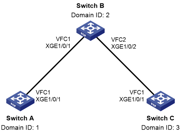
Procedure
|
|
IMPORTANT: By default, interfaces on the device are disabled (in ADM or Administratively Down state). To have an interface operate, you must use the undo shutdown command to enable that interface. |
This section describes only the FC routing configuration.
1. Configure Switch A:
# Configure the switch to operate in advanced mode, save the configuration, and reboot the switch. (Skip this step if the switch is operating in advanced mode.)
<SwitchA> system-view
[SwitchA] system-working-mode advance
[SwitchA] save
[SwitchA] quit
<SwitchA> reboot
# Configure the switch to operate in FCF mode.
<SwitchA> system-view
[SwitchA] fcoe-mode fcf
# Enable the fabric configuration feature for VSAN 1.
[SwitchA] vsan 1
[SwitchA-vsan1] domain configure enable
# Set the domain ID to 1.
[SwitchA-vsan1] domain-id 1 static
Nondisruptive reconfiguration might be performed or the switch might be isolated. Continue? [Y/N]:y
[SwitchA-vsan1] quit
# Create VFC 1.
[SwitchA] interface vfc 1
# Configure the mode of VFC 1 as E.
[SwitchA-Vfc1] fc mode e
# Bind VFC 1 to FortyGigE 1/0/1.
[SwitchA-Vfc1] bind interface fortygige 1/0/1
# Assign VFC 1 to VSAN 1 as a trunk port.
[SwitchA-Vfc1] port trunk vsan 1
[SwitchA-Vfc1] quit
# Configure FortyGigE 1/0/1 as a trunk port, and assign the port to VLAN 10.
[SwitchA] interface fortygige 1/0/1
[SwitchA-FortyGigE1/0/1] port link-type trunk
[SwitchA-FortyGigE1/0/1] port trunk permit vlan 10
[SwitchA-FortyGigE1/0/1] quit
# Enable FC and FCoE in VLAN 10 and map VLAN 10 to VSAN 1.
[SwitchA] vlan 10
[SwitchA-vlan10] fcoe enable vsan 1
[SwitchA-vlan10] quit
# Configure two static routes in VSAN 1.
[SwitchA] vsan 1
[SwitchA-vsan1] fc route-static 020000 8 vfc 1
[SwitchA-vsan1] fc route-static 030000 8 vfc 1
2. Configure Switch B:
# Configure the switch to operate in advanced mode, save the configuration, and reboot the switch. (Skip this step if the switch is operating in advanced mode.)
<SwitchB> system-view
[SwitchB] system-working-mode advance
[SwitchB] save
[SwitchB] quit
<SwitchB> reboot
# Configure the switch to operate in FCF mode.
<SwitchB> system-view
[SwitchB] fcoe-mode fcf
# Enable the fabric configuration feature for VSAN 1.
[SwitchB] vsan 1
[SwitchB-vsan1] domain configure enable
# Set the domain ID to 2.
[SwitchB-vsan1] domain-id 2 static
Nondisruptive reconfiguration might be performed or the switch might be isolated. Continue? [Y/N]:y
[SwitchB-vsan1] quit
# Create VFC 1.
[SwitchB] interface vfc 1
# Configure the mode of VFC 1 as E.
[SwitchB-Vfc1] fc mode e
# Bind VFC 1 to FortyGigE 1/0/1.
[SwitchB-Vfc1] bind interface fortygige 1/0/1
# Assign VFC 1 to VSAN 1 as a trunk port.
[SwitchB-Vfc1] port trunk vsan 1
[SwitchB-Vfc1] quit
# Configure FortyGigE 1/0/1 as a trunk port, and assign the port to VLAN 10.
[SwitchB] interface fortygige 1/0/1
[SwitchB-FortyGigE1/0/1] port link-type trunk
[SwitchB-FortyGigE1/0/1] port trunk permit vlan 10
[SwitchB-FortyGigE1/0/1] quit
# Create VFC 2.
[SwitchB] interface vfc 2
# Configure the mode of VFC 2 as E.
[SwitchB-Vfc2] fc mode e
# Bind VFC 2 to FortyGigE 1/0/2.
[SwitchB-Vfc2] bind interface fortygige 1/0/2
# Assign VFC 2 to VSAN 1 as a trunk port.
[SwitchB-Vfc2] port trunk vsan 1
[SwitchB-Vfc2] quit
# Configure FortyGigE 1/0/2 as a trunk port, and assign the port to VLAN 10.
[SwitchB] interface fortygige 1/0/2
[SwitchB-FortyGigE1/0/2] port link-type trunk
[SwitchB-FortyGigE1/0/2] port trunk permit vlan 10
[SwitchB-FortyGigE1/0/2] quit
# Enable FC and FCoE in VLAN 10 and map VLAN 10 to VSAN 1.
[SwitchB] vlan 10
[SwitchB-vlan10] fcoe enable vsan 1
[SwitchB-vlan10] quit
# Configure two static routes in VSAN 1.
[SwitchB] vsan 1
[SwitchB-vsan1] fc route-static 010000 8 vfc 1
[SwitchB-vsan1] fc route-static 030000 8 vfc 2
3. Configure Switch C:
# Configure the switch to operate in advanced mode, save the configuration, and reboot the switch. (Skip this step if the switch is operating in advanced mode.)
<SwitchC> system-view
[SwitchC] system-working-mode advance
[SwitchC] save
[SwitchC] quit
<SwitchC> reboot
# Configure the switch to operate in FCF mode.
<SwitchC> system-view
[SwitchC] fcoe-mode fcf
# Enable the fabric configuration feature for VSAN 1.
[SwitchC] vsan 1
[SwitchC-vsan1] domain configure enable
# Set the domain ID to 3.
[SwitchC-vsan1] domain-id 3 static
Nondisruptive reconfiguration might be performed or the switch might be isolated. Continue? [Y/N]:y
[SwitchC-vsan1] quit
# Create VFC 1.
[SwitchC] interface vfc 1
# Configure the mode of VFC 1 as E.
[SwitchC-Vfc1] fc mode e
# Bind VFC 1 to FortyGigE 1/0/1.
[SwitchC-Vfc1] bind interface fortygige 1/0/1
# Assign VFC 1 to VSAN 1 as a trunk port.
[SwitchC-Vfc1] port trunk vsan 1
[SwitchC-Vfc1] quit
# Configure FortyGigE 1/0/1 as a trunk port, and assign the port to VLAN 10.
[SwitchC] interface fortygige 1/0/1
[SwitchC-FortyGigE1/0/1] port link-type trunk
[SwitchC-FortyGigE1/0/1] port trunk permit vlan 10
[SwitchC-FortyGigE1/0/1] quit
# Enable FC and FCoE in VLAN 10 and map VLAN 10 to VSAN 1.
[SwitchC] vlan 10
[SwitchC-vlan10] fcoe enable vsan 1
[SwitchC-vlan10] quit
# Configure two static routes in VSAN 1.
[SwitchC] vsan 1
[SwitchC-vsan1] fc route-static 010000 8 vfc 1
[SwitchC-vsan1] fc route-static 020000 8 vfc 1
Verifying the configuration
# Display the FC routing table in VSAN 1 on Switch A.
[SwitchA-vsan1] display fc routing-table vsan 1
Routing Table: VSAN 1
Destinations : 6 Routes : 6
Destination/mask Protocol Preference Cost Interface
0x020000/8 STATIC 10 0 Vfc1
0x030000/8 STATIC 10 0 Vfc1
0xfffc01/24 DIRECT 0 0 InLoop0
0xfffffa/24 DIRECT 0 0 InLoop0
0xfffffc/24 DIRECT 0 0 InLoop0
0xfffffd/24 DIRECT 0 0 InLoop0
# Display the FC routing table in VSAN 1 on Switch B.
[SwitchB-vsan1] display fc routing-table vsan 1
Routing Table: VSAN 1
Destinations : 6 Routes : 6
Destination/mask Protocol Preference Cost Interface
0x010000/8 STATIC 10 0 Vfc1
0x030000/8 STATIC 10 0 Vfc2
0xfffc02/24 DIRECT 0 0 InLoop0
0xfffffa/24 DIRECT 0 0 InLoop0
0xfffffc/24 DIRECT 0 0 InLoop0
0xfffffd/24 DIRECT 0 0 InLoop0
# Display the FC routing table in VSAN 1 on Switch C.
[SwitchC-vsan1] display fc routing-table vsan 1
Routing Table: VSAN 1
Destinations : 6 Routes : 6
Destination/mask Protocol Preference Cost Interface
0x010000/8 STATIC 10 0 Vfc1
0x020000/8 STATIC 10 0 Vfc1
0xfffc03/24 DIRECT 0 0 InLoop0
0xfffffa/24 DIRECT 0 0 InLoop0
0xfffffc/24 DIRECT 0 0 InLoop0
0xfffffd/24 DIRECT 0 0 InLoop0
# FCping Switch C from Switch A.
[SwitchA-vsan1] fcping fcid fffc03 vsan 1
FCPING fcid 0xfffc03: 128 data bytes, press CTRL+C to break
Reply from 0xfffc03: bytes = 128 time = 23 ms
Reply from 0xfffc03: bytes = 128 time = 9 ms
Reply from 0xfffc03: bytes = 128 time = 19 ms
Reply from 0xfffc03: bytes = 128 time = 14 ms
Reply from 0xfffc03: bytes = 128 time = 25 ms
--- 0xfffc03 fcping statistics ---
5 packet(s) transmitted
5 packet(s) received
0.00% packet loss
round-trip min/avg/max = 9/18/25 ms
The output shows that Switch A can reach Switch C.
Example: Configuring FSPF by using FC interfaces
Network configuration
As shown in Figure 29, configure FSPF to enable the two FCF switches to communicate with each other.

Procedure
|
|
IMPORTANT: By default, interfaces on the device are disabled (in ADM or Administratively Down state). To have an interface operate, you must use the undo shutdown command to enable that interface. |
This section describes only FC routing configurations.
1. Configure Switch A:
# Configure the switch to operate in advanced mode, save the configuration, and reboot the switch. (Skip this step if the switch is operating in advanced mode.)
<SwitchA> system-view
[SwitchA] system-working-mode advance
[SwitchA] save
[SwitchA] quit
<SwitchA> reboot
# Configure the switch to operate in FCF mode.
<SwitchA> system-view
[SwitchA] fcoe-mode fcf
# Enable the fabric configuration feature for VSAN 1.
[SwitchA] vsan 1
[SwitchA-vsan1] domain configure enable
# Set the domain ID to 1.
[SwitchA-vsan1] domain-id 1 static
Nondisruptive reconfiguration might be performed or the switch might be isolated. Continue? [Y/N]:y
# Enable FSPF.
[SwitchA-vsan1] fspf enable
[SwitchA-vsan1] quit
# Change FortyGigE 1/0/1 into FC 1/0/1.
[SwitchA] interface fortygige 1/0/1
[SwitchA-FortyGigE1/0/1] port-type fc
# Configure the mode of FC 1/0/1 as E.
[SwitchA-Fc1/0/1] fc mode e
# Configure FC 1/0/1 to autonegotiate the speed.
[SwitchA-Fc1/0/1] speed auto
# Configure the trunk mode of FC 1/0/1 as On, and assign FC 1/0/1 to VSAN 1 as a trunk port.
[SwitchA-Fc1/0/1] port trunk mode on
[SwitchA-Fc1/0/1] port trunk vsan 1
# Enable FSPF on FC 1/0/1.
[SwitchA-Fc1/0/1] undo fspf silent vsan 1
[SwitchA-Fc1/0/1] quit
# Enable FC and FCoE in VLAN 10 and map VLAN 10 to VSAN 1.
[SwitchA] vlan 10
[SwitchA-vlan10] fcoe enable vsan 1
[SwitchA-vlan10] quit
2. Configure Switch B:
# Configure the switch to operate in advanced mode, save the configuration, and reboot the switch. (Skip this step if the switch is operating in advanced mode.)
<SwitchB> system-view
[SwitchB] system-working-mode advance
[SwitchB] save
[SwitchB] quit
<SwitchB> reboot
# Configure the switch to operate in FCF mode.
<SwitchB> system-view
[SwitchB] fcoe-mode fcf
# Enable the fabric configuration feature for VSAN 1.
[SwitchB] vsan 1
[SwitchB-vsan1] domain configure enable
# Set the domain ID to 2.
[SwitchB-vsan1] domain-id 2 static
Nondisruptive reconfiguration might be performed or the switch might be isolated. Continue? [Y/N]:y
# Enable FSPF.
[SwitchB-vsan1] fspf enable
[SwitchB-vsan1] quit
# Change FortyGigE 1/0/1 into FC 1/0/1.
[SwitchB] interface fortygige 1/0/1
[SwitchB-FortyGigE1/0/1] port-type fc
# Configure the mode of FC 1/0/1 as E.
[SwitchB-Fc1/0/1] fc mode e
# Configure FC 1/0/1 to autonegotiate the speed.
[SwitchB-Fc1/0/1] speed auto
# Configure the trunk mode of FC 1/0/1 as On, and assign FC 1/0/1 to VSAN 1 as a trunk port.
[SwitchB-Fc1/0/1] port trunk mode on
[SwitchB-Fc1/0/1] port trunk vsan 1
# Enable FSPF for FC 1/0/1.
[SwitchB-Fc1/0/1] undo fspf silent vsan 1
[SwitchB-Fc1/0/1] quit
# Enable FC and FCoE in VLAN 10 and map VLAN 10 to VSAN 1.
[SwitchB] vlan 10
[SwitchB-vlan10] fcoe enable vsan 1
[SwitchB-vlan10] quit
Verifying the configuration
# Display FSPF neighbor information on Switch A.
[SwitchA] display fspf neighbor
FSPF neighbor information of VSAN 1(01):
Interface NbrDomain IfIndex NbrIfIndex Dead Time State
Fc1/0/1 2 0x68 0x68 00:01:06 Full
# Display information about the FC routing table on Switch A.
[SwitchA] display fc routing-table vsan 1
Routing Table: VSAN 1
Destinations : 5 Routes : 5
Destination/mask Protocol Preference Cost Interface
0x020000/8 FSPF 20 1062 Fc1/0/1
0xfffc01/24 DIRECT 0 0 InLoop0
0xfffffa/24 DIRECT 0 0 InLoop0
0xfffffc/24 DIRECT 0 0 InLoop0
0xfffffd/24 DIRECT 0 0 InLoop0
# FCping Switch B from Switch A.
[SwitchA] fcping fcid fffc02 vsan 1
FCPING fcid 0xfffc02: 128 data bytes, press CTRL+C to break.
Reply from 0xfffc02: bytes = 128 time = 1.102 ms
Reply from 0xfffc02: bytes = 128 time = 0.276 ms
Reply from 0xfffc02: bytes = 128 time = 0.253 ms
Reply from 0xfffc02: bytes = 128 time = 0.270 ms
Reply from 0xfffc02: bytes = 128 time = 0.247 ms
--- 0xfffc02 fcping statistics ---
5 packet(s) transmitted
5 packet(s) received
0.00% packet loss
round-trip min/avg/max = 0.247/0.430/1.102 ms
The output shows that Switch A can reach Switch B.
Example: Configuring FSPF by using VFC interfaces
Network configuration
As shown in Figure 30, configure FSPF so the two FCF switches can communicate with each other.

Procedure
|
|
IMPORTANT: By default, interfaces on the device are disabled (in ADM or Administratively Down state). To have an interface operate, you must use the undo shutdown command to enable that interface. |
This section describes only the FC routing configurations.
1. Configure Switch A:
# Configure the switch to operate in advanced mode, save the configuration, and reboot the switch. (Skip this step if the switch is operating in advanced mode.)
<SwitchA> system-view
[SwitchA] system-working-mode advance
[SwitchA] save
[SwitchA] quit
<SwitchA> reboot
# Configure the switch to operate in FCF mode.
<SwitchA> system-view
[SwitchA] fcoe-mode fcf
# Create VSAN 2 and enable the fabric configuration feature for VSAN 2.
[SwitchA] vsan 2
[SwitchA-vsan2] domain configure enable
# Set the domain ID to 1.
[SwitchA-vsan2] domain-id 1 static
Nondisruptive reconfiguration might be performed or the switch might be isolated. Continue? [Y/N]:y
# Enable FSPF.
[SwitchA-vsan2] fspf enable
[SwitchA-vsan2] quit
# Create VFC 1.
[SwitchA] interface vfc 1
# Configure the mode of VFC 1 as E.
[SwitchA-Vfc1] fc mode e
# Bind VFC 1 to FortyGigE 1/0/1.
[SwitchA-Vfc1] bind interface fortygige 1/0/1
# Assign VFC 1 to VSAN 2 as a trunk port.
[SwitchA-Vfc1] port trunk vsan 2
[SwitchA-Vfc1] quit
# Configure FortyGigE 1/0/1 as a trunk port, and assign the port to VLAN 10.
[SwitchA] interface fortygige 1/0/1
[SwitchA-FortyGigE1/0/1] port link-type trunk
[SwitchA-FortyGigE1/0/1] port trunk permit vlan 10
[SwitchA-FortyGigE1/0/1] quit
# Enable FC and FCoE in VLAN 10 and map VLAN 10 to VSAN 2.
[SwitchA] vlan 10
[SwitchA-vlan10] fcoe enable vsan 2
[SwitchA-vlan10] quit
# Enable FSPF for VFC 1.
[SwitchA] interface vfc 1
[SwitchA-Vfc1] undo fspf silent vsan 2
[SwitchA-Vfc1] quit
2. Configure Switch B:
# Configure the switch to operate in advanced mode, save the configuration, and reboot the switch. (Skip this step if the switch is operating in advanced mode.)
<SwitchB> system-view
[SwitchB] system-working-mode advance
[SwitchB] save
[SwitchB] quit
<SwitchB> reboot
# Configure the switch to operate in FCF mode.
<SwitchB> system-view
[SwitchB] fcoe-mode fcf
# Create VSAN 2 and enable the fabric configuration feature for VSAN 2.
[SwitchB] vsan 2
[SwitchB-vsan2] domain configure enable
# Set the domain ID to 2.
[SwitchB-vsan2] domain-id 2 static
Nondisruptive reconfiguration might be performed or the switch might be isolated. Continue? [Y/N]:y
# Enable FSPF.
[SwitchB-vsan2] fspf enable
[SwitchB-vsan2] quit
# Create VFC 1.
[SwitchB] interface vfc 1
# Configure the mode of VFC 1 as E.
[SwitchB-Vfc1] fc mode e
# Bind VFC 1 to FortyGigE 1/0/1.
[SwitchB-Vfc1] bind interface fortygige 1/0/1
# Assign VFC 1 to VSAN 2 as a trunk port.
[SwitchB-Vfc1] port trunk vsan 2
[SwitchB-Vfc1] quit
# Configure FortyGigE 1/0/1 as a trunk port, and assign the port to VLAN 10.
[SwitchB] interface fortygige 1/0/1
[SwitchB-FortyGigE1/0/1] port link-type trunk
[SwitchB-FortyGigE1/0/1] port trunk permit vlan 10
[SwitchB-FortyGigE1/0/1] quit
# Enable FC and FCoE in VLAN 10 and map VLAN 10 to VSAN 2.
[SwitchB] vlan 10
[SwitchB-vlan10] fcoe enable vsan 2
[SwitchB-vlan10] quit
# Enable FSPF for VFC 1.
[SwitchB] interface vfc 1
[SwitchB-Vfc1] undo fspf silent vsan 2
[SwitchB-Vfc1] quit
Verifying the configuration
# Display the FSPF neighbor information for Switch A.
[SwitchA] display fspf neighbor
FSPF neighbor information of VSAN 2(01):
Interface NbrDomain IfIndex NbrIfIndex Dead Time State
Vfc1 2 0x68 0x68 00:01:06 Full
# Display the routing table information for Switch A.
[SwitchA] display fc routing-table vsan 2
Routing Table: VSAN 2
Destinations : 5 Routes : 5
Destination/mask Protocol Preference Cost Interface
0x020000/8 FSPF 20 100 Vfc1
0xfffc01/24 DIRECT 0 0 InLoop0
0xfffffa/24 DIRECT 0 0 InLoop0
0xfffffc/24 DIRECT 0 0 InLoop0
0xfffffd/24 DIRECT 0 0 InLoop0
# FCping Switch B from Switch A.
[SwitchA] fcping fcid fffc02 vsan 2
FCPING fcid 0xfffc02: 128 data bytes, press CTRL+C to break.
Reply from 0xfffc02: bytes = 128 time = 1.102 ms
Reply from 0xfffc02: bytes = 128 time = 0.276 ms
Reply from 0xfffc02: bytes = 128 time = 0.253 ms
Reply from 0xfffc02: bytes = 128 time = 0.270 ms
Reply from 0xfffc02: bytes = 128 time = 0.247 ms
--- 0xfffc02 fcping statistics ---
5 packet(s) transmitted
5 packet(s) received
0.00% packet loss
round-trip min/avg/max = 0.247/0.430/1.102 ms
The output shows that Switch A can reach Switch B.
Configuring FC zones
About FC zones
N_Ports in the same VSAN can access one another only if these N_Ports register name services. This creates data security risks.
Zoning can solve the security problem by dividing a VSAN into zones and adding N_Ports or F_Ports to different zones for different purposes. In this way, N_Ports in different zones are separated to implement access control.
Zoning mode
Two zoning modes are available: basic zoning and enhanced zoning.
Table 5 shows the differences between the two zoning modes.
Table 5 Differences between basic zoning and enhanced zoning
|
Basic zoning |
Enhanced zoning |
|
The default zone policy and hard zoning status are not distributed during the zone distribution process. You must manually configure these settings on all switches to ensure consistency across the fabric. |
The default zone policy and hard zoning status are distributed throughout the fabric. |
|
If a zone belongs to multiple zone sets, an instance of the zone is created in each zone set. |
Zone sets can reference a defined zone, which reduces the payload of packets for zone merge or distribution. |
|
Merge rules are simple. |
Merge rules are complex and are affected by the merge control feature. |
Zone database
To control access among N_Ports, you can assign N_Ports to different zones as needed, which form a zone set. The same N_Ports can form multiple zone sets according to different zone division policies. These zones and zone sets form a zone database.
Zone database structure
The zone database is organized into three levels, including zone set, zone, and zone member.
Figure 31 Zone database structure
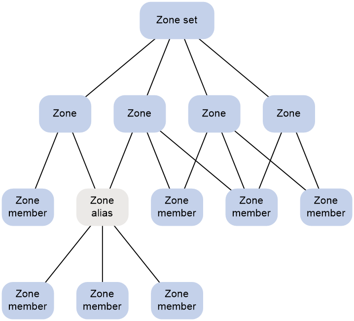
In the zone database structure:
· A zone set is a set of zones. A zone is a set of zone members, which are N_Ports or F_Ports.
¡ N_Port membership can be identified by the WWN (pWWN) or FC address of an N_Port.
¡ F_Port membership is identified by the WWN of an F_Port (fWWN).
· Each VSAN can have multiple zone sets, each zone set can have multiple zones, and each zone can have multiple zone members.
· Zone membership configuration supports use of zone aliases. A zone alias is a set of N_Ports, which can be considered as a whole. To simplify configuration, you can add common zone members in multiple zones to a zone alias, and use the zone alias in different zones.
Active zone set
Each VSAN can have multiple zone sets, but only one zone set can be effective at a time. It is called the active zone set. Access control over N_Ports is subject to the active zone set.
To ensure consistent access control over N_Ports across a fabric, specify a zone set as the active zone set on a switch and distribute it to the entire fabric.
When you activate a zone set, a copy of the zone set at the time of activation is created and is called the active zone set. After that, modifications to the zone set do not take effect on the copy until the zone set is reactivated. Figure 32 shows the relationship between active and full zone sets.
Figure 32 Active and full zone sets
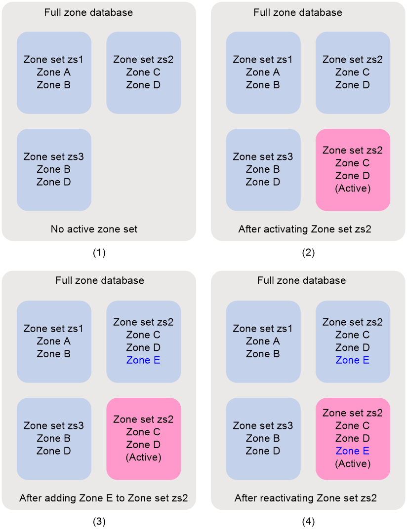
In basic zoning mode, the system checks the size of the data to be distributed when you activate a zone set. If the size of the data exceeds the system limit, the activation fails, and an error message is displayed.
In enhanced zoning mode, the system does not limit the size of the data to be distributed.
Default zone
Registered N_Ports that are not in the active zone set automatically become part of the default zone. The N_Ports in zones of the active zone set are part of the active zone set.
If members of the default zone are allowed to access each other, the following events occur:
· The default zone can be considered to be part of the active zone set.
· The default zone participates in access control among N_Ports.
Otherwise, the default zone is not in the active zone set and does not participate in access control among the N_Ports.
In basic zoning mode, the switch does not distribute the default zone policy across the fabric. You must manually configure a consistent default zone policy across the fabric. In enhanced zoning mode, the switch distributes the default zone policy during the zone distribution process.
Peer zone
A zone can be a peer zone or a common zone. Unless otherwise indicated, a zone in FC and FCoE refers to a common zone.
Peer zones are supported only in enhanced zoning mode.
You can define a peer zone on a target device by specifying a zone name, the principal member, and peer members. The switch automatically creates the defined peer zone when receiving related packets from the target device.
Each peer zone can have one principal member and multiple peer members. The principal member can communicate with all peer members. Any two peer members in a peer zone cannot communicate with each other unless they are allowed to communicate with each other in another zone.
Pairwise
The Pairwise feature is supported only in enhanced zoning mode.
Typically, servers do not need to access each other, and storage devices do not need to access each other. Without the Pairwise feature, an access entry is generated for any pair of members in a zone.
The following roles are defined for zone members:
· Initiator—Typically a server.
· Target—Typically a storage device.
You can specify the role of a member as an initiator, a target, or both when adding the member. A member can have different roles in different zones.
The Pairwise feature runs on a per-zone basis. When the Pairwise feature is enabled for a zone, access entries are not generated for initiator-initiator pairs or target-target pairs.
· An initiator member can access target members.
· A target member can access initiator members.
· A member acting as both an initiator and a target can access both target members and initiator members.
When the Pairwise feature is disabled for a zone, member roles do not take effect in that zone.
Zone distribution in basic zoning mode
Zone distribution occurs when a switch distributes its zone database to all the other devices in the same fabric. The distributing switch is called a manager switch, and all other switches are called managed switches.
In basic zoning mode, the following distribution types are provided:
· Complete distribution—Distributes both the active zone set and the zone database.
· Incomplete distribution—Distributes only the active zone set.
Zone distribution methods
You can distribute zones by using one of the following methods:
· Activate a zone set as the active zone set on a switch by using the zoneset activate command. At the time of activation, the active zone set is distributed to all the other switches.
If the size of the zone set exceeds the system limit, the activation fails.
This method determines whether to carry the zone database according to the configured distribution type.
· Distribute the active zone set and the zone database directly by using the zoneset distribute command on a switch.
This method performs a complete distribution regardless of the configured distribution type.
Managed switches replace their respective active zone sets or zone databases with the received data, regardless of the distribution types configured on them. If a managed switch receives only the zone database, the managed switch does not retain its active zone set (if present) after replacement.
Zone distribution process
The manager switch completes data synchronization with each managed switch by using the following packets:
· Acquire Change Authorization (ACA).
· Stage Fabric Configuration Update (SFC).
· Update Fabric Configuration (UFC).
· Release Change Authorization (RCA).
These types of packets implement locking, data synchronization, submission, and unlocking processes, respectively. These processes ensure that only one switch is the manager switch when multiple users trigger a data distribution on different switches at the same time.
Figure 33 Distribution process

The distribution process is as follows:
1. The manager switch obtains the status of each managed switch through an ACA request. After sending the ACA request, the manager switch enters the locked state.
The ACA request carries the fabric-wide list of domain IDs (addresses of all switches in the fabric) known to the manager switch.
2. After receiving the ACA request, a managed switch compares its list of domain IDs with that in the packet.
¡ If they are consistent, the fabric is stable. In this case, the managed switch is prepared for synchronization, replies with an ACC (acknowledgment) packet, and enters the change authorization (locked) state.
|
|
IMPORTANT: For a fabric to be stable, make sure the routes are correctly and consistently configured, and no unreachable routes exist. |
¡ If the managed switch has been in change authorization state or cannot process the ACA request, it replies with an RJT (reject) packet.
3. The manager switch starts data synchronization by sending an SFC request only after receiving ACC requests from all managed switches. Otherwise, it notifies managed switches to release the change authorization state by sending an RCA request.
If the managed switch replies with neither an ACC packet nor an RJT packet because of its abnormal state, the manager switch cannot release its locked state. To prevent this situation, the manager switch transmits an ACA request up to three times.
¡ If no reply is received, the manager switch releases its locked state.
¡ If the manager switch becomes abnormal after sending an ACA request, the managed switch will be in locked state and cannot receive subsequent packets. In this situation, the managed switch releases its locked state after waiting for a period of time.
4. The manager switch sends an SFC request to all managed switches. The SFC request carries data to be synchronized, including the active zone set and zone database information. After receiving the SFC request, the managed switch calculates the total numbers of zones, zone sets, and zone aliases if its local zone database is replaced.
¡ If none of the total numbers exceed the limit, the managed switch replies with an ACC packet.
¡ If any of the total numbers exceed the limit, the managed switch replies with an RJT packet.
5. After receiving ACC packets from all managed switches, the manager switch sends a UFC request to the managed switches. The UFC request notifies the managed switches to replace their local data with the received data.
Otherwise, the manager switch sends an RCA request to notify managed switches to release the change authorization state.
6. After receiving the UFC request, the managed switch updates its local zone database. It replies with an ACC packet for a successful update and with an RJT packet for a failed update.
7. The manager switch notifies managed switches by sending an RCA request to release the change authorization state after receiving ACC packets from all managed switches.
8. After receiving the RCA request, the managed switch releases its change authorization state and replies with an ACC packet.
9. The manager switch releases its change authorization state after receiving ACC packets from all managed switches.
Zone distribution in enhanced zoning mode
Enhanced zoning has the following differences from basic zoning in zone distribution:
· Enhanced zoning distributes the zone policy and hard zoning status in addition to the active zone set and zone database.
The zone policy includes the merge control mode and default zone policy. For information about the merge control mode, see "Zone merge in enhanced zoning mode."
· Enhanced zoning always performs complete distribution and does not support the zoneset distribute full command.
You can use the same zone distribution methods for basic zoning as used in enhanced zoning mode.
A zoning mode switchover between basic zoning and enhanced zoning also causes zone distribution. Switchover-triggered distribution distributes the active zone set, zone database, zone policy, and hard zoning status.
For both switchover-triggered distribution and zone distribution in enhanced zoning mode, the SFC request includes the zone policy whether or not the SFC request has the active zone set and zone database.
For zone distribution in enhanced zoning mode, the SFC request always has hard zoning status.
For zone distribution caused by a switchover from basic zoning to enhanced zoning, the SFC request has hard zoning status.
For zone distribution caused by a switchover from enhanced zoning to basic zoning, the SFC request does not have hard zoning status.
Zone merge in basic zoning mode
When two fabrics are merged, zone data might exist in both fabrics. In this case, zone data needs to be merged. Zone data to be merged includes the active zone set and zone database.
In basic zoning mode, the following merge types are provided:
· Complete merge—Merges both the active zone sets and zone databases.
· Incomplete merge—Merges only the active zone sets.
The merged switches merge all received data, regardless of their merge types.
|
|
NOTE: The pWWN is a preferred choice over FC addresses to identify zone members, because FC addresses might change at fabric merge and the merge result might not be as expected. |
Zone merge process
When a switch discovers a new neighbor (the link layer module discovers neighbors and notifies the zone module), it starts a merge process with the neighbor. If the data changes after merging, the switch sends the changed data to neighbor switches until all switches in the fabric update their data.
During the merge, the switch sends Merge Request Resource Allocation (MRRA) requests to negotiate the size of data transmitted. Then, the switch sends Merge Request (MR) packets containing data to be merged to neighbor switches.
Figure 34 Zone merge process between two switches
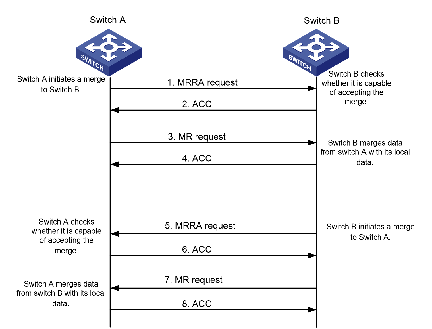
Switch A and Switch B are new neighbors to each other. Suppose that Switch A first initiates a merge to Switch B.
The zone merge process is as follows:
1. Switch A sends an MRRA request carrying the size of its data to be merged to Switch B.
2. After receiving the MRRA request, Switch B determines whether to accept the merge according to its local data size.
¡ If the size of the data to be merged is acceptable, it replies with an ACC packet.
¡ If the size of the data to be merged is not acceptable, it replies with an RJT packet.
3. After receiving the ACC packet, Switch A sends an MR request containing its zone data to Switch B.
4. After receiving the MR request, Switch B obtains the zone data and merges it with its local zone data.
5. Switch B replies with an ACC packet for a successful merge or with an RJT packet containing the cause of failure for a failed merge.
6. After the merge process initiated by Switch A is complete, the following rules apply:
¡ If the local data of Switch B is the same as or a subset of the local data of Switch A, Switch B ends the merge process with Switch A.
¡ Otherwise, Switch B initiates a merge process with Switch A.
The merge process is the same as the process initiated by Switch A to Switch B, as shown in steps 5, 6, 7, and 8 in Figure 34.
7. After the merge process initiated by Switch A is complete, Switch B initiates a merge process to all its neighbors. This synchronizes Switch B's local database changes resulting from the merge to the entire fabric.
Two 1-way merge processes can ensure data consistency between Switch A and Switch B.
|
|
NOTE: Consistent active zone sets among switches can be achieved by a merge. Consistent zone databases achieved after a merge, however, require all participating switches to be configured with complete merge. |
Zone merge rules
Table 6 Zone merge rules
|
Local database |
Neighbor database |
Merge status |
Merge result |
|
The zone databases contain zone sets with the same name, but zones in these zone sets have different names. |
Successful |
The union of the local database and neighbor database. Zone sets with the same name are merged. |
|
|
The zone databases contain zone sets with different names. |
Successful |
The union of the local database and neighbor database. All zone sets with different names are retained. |
|
|
The zone databases contain zones or zone aliases with different names. |
Successful |
The union of the local database and neighbor database. All zone sets or zone aliases with different names are retained. |
|
|
The Pairwise feature status is different for one or more of the zones with the same name in the active zone sets or zone databases. |
Failed |
Both databases remain unchanged. |
|
|
The databases contain zones or zone aliases with the same name but with one or more different zone members. |
Failed |
Both databases remain unchanged. |
|
|
Zones with the same name in the active zone set contain the same zone members, but one or more of these members have different roles. Or Zones or zone aliases with the same name in the zone databases contain the same zone members, but one or more of these members have different roles. |
Failed |
Both databases remain unchanged. |
|
|
Empty |
Contain data |
Successful |
The neighbor database overwrites the local database. |
|
Contain data |
Empty |
Successful |
The local database overwrites the neighbor database. |
|
|
NOTE: · If two active zone sets have different names, the larger name obtained by string comparison acts as the name of the active zone set after merging. · If the active zone sets on two switches fail to merge, the two switches isolate their connecting link by bringing down the relevant ports in the VSAN, in addition to keeping their zone databases unchanged. |
Zone merge in enhanced zoning mode
Merge differences between enhanced zoning and basic zoning
Enhanced zoning has the following differences from basic zoning in zone merge:
· Enhanced zoning always performs complete merges, regardless of the merge type.
· The MR request has the hard zoning status and a merge flag field in addition to the active zone set and zone database.
The merge flag field includes the merge control mode and default zone policy.
· In the event of a merge failure, the link between participating switches is isolated, and both zone databases remain unchanged.
· Enhanced zoning has stricter rules than basic zoning.
Merge rules for enhanced zoning
The enhanced zoning mode includes the following merge rules:
· If either the merge control mode or default zone policy is different from that in the local zone database, the merge will fail.
· If both the merge control mode and default zone policy are the same as that in the local zone database, the following rules apply:
¡ If the merge control mode is Restrict, the system checks whether the data carried in the MR request is the same as the local zone database.
- If the data is the same as the local zone database, the merge will succeed, and both databases remain unchanged.
- If the data is different from the local zone database, the merge will fail.
¡ If the merge control mode is Allow, the following rules apply:
- If the two active zone sets contain zones with the same name but with one or more different zone members, the merge will fail.
- If the two zone databases contain zone sets, zones, or zone aliases with the same name but one or more different members, the merge will fail.
- If the two zone databases contain zone members with the same name but one or more of these members have different roles, the merge will fail.
- If the two zone databases contain zones with the same name, but the Pairwise feature status is different for one or more of these zones, the merge will fail.
- If hard zoning status is different in the two zone databases, the merge will fail.
- If the two active zone sets contain zones with different names and none of the preceding conditions exist, the merge will succeed. The merged active zone set is the union of the two active zone sets.
- If the two zone databases contain zone sets, zones, or zone aliases with different names and none of the preceding conditions exist, the merge will succeed. The merged zone database is the union of the two zone databases.
Access control
For a server to access a disk device through the name service, the server and the disk device must be in one zone of the active zone set. Only members in the same zone can access each other.
Restrictions and guidelines: FC zone configuration
You cannot modify zone configurations during zone distribution or merge.
In a fabric, only one manager switch can initiate distribution at a time. The next distribution can be initiated only after the previous one is complete.
FC zone tasks at a glance
To configure FC zones, perform the following tasks:
2. Configure a zone alias, zone, peer zone, or zone set
a. (Optional.) Configuring a zone alias
c. (Optional.) Configuring a peer zone
3. Enabling the Pairwise feature
This feature is available only in enhanced zoning mode.
4. Configuring the default zone policy
5. Configuring the zone distribution and merge type
This task can be configured only in basic zoning mode.
6. Configuring the merge control mode
This task can be configured only in enhanced zoning mode.
7. (Optional.) Enabling hard zoning
8. Activating a zone set and distributing it to the entire fabric
9. (Optional.) Triggering a complete distribution
10. (Optional.) Rename or copy a zone alias, zone, or zone set
¡ Renaming a zone alias, zone, or zone set
¡ Copying a zone alias, zone, or zone set
11. (Optional.) Deleting the zone database
12. (Optional.) Enabling SNMP notifications for the zone module
Configuring a zoning mode
About this task
Two zoning modes are available: basic zoning and enhanced zoning. By default, the basic zoning mode is enabled.
A zoning mode switchover causes a zone distribution to ensure zoning mode consistency across the fabric.
When you switch between zoning modes, the system prints a message that the switchover will cause a zone distribution.
· If you enter No, no operation is performed.
· If you enter Yes, the local switch changes the zoning mode and generates the corresponding configuration. Then, the local switch distributes the change to the entire fabric.
Restrictions and guidelines
You can switch from basic zoning to enhanced zoning only if the following conditions are met:
· All switches in the fabric support the enhanced zoning mode.
· No invalid static routes exist in the fabric.
After enhanced zoning is enabled on a switch, the switch checks ESS negotiation results for enhanced zoning support on other switches.
The switch performs ESS negotiation with all switches that appear in its routing table as destinations, including unreachable destinations in invalid static routes. The switch assumes that unreachable destinations do not support enhanced zoning.
If the distribution fails, the system prints a log message, and the change takes effect on the local switch. In this case, manually trigger a complete distribution to ensure zoning mode consistency across the fabric.
For a switchover from enhanced zoning to basic zoning, if the size of the active zone set exceeds the system limit in basic zoning mode, the switchover fails.
Procedure
1. Enter system view.
system-view
2. Enter VSAN view.
vsan vsan-id
3. Configure a zoning mode.
¡ Enable the enhanced zoning mode:
zone mode enhanced
¡ Enable the basic zoning mode:
undo zone mode enhanced
By default, the basic zoning mode is enabled.
Configuring a zone alias
About this task
You can specify members of a zone alias by using their FC addresses, pWWNs, or fWWNs. An fWWN is the WWN of an F_Port. An F_Port member represents all N_Ports that log in through the F_Port. Any specified N_Port members can be indirectly connected to the switch.
Restrictions and guidelines
You can specify the role of a member as an initiator, a target, or both when adding the member. The role can be configured only in enhanced zoning mode and takes effect only when the Pairwise feature is enabled.
Procedure
1. Enter system view.
system-view
2. Enter VSAN view.
vsan vsan-id
3. Create a zone alias and enter zone alias view.
zone-alias name zone-alias-name
4. Add a member to the zone alias.
member { fcid fcid | fwwn fwwn | pwwn pwwn } [ initiator | target ]
By default, no member exists in a new zone alias.
Configuring a zone
About this task
You can specify members of a zone by using their FC addresses, pWWNs, fWWNs, or zone aliases. An fWWN is the WWN of an F_Port. An F_Port member represents all N_Ports that log in through the F_Port. A zone alias represents a group of N_Ports. Any specified N_Port members can be indirectly connected to the switch. A member can belong to more than one zone.
Restrictions and guidelines
You can specify the role of a member as an initiator, a target, or both when adding the member. The role can be configured only in enhanced zoning mode and takes effect only when the Pairwise feature is enabled.
As a best practice, add one server HBA and one storage HBA to a zone. If a zone has one server HBA and multiple storage HBAs, you must enable the Pairwise feature for the zone.
Procedure
1. Enter system view.
system-view
2. Enter VSAN view.
vsan vsan-id
3. Create a zone and enter zone view.
zone name zone-name
4. Add a member to the zone.
member { { fcid fcid | fwwn fwwn | pwwn pwwn } [ initiator | target ] | zone-alias zone-alias-name }
By default, no member exists in a new zone.
Configuring a peer zone
About this task
A peer zone can be automatically created by Smart SAN packets or manually configured.
Restrictions and guidelines
This feature allows you to convert a common zone to a peer zone. To convert a common zone to a peer zone, you must first enable Smart SAN for FC/FCoE.
A zone with the Pairwise feature enabled cannot be converted to a peer zone by using this feature.
Procedure
1. Enter system view.
system-view
2. Enter VSAN view.
vsan vsan-id
3. Enter zone view.
zone name zone-name
By default, a zone is a common zone.
4. Convert the common zone to a peer zone and specify the principal member for the peer zone.
zone-type peer-zone principal-member wwn
The principal member must be a port on a node.
This command specifies the principal member as a target.
This command deletes the settings for the common zone.
Configuring a zone set
1. Enter system view.
system-view
2. Enter VSAN view.
vsan vsan-id
3. Create a zone set and enter zone set view.
zoneset name zoneset-name
4. Add a zone to the zone set.
member zone-name
By default, no zone exists in a new zone set.
Enabling the Pairwise feature
About this task
This feature allows a zone member to access only members with a different role in the same zone. A member with both roles can access both initiator members and target members.
After you disable this feature for a zone, all members in the zone can access each other, regardless of member roles.
Restrictions and guidelines
This feature is available only in enhanced zoning mode.
Procedure
1. Enter system view.
system-view
2. Enter VSAN view.
vsan vsan-id
3. Enter zone view.
zone name zone-name
4. Enable the Pairwise feature.
pairwise-zoning enable
By default, the Pairwise feature is disabled.
Configuring the default zone policy
About this task
In enhanced zoning mode, the switch distributes the default zone policy with other zone data. In basic zoning mode, you must manually configure a consistent default zone policy across the fabric.
After the switch performs a zoning mode switchover, it also distributes the default zone policy with other zone data.
Procedure
1. Enter system view.
system-view
2. Enter VSAN view.
vsan vsan-id
3. Configuring the default zone policy.
¡ Permit members in the default zone to access each other.
zone default-zone permit
By default, default zone members are not permitted to access each other.
¡ Deny members in the default zone from accessing each other.
undo zone default-zone permit
By default, default zone members are not permitted to access each other.
Configuring the zone distribution and merge type
About this task
Complete distribution (or merge) distributes (or merges) both the active zone set and zone database. Incomplete distribution (or merge) distributes (or merges) only the active zone set.
Restrictions and guidelines
This feature is supported only in basic zoning mode. In enhanced zoning mode, the zone distribution and merge type is always complete, and this feature is not supported.
The configured distribution type applies to distribution operations triggered by the zoneset activate command instead of the zoneset distribute command.
The configured merge type applies to all merge operations.
Procedure
1. Enter system view.
system-view
2. Enter VSAN view.
vsan vsan-id
3. Configure the zone distribution and merge type as complete.
zoneset distribute full
The default setting is incomplete.
Configuring the merge control mode
About this task
Two merge control modes are available: Restrict and Allow. For information about these two modes, see "Zone merge in enhanced zoning mode."
This feature is supported only in enhanced zoning mode. The merge control mode affects the result of a merge operation. A merge operation can succeed only when the merge control mode is the same on both participating switches. If the merge operation fails, the link connecting the participating switches is isolated.
Restrictions and guidelines
To ensure a consistent merge control mode across the fabric, use the zone activate or zone distribute command after you configure a merge control mode.
Procedure
1. Enter system view.
system-view
2. Enter VSAN view.
vsan vsan-id
3. Configure the merge control mode as Restrict:
zone merge-control restrict
The default merge control mode is Allow.
Enabling hard zoning
About this task
Switches implement zone access control in one of the following methods:
· Soft zoning—When a registered node queries the nodes in the current fabric through generic service packets, soft zoning filters the nodes based on zone rules and returns only the matching nodes. Soft zoning is always in effect.
Because soft zoning is used only when a node accesses other nodes, it can restrict only the result of queries that a node initiates to switches, and it cannot directly control the underlayer traffic. When a node performs traffic attacks against the node that should be filtered by zone rules, soft zoning cannot perform access control for the node.
· Hard zoning—Hard zoning converts the zone configurations into lower-layer driver rules and deploys the rules to the hardware to form hardware zone rules. Then, the traffic in the switch is forwarded strictly based on hardware zone rules. Hard zoning takes effect only when the hardware resources are sufficient for deploying zone rules.
When the hardware resources are not sufficient for deploying the hardware zone rules of the current VSAN, the system performs the following operations:
¡ Clears all deployed hardware zone rules in order to keep the integrity of rules.
¡ Automatically disables hard zoning.
To improve the security for a VSAN, you can enable hard zoning for the VSAN. After hard zoning is enabled for a VSAN, the system triggers deploying all zone rules of the VSAN. After hard zoning is manually disabled for a VSAN, the system clears the hardware zone rules already deployed for the VSAN and stops deploying new zone rules for the VSAN.
The two methods can work separately and supplement each other. They work together to implement node access control based on the zone configurations.
Restrictions and guidelines
Do not configure the zone hard-zoning enable command when the switch is merging or distributing zones.
When soft zoning is enough for meeting the access control requirements of a VSAN, you can disable hard zoning for the VSAN to save the hardware entry resources.
In basic zoning mode, you must manually configure hard zoning to ensure consistency across the fabric. In enhanced zoning mode, zone distribution distributes hard zoning status with other zone data.
To view the hard zoning status, use the display zone status command.
Procedure
1. Enter system view.
system-view
2. Enter VSAN view.
vsan vsan-id
3. Enable hard zoning.
zone hard-zoning enable
By default, hard zoning is enabled.
4. (Optional.) Display the hard zoning status.
display zone status
Activating a zone set and distributing it to the entire fabric
About this task
You can use the zoneset activate command to activate a zone set on a switch and distribute the active zone set to the entire fabric. Then, the active zone set is used to implement access control. The modifications to the active zone set do not take effect until reactivation.
The zone set to be activated must have been created and must contain at least one N_Port member. Only one active zone set can exist in a VSAN. In basic zoning mode, if the size of the active zone set exceeds the system limit, the activation fails.
In basic zoning mode, the distribution type specified by using the zoneset distribute full command applies to distribution operations triggered by the zoneset activate command. In enhanced zoning mode, the zoneset distribute full command is not supported, and the distribution type is always complete.
Restrictions and guidelines
In either basic or enhanced zoning mode, the system prints a log message if the distribution fails because of a network fault. To ensure a consistent active zone set across the fabric, reactivate the zone set after the network fault is fixed.
Active zone set information does not contain the alias names of zone members. If a zone in the active zone set has members with a zone alias, the non-overlapping N_Port members in the zone alias are added to the zone. You can view the zone member changes by using the display zoneset active command.
Prerequisites
The zone set to be activated must have been created and must contain at least one N_Port member. Only one active zone set can exist in a VSAN. In basic zoning mode, if the size of the active zone set exceeds the system limit, the activation fails.
Procedure
1. Enter system view.
system-view
2. Enter VSAN view.
vsan vsan-id
3. Activate a zone set as the active zone set and distribute it to the entire fabric.
zoneset activate name zoneset-name
Triggering a complete distribution
About this task
Use the zoneset distribute command to trigger a one-time complete distribution, which distributes both the active zone set and zone database. In enhanced zoning mode, the zone policy and hard zoning status are also distributed.
After activating a zone set by using the zoneset activate command, you can modify the zone database configuration. The zoneset distribute command distributes the active zone set and the modified zone database to the entire fabric without changing the active zone set.
Restrictions and guidelines
If the distribution fails because of a network fault, the system prints a log message. To ensure zone data consistency across the fabric, trigger a new complete distribution after the network fault is fixed.
Procedure
1. Enter system view.
system-view
2. Enter VSAN view.
vsan vsan-id
3. Trigger a complete distribution.
zoneset distribute
Renaming a zone alias, zone, or zone set
1. Enter system view.
system-view
2. Enter VSAN view.
vsan vsan-id
3. Rename a zone alias.
zone-alias rename old-name new-name
The zone alias to be renamed must have been created, and the new zone alias must not have been created.
4. Rename a zone.
zone rename old-name new-name
The zone to be renamed must have been created, and the new zone must not have been created.
After renaming a peer zone on the switch, you must modify the peer zone name on nodes to the same name.
5. Rename a zone set.
zoneset rename old-name new-name
The zone set to be renamed must have been created, and the new zone set must not have been created.
Copying a zone alias, zone, or zone set
About this task
You can create a zone alias, zone, or zone set by copying an existing one. The source and the destination have the same contents but different names.
Procedure
1. Enter system view.
system-view
2. Enter VSAN view.
vsan vsan-id
3. Copy an existing zone alias to create a new zone alias.
zone-alias clone src-name dest-name
The source zone alias must have been created, and the destination zone alias must not have been created.
4. Copy an existing zone to create a new zone.
zone clone src-name dest-name
The source zone must have been created, and the destination zone must not have been created.
5. Copy an existing zone set to create a new zone set.
zoneset clone src-name dest-name
The source zone set must have been created, and the destination zone set must not have been created.
Deleting the zone database
About this task
You can delete the zone database for the specified VSAN, including all zone sets, zones, and zone aliases, but not the active zone set.
Restrictions and guidelines
Performing this task might interrupt ongoing network services. Make sure you are fully aware of the impacts of this task when you perform it on a live network.
Procedure
1. Enter system view.
system-view
2. Enter VSAN view.
vsan vsan-id
3. Delete the zone database.
delete zone database all
Enabling SNMP notifications for the zone module
About this task
After you enable SNMP notifications for the zone module, the zone module generates notifications for important events and sends the notifications to the SNMP module. For more information about SNMP notifications, see Network Management and Monitoring Configuration Guide.
Procedure
1. Enter system view.
system-view
2. Enable SNMP notifications for the zone module.
snmp-agent trap enable fc-zone [ activation-completed | defaultzone-change | hardzone-change | merge-failed | merge-succeeded ] *
By default, SNMP notifications for the zone module are disabled.
Display and maintenance commands for FC zones
Execute display commands in any view and reset commands in user view.
|
Task |
Command |
|
Display zone information. |
display zone [ [ name zone-name ] vsan vsan-id ] |
|
Display parent information for a zone member. |
display zone member { fcid fcid | pwwn pwwn | zone-alias zone-alias-name } [ vsan vsan-id ] |
|
Display zoning packet statistics. |
display zone statistics [ vsan vsan-id ] |
|
Display the zoning configuration and status. |
display zone status [ vsan vsan-id ] |
|
Display zone alias information. |
display zone-alias [ [ name zone-alias-name ] vsan vsan-id ] |
|
Display zone set information. |
display zoneset [ [ name zoneset-name ] vsan vsan-id ] |
|
Display information about the active zone set. |
display zoneset active [ vsan vsan-id ] |
|
Clear zoning packet statistics. |
reset zone statistics [ vsan vsan-id ] |
FC zones configuration examples
Example: Configuring FC zones
Network configuration
As shown in Figure 35, all nodes have registered with the switches.
Configure access control in VSAN 1 to meet the following requirements:
· Server A cannot access any disk but might need to subsequently.
· Server B can access Disks A, B, and C.
· Server C can access Disks B.
· Servers cannot access each other.
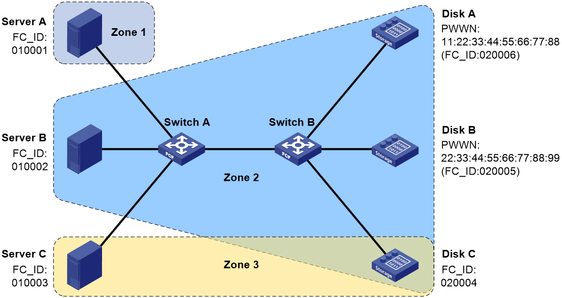
Requirements analysis
To meet the network requirements, divide VSAN 1 into three zones as follows:
· Assign Server A to Zone 1.
· Assign Server B and Disks A, B, and C to Zone 2.
· Assign Server C and Disk B to Zone 3.
· Enable Pairwise for Zone 2 because Zone 2 has one server and multiple disks. Configure Server B as an initiator, and configure Disks A, B, and C as targets.
· Create a zone set named Zoneset1, which contains zones Zone1, Zone2, and Zone3, and activate it.
Procedure
|
|
IMPORTANT: By default, interfaces on the device are disabled (in ADM or Administratively Down state). To have an interface operate, you must use the undo shutdown command to enable that interface. |
This section describes only FC zone configurations on Switch A. You do not need to configure FC zones on Switch B.
# Configure the switch to operate in advanced mode, save the configuration, and reboot the switch. (Skip this step if the switch is operating in advanced mode.)
<SwitchA> system-view
[SwitchA] system-working-mode advance
[SwitchA] save
[SwitchA] quit
<SwitchA> reboot
# Configure the switch to operate in FCF mode.
<SwitchA> system-view
[SwitchA] fcoe-mode fcf
# Enable the enhanced zoning mode in VSAN 1.
[SwitchA] vsan 1
[SwitchA-vsan1] zone mode enhanced
The zoning database in this switch would be distributed throughout the fabric. Continue? [Y/N]:y
[SwitchA-vsan1]
# Create a zone alias named Alias1.
[SwitchA-vsan1] zone-alias name Alias1
# Create a zone named Zone1, and specify FC address 010001 as its member.
[SwitchA-vsan1] zone name Zone1
[SwitchA-vsan1-zone-Zone1] member fcid 010001
[SwitchA-vsan1-zone-Zone1] quit
# Create a zone named Zone2, and enable the Pairwise feature for Zone2.
[SwitchA-vsan1] zone name Zone2
[SwitchA-vsan1-zone-Zone2] pairwise-zoning enable
# Specify FC address 010002 as its initiator member.
[SwitchA-vsan1-zone-Zone2] member fcid 010002 initiator
# Specify pWWNs 11:22:33:44:55:66:77:88 and 22:33:44:55:66:77:88:99 as its target members.
[SwitchA-vsan1-zone-Zone2] member pwwn 11:22:33:44:55:66:77:88 target
[SwitchA-vsan1-zone-Zone2] member pwwn 22:33:44:55:66:77:88:99 target
# Specify FC address 020004 as its target member.
[SwitchA-vsan1-zone-Zone2] member fcid 020004 target
[SwitchA-vsan1-zone-Zone2] quit
# Create a zone named Zone3, and specify FC addresses 010003 and 020004 as members of Zone3.
[SwitchA-vsan1] zone name Zone3
[SwitchA-vsan1-zone-Zone3] member fcid 010003
[SwitchA-vsan1-zone-Zone3] member fcid 020004
[SwitchA-vsan1-zone-Zone3] quit
# Create a zone set named Zoneset1 and add zones Zone1, Zone2, and Zone3 as its members.
[SwitchA-vsan1] zoneset name Zoneset1
[SwitchA-vsan1-zoneset-Zoneset1] member Zone1
[SwitchA-vsan1-zoneset-Zoneset1] member Zone2
[SwitchA-vsan1-zoneset-Zoneset1] member Zone3
[SwitchA-vsan1-zoneset-Zoneset1] quit
# Activate a zone set as the active zone set and distribute it to the entire fabric.
[SwitchA-vsan1] zoneset activate name Zoneset1
Verifying the configuration
Perform all verification tasks on Switch B.
# Display zone set information for VSAN 1.
<SwitchB> display zoneset vsan 1
VSAN 1:
zoneset name Zoneset1
zone name Zone1
fcid 0x010001
zone name Zone2
fcid 0x010002 initiator
fcid 0x020004 target
pwwn 11:22:33:44:55:66:77:88 target
pwwn 22:33:44:55:66:77:88:99 target
zone name Zone3
fcid 0x010003
fcid 0x020004 target
# Display information about Zone 2 in VSAN 1.
<SwitchB> display zone name Zone2 vsan 1
VSAN 1:
zone name Zone2
fcid 0x010002 initiator
fcid 0x020004 target
pwwn 11:22:33:44:55:66:77:88 target
pwwn 22:33:44:55:66:77:88:99 target
# Display the zone to which 020004 (FC address type) belongs.
<SwitchB> display zone member fcid 020004
fcid 0x020004
VSAN 1:
zone Zone2
zone Zone3
# Display information about the active zone set in VSAN 1.
<SwitchB> display zoneset active vsan 1
VSAN 1:
zoneset name Zoneset1
zone name Zone1
*fcid 0x010001
zone name Zone2
*fcid 0x010002
*fcid 0x020004
*fcid 0x020005 [pwwn 22:33:44:55:66:77:88:99]
*fcid 0x020006 [pwwn 11:22:33:44:55:66:77:88]
zone name Zone3
*fcid 0x010003
*fcid 0x020004
Configuring FIP snooping
About FIP snooping
Background
To communicate with devices in the FC SAN, a node must register with an FC fabric. An FC switch has point-to-point connections with nodes. An FC switch brings up an interface connected to a node only after the node completes fabric login on the interface.
In an FCoE implementation, Transit switches can be present between ENodes and FCF switches, so the connections between ENodes and FCF switches are no longer point-to-point. In this case, a node that has not performed fabric login might communicate with the FC SAN. For example, two ENodes are connected to one FCF switch through a Transit switch. After one ENode has registered with the FCF switch and the corresponding interface is brought up, the other ENode can also communicate with the FC SAN.
FCoE Initialization Protocol Snooping (FIP snooping) is a security feature that can run only on Transit switches in an FCoE network.
Role of FIP snooping
By checking source MAC addresses of FCoE frames, FIP snooping enables a Transit switch to forward FCoE frames only between the following elements:
· An ENode that has performed fabric login.
· The FCF switch that has accepted its fabric login.
FIP snooping network diagram
Figure 36 shows a typical FIP snooping network diagram.

Ethernet interfaces on a Transit switch can operate in ENode or FCF mode. An Ethernet interface connected to an ENode must be configured to operate in ENode mode. An Ethernet interface connected to an FCF switch must be configured to operate in FCF mode.
To control packet exchange between ENodes and FCF switches, perform the following tasks on the Transit switch:
· Enable FIP snooping.
· Configure the Ethernet interfaces to operate in a correct mode.
How FIP snooping works
After FIP snooping is enabled for a VLAN, Ethernet interfaces on the Transit switch establish FIP snooping rules according to FIP frames (with EtherType as 0x8914). Then, the Ethernet interfaces control the forwarding of FCoE frames (with EtherType as 0x8906) based on the FIP snooping rules.
To facilitate description, the following definitions are specified:
· FIP snooping rules generated on an Ethernet interface operating in FCF mode are called FCF FIP snooping rules.
· FIP snooping rules generated on an Ethernet interface operating in ENode mode are called ENode FIP snooping rules.
Establishing FIP snooping rules
FIP snooping rules are established when a virtual link is established between an ENode and an FCF switch. The following workflow is used to establish FIP snooping rules:
1. After receiving an unsolicited Discovery Advertisement from an FCF switch, the Ethernet interface in FCF mode on the Transit switch performs the following operations:
a. Generates an FCF FIP snooping rule based on the unsolicited Discovery Advertisement.
b. Forwards the unsolicited Discovery Advertisement to the ENode.
The FCF FIP snooping rule allows FCoE frames meeting the following requirements to pass through:
¡ The source MAC address is the MAC address in the unsolicited Discovery Advertisement (FCoE MAC address of the FCF switch).
¡ The 24 most significant bits of the destination MAC address is the FC-MAP value configured for the VLAN.
2. The Transit switch receives a Discovery Solicitation from the ENode on the Ethernet interface in ENode mode.
3. The Transit switch forwards the Discovery Solicitation to the FCF switch through the Ethernet interface in FCF mode.
4. The Transit switch receives a FIP FLOGI request from the ENode on the Ethernet interface in ENode mode.
5. The Transit switch forwards the FIP FLOGI request to the FCF switch through the Ethernet interface in FCF mode.
6. When forwarding the FLOGI LS_ACC packet from the FCF switch to the ENode, the Ethernet interface in ENode mode performs the following operations:
a. Obtains the FC address assigned by the FCF switch to the ENode and the FCoE MAC address of the FCF switch.
b. Generates an ENode FIP snooping rule.
The ENode FIP snooping rule allows FCoE frames meeting the following requirements to pass through:
¡ The source MAC address is the FPMA (with FC-MAP as the 24 most significant bits and FC address as the 24 least significant bits).
¡ The destination MAC address is the FCoE MAC address of the FCF switch.
FIP snooping rules exist as long as the virtual link is present, and they are deleted when you delete the virtual link.
Controlling forwarding of FCoE frames
After establishing FIP snooping rules, a Transit switch forwards only FCoE frames that match FIP snooping rules. As a result, only successfully registered ENodes can communicate with FCF switches.
FIP snooping tasks at a glance
To configure FIP snooping, perform the following tasks:
2. Configuring the operating mode of an Ethernet interface
3. (Optional.) Setting the FC-MAP value for a VLAN
Enabling FIP snooping
About this task
After FIP snooping is enabled for a VLAN, Ethernet interfaces on the Transit switch establish FIP snooping rules according to FIP frames. Then, the Ethernet interfaces control the forwarding of FCoE frames based on the FIP snooping rules.
Procedure
1. Enter system view.
system-view
2. Enter VLAN view.
vlan vlan-id
3. Enable FIP snooping for the VLAN.
fip-snooping enable
By default, FIP snooping is disabled for each VLAN.
Configuring the operating mode of an Ethernet interface
About this task
Ethernet interfaces on a Transit switch can operate in ENode mode or FCF mode. An Ethernet interface connected to an ENode must be configured to operate in ENode mode. An Ethernet interface connected to an FCF switch must be configured to operate in FCF mode.
Restrictions and guidelines
This feature does not take effect on member ports of a Layer 2 aggregate interface.
Procedure
1. Enter system view.
system-view
2. Enter Layer 2 Ethernet interface view or Layer 2 aggregate interface view.
interface interface-type interface-number
3. Configure the operating mode of the interface.
fip-snooping port-mode { enode | fcf }
The default setting is ENode mode.
Setting the FC-MAP value for a VLAN
About this task
The FC-MAP value identifies an FCoE network. Switches (including FCF switches and Transit switches) in the same FCoE network must have the same FC-MAP value.
You can use the fcoe fcmap command to set the FC-MAP value in frames sent out of an FCF switch. You can use the fip-snooping fc-map command to set an FC-MAP value for a VLAN on a Transit switch.
When an Ethernet interface in the FIP snooping VLAN receives a frame from the FCF switch, the following rules apply:
· If the FC-MAP value in the incoming frame is the same as that configured for the FIP snooping VLAN, the Ethernet interface forwards the frames.
· If the FC-MAP value in the incoming frame is different from that configured for the FIP snooping VLAN, the Ethernet interface drops the frames.
Procedure
1. Enter system view.
system-view
2. Enter VLAN view.
vlan vlan-id
3. Set an FC-MAP value for the VLAN.
fip-snooping fc-map fc-map
The default setting is 0x0efc00.
Display and maintenance commands for FIP snooping
Execute display commands in any view.
|
Task |
Command |
|
Display ENode information obtained by a Transit switch. |
display fip-snooping enode [ vlan vlan-id ] |
|
Display FCF switch information obtained by a Transit switch. |
display fip-snooping fcf [ vlan vlan-id ] |
|
Display the FIP snooping rules that are being flushed. |
display fip-snooping flushing-rules [ enode | fcf ] [ vlan vlan-id ] |
|
Display the FIP snooping rules that have been flushed. |
In standalone mode: display fip-snooping rules [ enode | fcf ] [ vlan vlan-id ] [ slot slot-number ] In IRF mode: display fip-snooping rules [ enode | fcf ] [ vlan vlan-id ] [ chassis chassis-number slot slot-number ] |
|
Display information about FIP snooping sessions (connections between ENodes and FCF switches). |
display fip-snooping sessions [ vlan vlan-id ] |
FIP snooping configuration examples
Example: Configuring FIP snooping
Network configuration
As shown in Figure 37, enable FIP snooping on the Transit switch for reliable communication between the ENode and FCF switch.

Procedure
|
|
IMPORTANT: By default, interfaces on the device are disabled (in ADM or Administratively Down state). To have an interface operate, you must use the undo shutdown command to enable that interface. |
1. Configure the Transit switch:
# Configure the switch to operate in advanced mode, save the configuration, and reboot the switch. (Skip this step if the switch is operating in advanced mode.)
<Transit> system-view
[Transit] system-working-mode advance
[Transit] save
[Transit] quit
<Transit> reboot
# Configure the switch to operate in Transit mode.
<Transit> system-view
[Transit] fcoe-mode transit
# Enable FIP snooping for VLAN 10.
[Transit] vlan 10
[Transit-vlan10] fip-snooping enable
# Set the FC-MAP value to 0x0efc01 for VLAN 10.
[Transit-vlan10] fip-snooping fc-map 0efc01
Changing the FC-MAP will flap all interfaces. Continue? [Y/N]:y
[Transit-vlan10] quit
# Configure FortyGigE 1/0/1 to allow VLAN 10.
[Transit] interface fortygige 1/0/1
[Transit-FortyGigE1/0/1] port link-type trunk
[Transit-FortyGigE1/0/1] port trunk permit vlan 10
# Configure FortyGigE 1/0/1 to operate in FCF mode.
[Transit-FortyGigE1/0/1] fip-snooping port-mode fcf
[Transit-FortyGigE1/0/1] quit
# Configure FortyGigE 1/0/2 to allow VLAN 10.
[Transit] interface fortygige 1/0/2
[Transit-FortyGigE1/0/2] port link-type trunk
[Transit-FortyGigE1/0/2] port trunk permit vlan 10
# Configure FortyGigE 1/0/2 to operate in ENode mode.
[Transit-FortyGigE1/0/2] fip-snooping port-mode enode
[Transit-FortyGigE1/0/2] quit
2. Configure the FCF switch:
# Configure the switch to operate in advanced mode, save the configuration, and reboot the switch. (Skip this step if the switch is operating in advanced mode.)
<FCF> system-view
[FCF] system-working-mode advance
[FCF] save
[FCF] quit
<FCF> reboot
# Configure the switch to operate in FCF mode.
<FCF> system-view
[FCF] fcoe-mode fcf
# Set the FC-MAP value to 0x0efc01.
[FCF] fcoe fcmap 0efc01
Changing the FC-MAP will flap all VFC interfaces. Continue? [Y/N]:y
# Create VSAN 10.
[FCF] vsan 10
[FCF-vsan10] quit
# Create VFC 1.
[FCF] interface vfc 1
# Configure the mode of VFC 1 as F.
[FCF-vfc1] fc mode f
# Assign VFC 1 to VSAN 10.
[FCF-vfc1] port trunk vsan 10
# Bind VFC 1 to FortyGigE 1/0/1.
[FCF-vfc1] bind interface fortygige 1/0/1
[FCF-Vfc1] quit
# Configure FortyGigE 1/0/1 as a trunk port, and assign the port to VLAN 10.
[FCF] interface fortygige 1/0/1
[FCF-FortyGigE1/0/1] port link-type trunk
[FCF-FortyGigE1/0/1] port trunk permit vlan 10
[FCF-FortyGigE1/0/1] quit
# Enable FC and FCoE in VLAN 10 and map VLAN 10 to VSAN 10.
[FCF] vlan 10
[FCF-vlan10] fcoe enable vsan 10
Verifying the configuration
# Display ENode information obtained by the Transit switch.
[Transit] display fip-snooping enode
VLAN 10:
Interface ENode WWN ENode MAC
FGE1/0/2 10:00:00:11:22:00:0d:01 0000-1234-0d01
# Display FCF switch information obtained by the Transit switch.
[Transit] display fip-snooping fcf
VLAN 10:
Interface FCF MAC FCF WWN Fabric Name ENode
FGE1/0/1 0000-1234-0e01 10:00:00:11:22:00:0e:01 10:00:00:11:22:00:0e:01 1
# Display information about FIP snooping sessions.
[Transit] display fip-snooping sessions
VLAN 10:
FCF MAC ENode MAC VN_Port MAC VN_Port WWN
0000-1234-0e01 0000-1234-0d01 0efc-0001-0000 af:10:01:11:22:00:0d:01
# Display the FIP snooping rules that have been flushed.
[Transit] display fip-snooping rules
Slot 1:
VLAN 10:
FCF rules information:
Interface Source MAC/Mask Destination MAC/Mask Context
XGE1/0/1 0000-1234-0e01/48 0efc-0000-0000/24 ffffffff
ENode rules information:
Interface Source MAC/Mask Destination MAC/Mask Context
XGE1/0/2 0efc-0001-0000/48 0000-1234-0e01/48 ffffffff
Configuring port security
About port security
Typically, any device (a node or switch) in a SAN can log in to an FCF switch. The port security feature prevents unauthorized access to switch interfaces.
After you configure port security for a VSAN, the switch performs authorization checks on each device that attempts to log in based on the port security database.
· If the device passes the authorization checks, it is allowed to log in.
· If the device fails the authorization checks, it is denied.
Control scope
The port security feature allows you to control access of the following devices:
· An N_Port specified by its pWWN.
· An NP_Port specified by its pWWN.
· A node specified by its nWWN (represents all N_Ports on the node).
· An NPV switch specified by its nWWN (represents all NP_Ports on the NPV switch).
· An FCF switch specified by its sWWN.
Port security database
A port security database stores device-interface binding entries. An entry specifies the interfaces through which a device can log in. Device-interface binding entries can be statically configured or automatically learned.
After you enable auto learning, the switch automatically learns binding entries for devices that log in. Enable auto learning when devices are secure. Enabling auto learning reduces manual configuration.
Methods of enabling auto learning
You can enable auto learning by using either of the following methods:
· Enable auto learning while enabling port security. In this case, the switch learns binding entries for both devices already logged in and devices newly logged in. If you enable port security without enabling auto learning, devices already logged in are logged out.
· Enable auto learning separately. In this case, the switch learns binding entries for only devices newly logged in.
Binding entry types
A port security database has the following types of binding entries:
· Static entries—Manually configured and can overwrite learning and learned entries.
· Learning entries—Automatically learned entries. A learning entry does not affect device login and is deleted when the corresponding device logs out. Learning entries cannot overwrite static or learned entries.
· Learned entries—Converted from existing learning entries when auto learning is disabled. A learned entry affects device login and is not deleted when the corresponding device logs out.
· Smart SAN static entries—Manually configured for Smart SAN-capable nodes whose Smart SAN Security Support field is not 0x00. They can overwrite Smart SAN learning entries. Smart SAN learning entries are converted to Smart SAN static entries when Smart SAN auto learning is disabled.
· Smart SAN learning entries—Automatically learned for Smart SAN-capable nodes whose Smart SAN Security Support field is not 0x00. They cannot overwrite Smart SAN static entries. A Smart SAN learning entry does not affect device login and is deleted when the corresponding device logs out.
FC interfaces, FC aggregate interfaces, and VFC interfaces allow multiple devices to log in. If a device that does not have a binding entry logs in through a VFC interface, the port security feature shuts down the VFC interface. The devices that have logged in are also logged out.
Authorization checks
The switch determines whether to allow a device to log in by performing authorization checks as shown in Figure 38.
|
|
NOTE: Both static and learned binding entries affect device login. |
Figure 38 Authorization checks
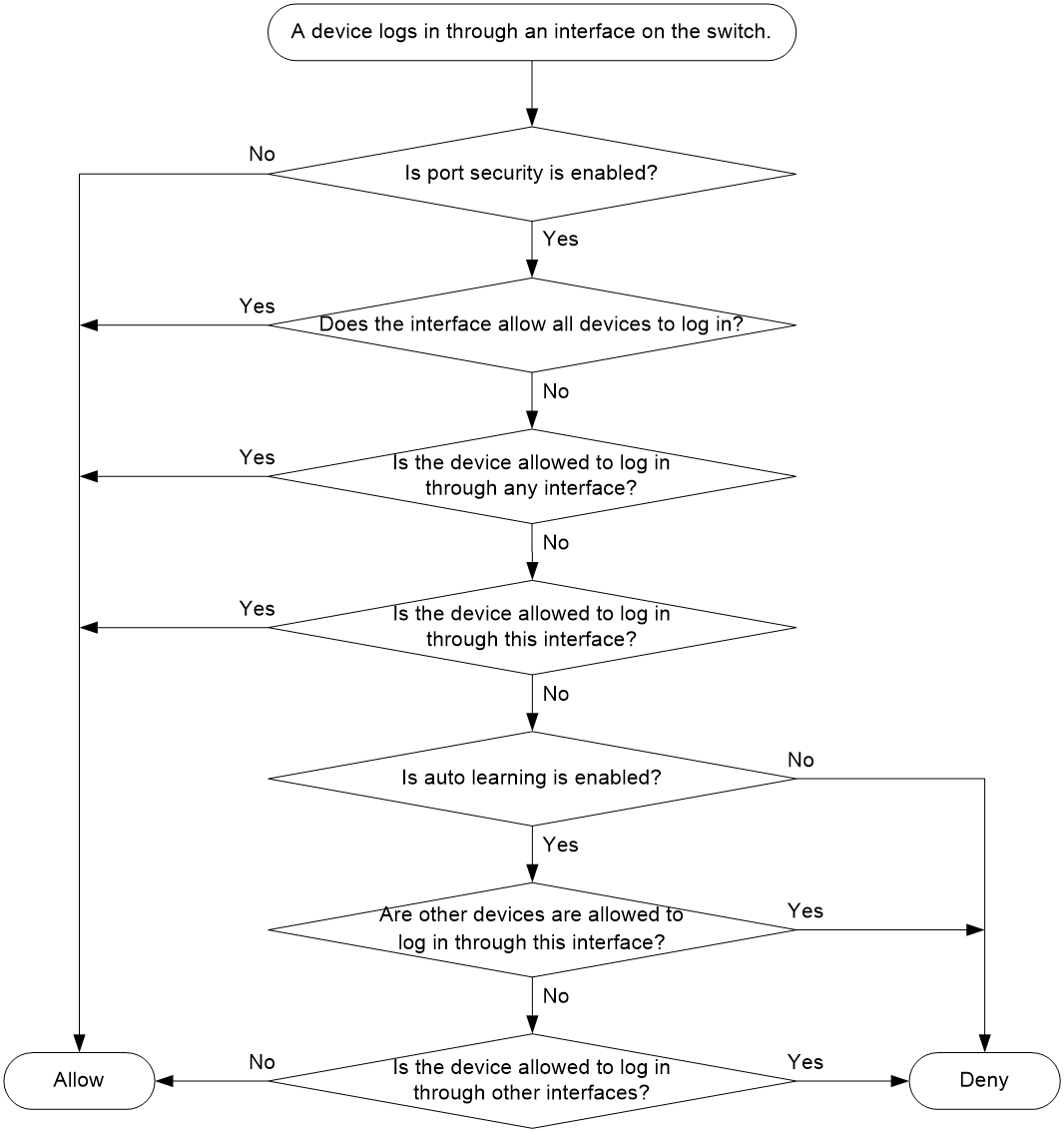
After the switch denies a device, the switch shuts down the F_Port or isolates the E_Port connecting to the device. In this case, the F_Port or E_Port will not restore its state automatically even if you configure the F_Port or E_Port to allow the device. To allow a denied device, perform the following tasks:
1. Configure a binding entry to allow the device.
2. Execute the undo shutdown command to bring up the F_Port, or execute the shutdown and undo shutdown commands to bring up the E_Port.
For an E_Port, you can also execute the undo port trunk vsan and port trunk vsan commands to remove its isolated state.
Port security tasks at a glance
To configure FIP snooping, perform the following tasks:
2. Configure a security policy
¡ Manually configuring binding entries
¡ Enabling auto learning or Smart SAN auto learning
3. (Optional.) Converting learned entries to static entries
4. (Optional.) Enabling SNMP notifications for port security
Enabling port security
About this task
When you enable port security, you can also enable auto learning. If you enable auto learning when enabling port security, the switch performs the following operations:
· Learns binding entries for both devices already logged in and devices newly logged in.
· Adds the entries to the port security database as learning entries.
When you enable port security, you can also enable Smart SAN auto learning. Smart SAN auto learning takes effect only when Smart SAN is enabled. If you enable Smart SAN auto learning when enabling port security, the switch performs the following operations:
· Learns binding entries for both already logged in and newly logged in nodes that are Smart SAN-capable and whose Smart SAN Security Support field is not 0x00.
· Adds the entries to the port security database as Smart SAN learning entries.
Restrictions and guidelines
You can configure other port security settings only after you enable port security.
If you do not enable auto learning or Smart SAN auto learning, devices already logged in are logged out.
If you do not enable auto learning but enable Smart SAN auto learning, the switch adds Smart SAN learning entries for only Smart SAN-capable nodes whose Smart SAN Security Support field is not 0x00. The switch does not add Smart SAN learning entries for Smart SAN-incapable nodes.
Prerequisites
Enable smart SAN for FC/FCoE before you specify the all or smartsan-learn keyword.
Procedure
1. Enter system view.
system-view
2. Enter VSAN view.
vsan vsan-id
3. Enable port security for the VSAN.
fc-port-security enable [ all | auto-learn | smartsan-learn ]
By default, port security is disabled for a VSAN.
Manually configuring binding entries
About this task
After you configure binding entries, a logged-in device remains logged in if it can pass authorization checks. If the device cannot pass authorization checks, it is logged out.
Restrictions and guidelines
After you add or delete a binding entry, the switch performs authorization checks on devices already logged in.
· If the device specified in the binding entry or a device on a specified interface passes authorization checks, the device is not logged out.
· Otherwise, the device is logged out.
Prerequisites
Enable port security before manually you configure binding entries.
Enable smart SAN for FC/FCoE before you specify the smartsan-static keyword.
Procedure
1. Enter system view.
system-view
2. Enter VSAN view.
vsan vsan-id
3. Allow a pWWN to log in through the specified interfaces.
pwwn pwwn [ interface interface-list ] [ smartsan-static ]
By default, a pWWN is not allowed to log in through the specified interfaces.
4. Allow an nWWN to log in through the specified interfaces.
nwwn nwwn [ interface interface-list ]
By default, an nWWN is not allowed to log in through the specified interfaces.
5. Allow an sWWN to log in through the specified interfaces.
swwn swwn [ interface interface-list ]
By default, an sWWN is not allowed to log in through the specified interfaces.
6. Allow any WWN to log in through the specified interfaces.
any-wwn interface interface-list
By default, WWNs are not allowed to log in through an interface.
Enabling auto learning or Smart SAN auto learning
About this task
You can enable both auto learning and Smart SAN auto learning in a VSAN.
After you enable auto learning, all devices that are newly logged in are learned and added to the port security database as learning entries. A learning entry does not affect device login and is deleted when the corresponding device logs out. When you disable auto learning, learning entries are converted to learned entries. A learned entry affects device login and is not deleted when the corresponding device logs out.
After you enable Smart SAN auto learning, the switch performs the following operations:
· Learns binding entries for newly logged in nodes that are Smart SAN-capable and whose Smart SAN Security Support field is not 0x00.
· Adds the entries to the port security database as Smart SAN learning entries.
A Smart SAN learning entry does not affect device login and is deleted when the corresponding device logs out. When you disable Smart SAN auto learning, Smart SAN learning entries are converted to Smart SAN static entries. A Smart SAN static entry affects device login and is not deleted when the corresponding device logs out.
Prerequisites
Enable port security before manually you enable auto learning or Smart SAN auto learning.
Enable smart SAN for FC/FCoE before you specify the smartsan-static keyword.
Procedure
1. Enter system view.
system-view
2. Enter VSAN view.
vsan vsan-id
3. Enable auto learning or Smart SAN auto learning for the VSAN.
fc-port-security { auto-learn | smartsan-learn }
By default, auto learning and Smart SAN auto learning are disabled in a VSAN.
Converting learned entries to static entries
About this task
Learned entries do not survive a reboot. To make learned entries survive reboots, convert the learned entries to static entries.
Prerequisites
Enable port security before converting learned entries to static entries.
Procedure
1. Enter system view.
system-view
2. Enter VSAN view.
vsan vsan-id
3. Convert learned entries to static entries in the VSAN.
fc-port-security database copy
By default, auto learning is disabled in a VSAN.
Enabling SNMP notifications for port security
About this task
After you enable SNMP notifications for port security, the port security module generates notifications for important events and sends the notifications to the SNMP module. For more information about SNMP notifications, see Network Management and Monitoring Configuration Guide.
Procedure
1. Enter system view.
system-view
2. Enable SNMP notifications for port security.
snmp-agent trap enable fc-port-security [ violation-happen ]
By default, all SNMP notifications for port security are disabled.
Display and maintenance commands for port security
Execute display commands in any view and reset commands in user view.
|
Task |
Command |
|
Display binding entries in the port security database. |
display fc-port-security database { all | auto-learn | smartsan-learn | smartsan-static | static } [ interface interface-type interface-number ] [ vsan vsan-id ] |
|
Display port security statistics. |
display fc-port-security statistics [ vsan vsan-id ] |
|
Display port security status. |
display fc-port-security status [ vsan vsan-id ] |
|
Display security violation entries. |
display fc-port-security violation [ vsan vsan-id ] |
|
Clear binding entries in the port security database. |
reset fc-port-security database { all | auto-learn | smartsan-static | static } [ interface interface-type interface-number ] vsan vsan-id |
|
Clear port security statistics. |
reset fc-port-security statistics vsan vsan-id |
Port security configuration examples
Example: Configuring port security by using FC interfaces
Network configuration
As shown in Figure 39, the pWWN and nWWN of Server A are 20:36:44:78:66:77:ab:97 and 10:36:44:78:66:77:ab:97, respectively. The pWWN and nWWN of Server B are 20:33:44:78:66:77:ab:96 and 10:33:44:78:66:77:ab:96, respectively. The sWWNs of Switch A, Switch B, and Switch C are 10:83:45:87:66:19:ea:91, 10:83:45:87:66:19:bc:92, and 10:83:45:87:66:19:bc:93, respectively.
Configure port security to meet the following requirements:
· Switch A, Server A, and Switch C can access one another.
· Switch B, Server B, and Switch C cannot access one another.
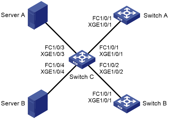
Procedure
|
|
IMPORTANT: By default, interfaces on the device are disabled (in ADM or Administratively Down state). To have an interface operate, you must use the undo shutdown command to enable that interface. |
This example describes only FC interface configurations.
1. Configure Switch C:
# Configure the switch to operate in advanced mode, save the configuration, and reboot the switch. (Skip this step if the switch is operating in advanced mode.)
<SwitchC> system-view
[SwitchC] system-working-mode advance
[SwitchC] save
[SwitchC] quit
<SwitchC> reboot
# Configure the switch to operate in FCF mode.
<SwitchC> system-view
[SwitchC] fcoe-mode fcf
# Create VSAN 2.
[SwitchC] vsan 2
[SwitchC-vsan2] quit
# Change FortyGigE 1/0/1 to FC 1/0/1.
[SwitchC] interface fortygige 1/0/1
[SwitchC-FortyGigE1/0/1] port-type fc
# Configure FC 1/0/1 to operate in E mode and to autonegotiate the speed.
[SwitchC-Fc1/0/1] fc mode e
[SwitchC-Fc1/0/1] speed auto
# Assign FC 1/0/1 to VSAN 2 as an access port.
[SwitchC-Fc1/0/1] port access vsan 2
[SwitchC-Fc1/0/1] quit
# Change FortyGigE 1/0/2 to FC 1/0/2.
[SwitchC] interface fortygige 1/0/2
[SwitchC-FortyGigE1/0/2] port-type fc
# Configure FC 1/0/2 to operate in E mode and to autonegotiate the speed.
[SwitchC-Fc1/0/2] fc mode e
[SwitchC-Fc1/0/2] speed auto
# Assign FC 1/0/2 to VSAN 2 as an access port.
[SwitchC-Fc1/0/2] port access vsan 2
[SwitchC-Fc1/0/2] quit
# Change FortyGigE 1/0/3 to FC 1/0/3.
[SwitchC] interface fortygige 1/0/3
[SwitchC-FortyGigE1/0/3] port-type fc
# Configure FC 1/0/3 to operate in F mode and to autonegotiate the speed.
[SwitchC-Fc1/0/3] fc mode f
[SwitchC-Fc1/0/3] speed auto
# Assign FC 1/0/3 to VSAN 2 as an access port.
[SwitchC-Fc1/0/3] port access vsan 2
[SwitchC-Fc1/0/3] quit
# Change FortyGigE 1/0/4 to FC 1/0/4.
[SwitchC] interface fortygige 1/0/4
[SwitchC-FortyGigE1/0/4] port-type fc
# Configure FC 1/0/4 to operate in F mode and to autonegotiate the speed.
[SwitchC-Fc1/0/4] fc mode f
[SwitchC-Fc1/0/4] speed auto
# Assign FC 1/0/4 to VSAN 2 as an access port.
[SwitchC-Fc1/0/4] port access vsan 2
[SwitchC-Fc1/0/4] quit
# Enable FC and FCoE in VLAN 2 and map VLAN 2 to VSAN 2.
[SwitchC] vlan 2
[SwitchC-vlan2] fcoe enable vsan 2
[SwitchC-vlan2] quit
# Enable port security and auto learning in VSAN 2.
[SwitchC] vsan 2
[SwitchC-vsan2] fc-port-security enable auto-learn
# Allow Switch A to log in through FC 1/0/1 and FC 1/0/2 in VSAN 2.
[SwitchC-vsan2] swwn 10:83:45:87:66:19:ea:91 interface fc 1/0/1 to fc 1/0/2
# Allow Server A to log in through FC 1/0/3 and FC 1/0/4 in VSAN 2.
[SwitchC-vsan2] nwwn 20:36:44:78:66:77:ab:97 interface fc 1/0/3 to fc 1/0/4
[SwitchC-vsan2] quit
2. Configure Switch A:
# Configure the switch to operate in advanced mode, save the configuration, and reboot the switch. (Skip this step if the switch is operating in advanced mode.)
<SwitchA> system-view
[SwitchA] system-working-mode advance
[SwitchA] save
[SwitchA] quit
<SwitchA> reboot
# Configure the switch to operate in FCF mode.
<SwitchA> system-view
[SwitchA] fcoe-mode fcf
# Create VSAN 2.
[SwitchA] vsan 2
[SwitchA-vsan2] quit
# Change FortyGigE 1/0/1 to FC 1/0/1.
[SwitchA] interface fortygige 1/0/1
[SwitchA-FortyGigE1/0/1] port-type fc
# Configure FC 1/0/1 to operate in E mode and to autonegotiate the speed.
[SwitchA-Fc1/0/1] fc mode e
[SwitchA-Fc1/0/1] speed auto
# Assign FC 1/0/1 to VSAN 2 as an access port.
[SwitchA-Fc1/0/1] port access vsan 2
[SwitchA-Fc1/0/1] quit
# Enable FC and FCoE in VLAN 2 and map VLAN 2 to VSAN 2.
[SwitchA] vlan 2
[SwitchA-vlan2] fcoe enable vsan 2
[SwitchA-vlan2] quit
# Enable port security and auto learning in VSAN 2.
[SwitchA] vsan 2
[SwitchA-vsan2] fc-port-security enable auto-learn
# Allow Switch C to log in through FC 1/0/1.
[SwitchA-vsan2] swwn 10:83:45:87:66:19:bc:93 interface fc 1/0/1
3. Configure Switch B:
# Configure the switch to operate in advanced mode, save the configuration, and reboot the switch. (Skip this step if the switch is operating in advanced mode.)
<SwitchB> system-view
[SwitchB] system-working-mode advance
[SwitchB] save
[SwitchB] quit
<SwitchB> reboot
# Configure the switch to operate in FCF mode.
<SwitchB> system-view
[SwitchB] fcoe-mode fcf
# Create VSAN 2.
[SwitchB] vsan 2
[SwitchB-vsan2] quit
# Change FortyGigE 1/0/1 to FC 1/0/1.
[SwitchB] interface fortygige 1/0/1
[SwitchB-FortyGigE1/0/1] port-type fc
# Configure FC 1/0/1 to operate in E mode and to autonegotiate the speed.
[SwitchB-Fc1/0/1] fc mode e
[SwitchB-Fc1/0/1] speed auto
# Assign FC 1/0/1 to VSAN 2 as an access port.
[SwitchB-Fc1/0/1] port access vsan 2
[SwitchB-Fc1/0/1] quit
# Enable FC and FCoE in VLAN 2 and map VLAN 2 to VSAN 2.
[SwitchB] vlan 2
[SwitchB-vlan2] fcoe enable vsan 2
[SwitchB-vlan2] quit
# Enable port security and auto learning in VSAN 2.
[SwitchB] vsan 2
[SwitchB-vsan2] fc-port-security enable auto-learn
# Configure FC 1/0/1 to deny Switch C (Configure FC 1/0/1 to allow any sWWN other than the WWN of Switch C).
[SwitchB-vsan2] swwn 10:83:45:87:66:19:ea:91 interface fc 1/0/1
Verifying the configuration
# Display security violation entries in VSAN 2 on Switch C.
[SwitchC] display fc-port-security violation vsan 2
Total entries: 2
Violations for VSAN 2:
Interface Logging-in entity Last time Repeat count
Fc1/0/2 10:83:45:87:66:19:bc:92(sWWN) 2013/12/10 13:20:20 1
Fc1/0/4 20:33:44:78:66:77:ab:96(pWWN) 2013/10/10 12:55:10 1
10:33:44:78:66:77:ab:96(nWWN)
The output shows that Switch C denied Server B and Switch B. If Switch C initiates a login request to Switch B, the violation entry for Switch B does not appear in this output. Instead, a violation entry for Switch C appears in the output from this command on Switch B.
Example: Configuring port security by using VFC interfaces
Network configuration
As shown in Figure 40, the pWWN and nWWN of Server A are 20:36:44:78:66:77:ab:97 and 10:36:44:78:66:77:ab:97, respectively. The pWWN and nWWN of Server B are 20:33:44:78:66:77:ab:96 and 10:33:44:78:66:77:ab:96, respectively. The sWWNs of Switch A, Switch B, and Switch C are 10:83:45:87:66:19:ea:91, 10:83:45:87:66:19:bc:92, and 10:83:45:87:66:19:bc:93, respectively.
Configure port security to meet the following requirements:
· Switch A, Server A, and Switch C can access one another.
· Switch B, Server B, and Switch C cannot access one another.
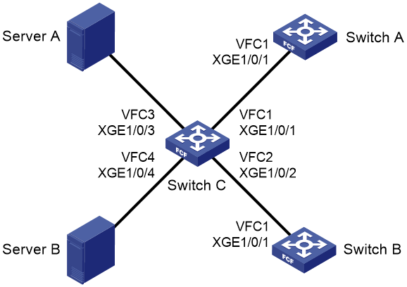
Procedure
|
|
IMPORTANT: By default, interfaces on the device are disabled (in ADM or Administratively Down state). To have an interface operate, you must use the undo shutdown command to enable that interface. |
This example describes only VFC interface configurations.
1. Configure Switch C:
# Configure the switch to operate in advanced mode, save the configuration, and reboot the switch. (Skip this step if the switch is operating in advanced mode.)
<SwitchC> system-view
[SwitchC] system-working-mode advance
[SwitchC] save
[SwitchC] quit
<SwitchC> reboot
# Configure the switch to operate in FCF mode.
<SwitchC> system-view
[SwitchC] fcoe-mode fcf
# Create VSAN 2.
[SwitchC] vsan 2
[SwitchC-vsan2] quit
# Create VFC 1, and configure VFC 1 to operate in E mode.
[SwitchC] interface vfc 1
[SwitchC-Vfc1] fc mode e
# Bind VFC 1 to FortyGigE 1/0/1, and assign VFC 1 to VSAN 2 as a trunk port.
[SwitchC-Vfc1] bind interface fortygige 1/0/1
[SwitchC-Vfc1] port trunk vsan 2
[SwitchC-Vfc1] quit
# Configure FortyGigE 1/0/1 to allow VLAN 2.
[SwitchC] interface fortygige 1/0/1
[SwitchC-FortyGigE1/0/1] port link-type trunk
[SwitchC-FortyGigE1/0/1] port trunk permit vlan 2
[SwitchC-FortyGigE1/0/1] quit
# Create VFC 2, and configure VFC 2 to operate in E mode.
[SwitchC] interface vfc 2
[SwitchC-Vfc2] fc mode e
# Bind VFC 2 to FortyGigE 1/0/2, and assign VFC 2 to VSAN 2 as a trunk port.
[SwitchC-Vfc2] bind interface fortygige 1/0/2
[SwitchC-Vfc2] port trunk vsan 2
[SwitchC-Vfc2] quit
# Configure FortyGigE 1/0/2 to allow VLAN 2.
[SwitchC] interface fortygige 1/0/2
[SwitchC-FortyGigE1/0/2] port link-type trunk
[SwitchC-FortyGigE1/0/2] port trunk permit vlan 2
[SwitchC-FortyGigE1/0/2] quit
# Create VFC 3, and configure VFC 3 to operate in F mode.
[SwitchC] interface vfc 3
[SwitchC-Vfc3] fc mode f
# Bind VFC 3 to FortyGigE 1/0/3, and assign VFC 3 to VSAN 2 as a trunk port.
[SwitchC-Vfc3] bind interface fortygige 1/0/3
[SwitchC-Vfc3] port trunk vsan 2
[SwitchC-Vfc3] quit
# Configure FortyGigE 1/0/3 to allow VLAN 2.
[SwitchC] interface fortygige 1/0/3
[SwitchC-FortyGigE1/0/3] port link-type trunk
[SwitchC-FortyGigE1/0/3] port trunk permit vlan 2
[SwitchC-FortyGigE1/0/3] quit
# Create VFC 4, and configure VFC 4 to operate in F mode.
[SwitchC] interface vfc 4
[SwitchC-Vfc4] fc mode f
# Bind VFC 4 to FortyGigE 1/0/4, and assign VFC 4 to VSAN 2 as a trunk port.
[SwitchC-Vfc4] bind interface fortygige 1/0/4
[SwitchC-Vfc4] port trunk vsan 2
[SwitchC-Vfc4] quit
# Configure FortyGigE 1/0/4 to allow VLAN 2.
[SwitchC] interface fortygige 1/0/4
[SwitchC-FortyGigE1/0/4] port link-type trunk
[SwitchC-FortyGigE1/0/4] port trunk permit vlan 2
[SwitchC-FortyGigE1/0/4] quit
# Enable FC and FCoE in VLAN 2 and map VLAN 2 to VSAN 2.
[SwitchC] vlan 2
[SwitchC-vlan2] fcoe enable vsan 2
[SwitchC-vlan2] quit
# Enable port security and auto learning in VSAN 2.
[SwitchC] vsan 2
[SwitchC-vsan2] fc-port-security enable auto-learn
# Allow Switch A to log in through VFC 1 and VFC 2 in VSAN 2.
[SwitchC-vsan2] swwn 10:83:45:87:66:19:ea:91 interface vfc 1 to vfc 2
# Allow Server A to log in through VFC 3 and VFC 4 in VSAN 2.
[SwitchC-vsan2] nwwn 20:36:44:78:66:77:ab:97 interface vfc 3 to vfc 4
[SwitchC-vsan2] quit
2. Configure Switch A:
# Configure the switch to operate in advanced mode, save the configuration, and reboot the switch. (Skip this step if the switch is operating in advanced mode.)
<SwitchA> system-view
[SwitchA] system-working-mode advance
[SwitchA] save
[SwitchA] quit
<SwitchA> reboot
# Configure the switch to operate in FCF mode.
<SwitchA> system-view
[SwitchA] fcoe-mode fcf
# Create VSAN 2.
[SwitchA] vsan 2
[SwitchA-vsan2] quit
# Create VFC 1, and configure VFC 1 to operate in E mode.
[SwitchA] interface vfc 1
[SwitchA-Vfc1] fc mode e
# Bind VFC 1 to FortyGigE 1/0/1, and assign VFC 1 to VSAN 2 as a trunk port.
[SwitchA-Vfc1] bind interface fortygige 1/0/1
[SwitchA-Vfc1] port trunk vsan 2
[SwitchA-Vfc1] quit
# Configure FortyGigE 1/0/1 to allow VLAN 2.
[SwitchA] interface fortygige 1/0/1
[SwitchA-FortyGigE1/0/1] port link-type trunk
[SwitchA-FortyGigE1/0/1] port trunk permit vlan 2
[SwitchA-FortyGigE1/0/1] quit
# Enable FC and FCoE in VLAN 2 and map VLAN 2 to VSAN 2.
[SwitchA] vlan 2
[SwitchA-vlan2] fcoe enable vsan 2
[SwitchA-vlan2] quit
# Enable port security and auto learning in VSAN 2.
[SwitchA] vsan 2
[SwitchA-vsan2] fc-port-security enable auto-learn
# Allow Switch C to log in through interface VFC 1.
[SwitchA-vsan2] swwn 10:83:45:87:66:19:bc:93 interface vfc 1
3. Configure Switch B:
# Configure the switch to operate in advanced mode, save the configuration, and reboot the switch. (Skip this step if the switch is operating in advanced mode.)
<SwitchB> system-view
[SwitchB] system-working-mode advance
[SwitchB] save
[SwitchB] quit
<SwitchB> reboot
# Configure the switch to operate in FCF mode.
<SwitchB> system-view
[SwitchB] fcoe-mode fcf
# Create VSAN 2.
[SwitchB] vsan 2
[SwitchB-vsan2] quit
# Create VFC 1, and configure VFC 1 to operate in E mode.
[SwitchB] interface vfc 1
[SwitchB-Vfc1] fc mode e
# Bind VFC 1 to FortyGigE 1/0/1, and assign VFC 1 to VSAN 2 as a trunk port.
[SwitchB-Vfc1] bind interface fortygige 1/0/1
[SwitchB-Vfc1] port trunk vsan 2
[SwitchB-Vfc1] quit
# Configure FortyGigE 1/0/1 to allow VLAN 2.
[SwitchB] interface fortygige 1/0/1
[SwitchB-FortyGigE1/0/1] port link-type trunk
[SwitchB-FortyGigE1/0/1] port trunk permit vlan 2
[SwitchB-FortyGigE1/0/1] quit
# Enable FC and FCoE in VLAN 2 and map VLAN 2 to VSAN 2.
[SwitchB] vlan 2
[SwitchB-vlan2] fcoe enable vsan 2
[SwitchB-vlan2] quit
# Enable port security and auto learning in VSAN 2.
[SwitchB] vsan 2
[SwitchB-vsan2] fc-port-security enable auto-learn
# Configure VFC 1 to deny Switch C in VSAN 2 (Configure VFC 1 to allow any sWWN other than the WWN of Switch C).
[SwitchB-vsan2] swwn 10:83:45:87:66:19:ea:91 interface vfc 1
Verifying the configuration
# Display security violation entries in VSAN 2 on Switch C.
[SwitchC] display fc-port-security violation vsan 2
Total entries: 2
Violations for VSAN 2:
Interface Logging-in entity Last time Repeat count
Vfc2 10:83:45:87:66:19:bc:92(sWWN) 2013/12/10 13:20:20 1
Vfc4 20:33:44:78:66:77:ab:96(pWWN) 2013/10/10 12:55:10 1
10:33:44:78:66:77:ab:96(nWWN)
The output shows that Switch C denied Server B and Switch B. If Switch C initiates a login request to Switch B, the violation entry for Switch B does not appear in this output. Instead, a violation entry for Switch C appears in the output from this command on Switch B.
Configuring FCS
About FCS
The Fabric Configuration Server (FCS) feature discovers topology information of a fabric, including switches in the fabric and ports on each switch. A management application (for example, SNMP software) determines the physical and logical topologies of the fabric based on the FCS topology information. It also manages the switches in the fabric.
Topology discovery process
The topology discovery process is as follows:
1. Each switch in a fabric maintains a list of all IE objects in the fabric. When no topology discovery is in progress in a VSAN, the switch displays the topology discovery status as localOnly in the VSAN. The switch stores all IE attributes and port attributes of its own and stores IE WWN, IE type, and domain ID attributes of other switches.
2. When a topology discovery is started, the switch changes the topology discovery status to inProgress in the VSAN. The switch obtains the latest IE attributes and port attributes of all other switches in the fabric and updates them to the local FCS database.
3. When the topology discovery is complete, the switch changes the topology discovery status to completed in the VSAN. The switch starts an aging timer to specify the amount of time for the topology discovery information to be retained.
4. When the aging timer expires, the switch performs the following operations:
¡ Deletes all topology discovery information except its own information.
¡ Changes the topology discovery status in the relevant VSAN to localOnly.
The fabric topology might change. During a topology discovery process, the switch does not obtain the following attributes:
· IE attributes and port attributes of an IE that joins the fabric after the switch starts obtaining these attributes of other IEs.
· IE attributes and port attributes of an IE that change after the switch finishes obtaining all IE attributes and port attributes of that IE.
The switch processes local topology changes in real time, regardless of topology discovery.
FCS objects
The FCS describes the topology of a fabric by using the following objects:
· Interconnect element (IE) object—Each switch in a fabric is an IE object. One or more IE objects are interconnected to form a fabric. An IE object has a set of attributes, as shown in Table 7.
· Port object—Each FC or VFC interface on an IE object is a port object. An IE object has one or more port objects. A port object has a set of attributes, as shown in Table 8.
|
Attribute |
Description |
|
IE WWN |
WWN of the IE. |
|
IE type |
The IE type can only be Switch. |
|
Domain ID |
Domain ID of the IE. |
|
Fabric name |
Name of the fabric where the IE resides. |
|
Logical name |
Device name of the IE, which can be configured by using the sysname command. |
|
Management address list |
Management protocol supported by the IE and management address. Only SNMP is supported. The management address is in the form of a URL. For example, snmp://192.168.6.100 indicates that the management protocol is SNMP and the management address is 192.168.6.100. An IE can have one or more management addresses. |
|
Information list |
Includes vendor name, product name/number, release code, and other vendor-specific information. |
Table 8 Port object attributes
|
Attribute |
Description |
|
Port WWN |
WWN of the port. |
|
Port type |
Port mode: E_Port or F_Port. |
|
Tx type |
Transmitter type of the port: · 10GBASE-CX4. · 10GBASE-ER 1550nm laser. · 10GBASE-EW 1550nm laser. · 10GBASE-LR 1310nm laser. · 10GBASE-LW 1310nm laser. · 10GBASE-LX4 WWDM 1300nm laser. · 10GBASE-SR 850nm laser. · 10GBASE-SW 850nm laser. · Electrical-EL. · Long wave laser cost reduced-LC(1310nm). · Long wave laser-LL(1550nm). · Short wave laser-SN(850nm). |
|
Module type |
Transceiver module type of the port: · GBIC with serial ID. · GBIC without serial ID. · GLM. · QSFP. · SFP-DWDM. · SFP with serial ID. · SFP without serial ID. · X2-DWDM. · X2 Medium. · X2 short. · X2 Tall. · XENPAK. · XFP. · XPAX Medium. · XPAX short. · XPAX Tall. |
|
Port number |
Port index. |
|
Attached port WWNs |
WWNs of connected ports. If the nodes are registered through an NPV switch, multiple connected ports might exist. |
|
Port state |
Current port status: · Online—The port link is connected. · Offline—The port link is not connected. |
|
Port speed capability |
The supported speed can be one or any combination of the following options: · 1 Gbps. · 2 Gbps. · 4 Gbps. · 8 Gbps. · 10 Gbps. · 16 Gbps. · 20 Gbps. |
|
Port speed operation |
The current speed can only be one of the following options: · 1 Gbps. · 2 Gbps. · 4 Gbps. · 8 Gbps. · 10 Gbps. · 16 Gbps. · 20 Gbps. |
|
Port zoning enforcement status |
Zoning type supported by the port: soft zoning or hard zoning. |
Starting a topology discovery
About this task
You can start a topology discovery on any switch in a fabric.
You can start a second topology discovery for the same VSAN only after the first topology discovery is complete. Otherwise, the system displays the message "FCS discovery is being performed".
Procedure
1. Enter system view.
system-view
2. Start a topology discovery in specified VSANs.
fcs discovery start [ age interval ] vsan vsan-list
Stopping a topology discovery
About this task
After you stop a topology discovery, the system performs the following operations:
· Stops the topology discovery in progress.
· Deletes the topology information obtained from non-local switches.
· Changes the topology discovery status back to localOnly.
Procedure
1. Enter system view.
system-view
2. Stop a topology discovery in VSANs.
fcs discovery stop vsan vsan-list
Display and maintenance commands for FCS
Execute display commands in any view.
|
Task |
Command |
|
Display the FCS database information. |
display fcs database [ vsan vsan-id ] |
|
Display the topology discovery status. |
display fcs discovery status [ vsan vsan-id ] |
|
Display IE information. |
display fcs ie [ vsan vsan-id ] [ nwwn wwn ] [ verbose ] |
|
Display port information. |
display fcs port [ vsan vsan-id ] [ pwwn wwn ] [ verbose ] |
FCS configuration examples
Example: Configuring FCS
Network configuration
As shown in Figure 41, start a topology discovery to obtain topology information in the fabric for the management application.
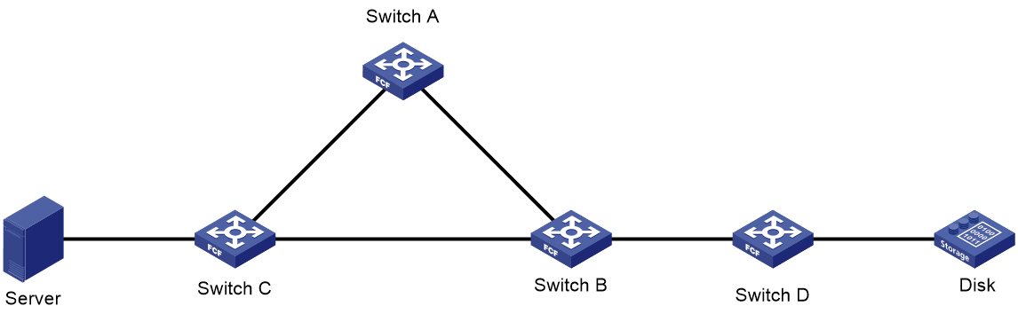
Procedure
|
|
IMPORTANT: By default, interfaces on the device are disabled (in ADM or Administratively Down state). To have an interface operate, you must use the undo shutdown command to enable that interface. |
This section describes only FCS configurations.
# Configure the switch to operate in advanced mode, save the configuration, and reboot the switch. (Skip this step if the switch is operating in advanced mode.)
<SwitchA> system-view
[SwitchA] system-working-mode advance
[SwitchA] save
[SwitchA] quit
<SwitchA> reboot
# Configure the switch to operate in FCF mode.
<SwitchA> system-view
[SwitchA] fcoe-mode fcf
# Start a topology discovery in VSAN 1.
[SwitchA] fcs discovery start vsan 1
Verifying the configuration
# Display the FCS database information in VSAN 1 on Switch A.
[SwitchA] display fcs database vsan 1
FCS Local Database in VSAN 1:
IE WWN : 10:00:00:11:22:00:01:01
Domain ID : 0x01
Management address list : snmp://192.168.0.1
Fabric name : 10:00:00:11:22:00:01:01
Logical name : SwitchA
Information list : H3C#H3C Simware32#Version 7.1.036, Alpha 0101
IE_Ports:
Interface Port WWN Port type Attached port WWNs
Vfc1 e1:01:00:11:22:00:01:01 E_Port e2:01:00:11:22:00:01:01
Vfc2 e1:01:00:11:22:00:01:02 E_Port e3:01:00:11:22:00:01:01
IE WWN : 10:00:00:11:22:00:01:02
Domain ID : 0x02
Management address list : snmp://192.168.0.2
Fabric name : 10:00:00:11:22:00:01:01
Logical name : SwitchB
Information list : H3C#H3C Simware32#Version 7.1.036, Alpha 0101
IE_Ports:
Interface Port WWN Port type Attached port WWNs
- e2:01:00:11:22:00:01:01 E_Port e1:01:00:11:22:00:01:01
- e2:01:00:11:22:00:01:02 E_Port e3:01:00:11:22:00:01:02
- e2:01:00:11:22:00:01:03 E_Port e4:01:00:11:22:00:01:01
IE WWN : 10:00:00:11:22:00:01:03
Domain ID : 0x03
Management address list : snmp://192.168.0.3
Fabric name : 10:00:00:11:22:00:01:01
Logical name : SwitchC
Information list : H3C#H3C Simware32#Version 7.1.036, Alpha 0101
IE_Ports:
Interface Port WWN Port type Attached port WWNs
- e3:01:00:11:22:00:01:01 E_Port e1:01:00:11:22:00:01:02
- e3:01:00:11:22:00:01:02 E_Port e2:01:00:11:22:00:01:02
- e3:01:00:11:22:00:01:03 F_Port 48:33:43:2d:46:43:1A:1A
IE WWN : 10:00:00:11:22:00:01:04
Domain ID : 0x04
Management address list : snmp://192.168.0.4
Fabric name : 10:00:00:11:22:00:01:01
Logical name : SwitchD
Information list : H3C#H3C Simware32#Version 7.1.036, Alpha 0101
IE_Ports:
Interface Port WWN Port type Attached port WWNs
- e4:01:00:11:22:00:01:01 E_Port e2:01:00:11:22:00:01:03
- e4:01:00:11:22:00:01:02 F_Port 48:33:43:2d:46:43:1B:1B
# Display brief information about IEs in VSAN 1 on Switch A.
[SwitchA] display fcs ie vsan 1
IE List for VSAN 1:
IE WWN Domain ID Mgmt addr list Logical name
10:00:00:11:22:00:01:01 0x01 snmp://192.168.0.1 SwitchA
10:00:00:11:22:00:01:02 0x02 snmp://192.168.0.2 SwitchB
10:00:00:11:22:00:01:03 0x03 snmp://192.168.0.3 SwitchC
10:00:00:11:22:00:01:04 0x04 snmp://192.168.0.4 SwitchD
Total 4 IEs in Fabric.
# Display brief information about ports in VSAN 1 on Switch A.
[SwitchA] display fcs port vsan 1
Port List for VSAN 1:
IE WWN: 10:00:00:11:22:00:01:01
Port WWN Port type Tx type Module type
e1:01:00:11:22:00:01:01 E_Port 10GBASE-CX4 SFP with serial ID
e1:01:00:11:22:00:01:02 E_Port 10GBASE-CX4 SFP with serial ID
Total 2 switch-ports in IE.
IE WWN: 10:00:00:11:22:00:01:02
Port WWN Port type Tx type Module type
e2:01:00:11:22:00:01:01 E_Port 10GBASE-CX4 SFP with serial ID
e2:01:00:11:22:00:01:02 E_Port 10GBASE-CX4 SFP with serial ID
e2:01:00:11:22:00:01:03 E_Port 10GBASE-CX4 SFP with serial ID
Total 3 switch-ports in IE.
IE WWN: 10:00:00:11:22:00:01:03
Port WWN Port type Tx type Module type
e3:01:00:11:22:00:01:01 E_Port 10GBASE-CX4 SFP with serial ID
e3:01:00:11:22:00:01:02 E_Port 10GBASE-CX4 SFP with serial ID
e3:01:00:11:22:00:01:03 F_Port 10GBASE-CX4 SFP with serial ID
Total 3 switch-ports in IE.
IE WWN: 10:00:00:11:22:00:01:04
Port WWN Port type Tx type Module type
e4:01:00:11:22:00:01:01 E_Port 10GBASE-CX4 SFP with serial ID
e4:01:00:11:22:00:01:02 F_Port 10GBASE-CX4 SFP with serial ID
Total 2 switch-ports in IE.
Configuring FDMI
About FDMI
The Fabric Device Management Interface (FDMI) feature allows you to view information about host bus adapters (HBAs) on all registered nodes in a fabric. The HBA information includes HBAs and ports on each HBA.
Each switch obtains the HBA information of its directly connected and registered nodes and sends the information to other switches in the fabric. As a result, each switch has HBA information for all the nodes registered with the fabric.
HBA object attributes
An HBA is an FC storage network card. Each HBA appears as an HBA object to the switch. An HBA object has a set of attributes, as shown in Table 9.
|
Attribute |
Description |
|
HBA ID |
An HBA ID identifies an HBA. If an HBA has only one physical interface, the WWN of the physical interface is used as the HBA ID. If the HBA has more than one physical interface, the WWN of one of the physical interfaces is selected as the HBA ID. |
|
Manufacturer |
Manufacturer of the HBA. |
|
Serial Number |
Serial number of the HBA. |
|
Model |
Model of the HBA. |
|
Model Description |
Model description for the HBA. |
|
Node Name |
WWN of the node where the HBA resides. |
|
Node Symbolic Name |
Symbolic name of the node where the HBA resides. |
|
Hardware Version |
Hardware version of the HBA. |
|
Driver Version |
Driver version of the HBA. |
|
Option ROM Version |
ROM version of the HBA. |
|
Firmware Version |
Firmware version of the HBA. |
|
OS Name and Version |
Operating system name and version number of the HBA. |
|
Maximum CT Payload |
Maximum length of CT payload allowed by the HBA. The CT payload includes the basic header and extended header of CT packets, but not the FC header. |
|
Vendor Identifier |
T10 code of the manufacturer or OEM for the HBA. |
|
Vendor Specific Information |
Vendor-defined information, which is hexadecimal. |
|
Number of Ports |
Number of ports on the HBA. |
|
Fabric Name |
Name of the fabric where the HBA resides. |
|
Boot BIOS Version |
Boot BIOS version of the HBA. |
|
Boot BIOS State |
Boot BIOS state for the HBA: Enabled or Disabled. |
Port object attributes
Each physical FC interface on an HBA object is a port object. An HBA object can have a maximum of 256 port objects. A port object has a set of attributes, as shown in Table 10.
When RPRT or RPA packets from a port object include Smart SAN attributes, the following rules apply to displaying FDMI database information:
· If the switch is enabled with Smart SAN, Smart SAN attributes are displayed for the port object.
· If the switch is not enabled with Smart SAN, no information is displayed.
When RPRT or RPA packets from a port object do not include Smart SAN attributes, Smart SAN attributes are not displayed, regardless of whether the switch is enabled with Smart SAN.
The following are Smart SAN attributes:
· Smart SAN Service Category.
· Smart SAN globally unique identifier (GUID).
· Smart SAN Version.
· Smart SAN Product Name (Model).
· Smart SAN Port Info.
· Smart SAN QoS Support.
· Smart SAN Security Support.
· Smart SAN Connected Ports.
Table 10 Port object attributes
|
Field |
Description |
|
Port Name |
WWN of the port. |
|
Port Symbolic Name |
Symbolic name of the port. |
|
Port Identifier |
FC address of the port. |
|
Port Type |
Port type. |
|
Supported Class of Service |
Class of service supported by the port: Class 2 or Class 3. |
|
Supported FC-4 Types |
FC-4 types supported by the port: · FCP. · GS3. · IP. · LLC/SNAP. · NPV. · NVMeoFC. · SNMP. · SW-ILS. · VI. |
|
Port Active FC-4 Types |
FC-4 types active on the port, which can be one or more of the following options: · FCP. · GS3. · IP. · LLC/SNAP. · NPV. · NVMeoFC. · SNMP. · SW-ILS. · VI. |
|
Supported Speed |
Speeds supported by the port: · 1 Gbps. · 2 Gbps. · 4 Gbps. · 8 Gbps. · 10 Gbps. · 16 Gbps. · 20 Gbps. · 32 Gbps. · 40 Gbps. This field displays Unknown for speeds other than the preceding ones. This field displays Speed not obtained when the supported speeds cannot be determined. |
|
Current Speed |
The current speed can only be one of the following options: · 1 Gbps. · 2 Gbps. · 4 Gbps. · 8 Gbps. · 10 Gbps. · 16 Gbps. · 20 Gbps. · 32 Gbps. · 40 Gbps. This field displays Unknown for speeds other than the preceding ones. This field displays Speed not obtained when the current speed cannot be determined. |
|
OS Device Name |
Operating system name for the port. |
|
Maximum Frame Size |
Maximum frame size supported by the port. |
|
Host Name |
Name of the node where the port resides. |
|
Node Name |
WWN of the node where the port resides. |
|
Port Fabric Name |
Name of the fabric where the port resides. |
|
Port State |
Current state of the port. |
|
Number of Discovered Ports |
Number of ports discovered by the port. |
|
Smart SAN Service Category |
Smart SAN service category: Smart SAN Initiator or Smart SAN Target. |
|
Smart SAN GUID |
Smart SAN GUID. |
|
Smart SAN Version |
Smart SAN version. |
|
Smart SAN Product Name (Model) |
Smart SAN product name (model). |
|
Smart SAN Port Info |
Port information: · 0x01 (Physical)—The port is a physical port. · 0x02 (NPIV)—The port supports NPIV. · 0x03 (SRIOV)—The port supports SRIOV. |
|
Smart SAN QoS Support |
QoS support of the port: 0x00 (Not supported) and 0x01 (Supported). |
|
Smart SAN Security Support |
Security types supported by the port: · 0x00 (Not Supported). · 0x01 (Tier-1). · 0x02 (Tier-2). · 0x03 (Tier-3). |
|
Smart SAN Connected Ports |
This field displays ports on remote nodes discovered by the port. |
Display and maintenance commands for FDMI
Execute display commands in any view.
|
Task |
Command |
|
Display the FDMI database information. |
display fdmi database [ vsan vsan-id ] [ hba-id hba-id ] [ verbose ] |
Configuring FC ping
About FC ping
In an FC SAN, use the fcping command to identify whether a destination address is reachable and to test network connectivity.
In an FC ping operation, the source device sends echo requests to the destination device. It determines whether the destination is reachable based on whether it receives echo replies. If the destination is reachable, the source device can perform the following operations:
· Determine the link quality based on the number of echo requests sent and the number of replies received.
· Determine the distance between the source and destination based on the round-trip time of FC ping packets.
A switch supports the following FC ping destinations:
· N_Port—Use the fcping command on the switch to ping an N_Port at the remote end. The destination address of the FC ping operation is the FC address of the N_Port.
· Switch—The destination address is the destination switch's domain controller address FFFCxx (xx is the domain ID of the destination switch).
Procedure
Execute the following command in any view to identify whether a destination address is reachable:
fcping [ -c count | -t timeout ] * fcid fcid vsan vsan-id
To abort the FC ping operation during the execution of this command, press Ctrl+C.
FC ping configuration examples
Example: Configuring FC ping by using FC interfaces
Network configuration
As shown in Figure 42, identify whether Switch A and Switch B can reach each other.
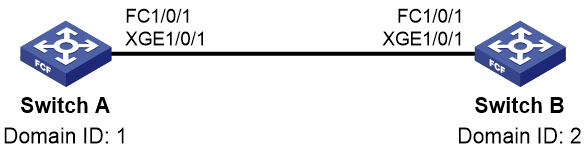
Procedure
|
|
IMPORTANT: By default, interfaces on the device are disabled (in ADM or Administratively Down state). To have an interface operate, you must use the undo shutdown command to enable that interface. |
1. Configure Switch A:
# Configure the switch to operate in advanced mode, save the configuration, and reboot the switch. (Skip this step if the switch is operating in advanced mode.)
<SwitchA> system-view
[SwitchA] system-working-mode advance
[SwitchA] save
[SwitchA] quit
<SwitchA> reboot
# Configure the switch to operate in FCF mode.
<SwitchA> system-view
[SwitchA] fcoe-mode fcf
# Enable the fabric configuration feature for VSAN 1.
[SwitchA] vsan 1
[SwitchA-vsan1] domain configure enable
# Set the domain ID to 1.
[SwitchA-vsan1] domain-id 1 static
Nondisruptive reconfiguration might be performed or the switch might be isolated. Continue? [Y/N]:y
[SwitchA-vsan1] quit
# Change FortyGigE 1/0/1 into FC 1/0/1.
[SwitchA] interface fortygige 1/0/1
[SwitchA-FortyGigE1/0/1] port-type fc
# Configure the mode of FC 1/0/1 as E.
[SwitchA-Fc1/0/1] fc mode e
# Configure FC 1/0/1 to autonegotiate the speed.
[SwitchA-Fc1/0/1] speed auto
# Configure the trunk mode of FC 1/0/1 as On, and assign FC 1/0/1 to VSAN 1 as a trunk port.
[SwitchA-Fc1/0/1] port trunk mode on
[SwitchA-Fc1/0/1] port trunk vsan 1
[SwitchA-Fc1/0/1] quit
# Enable FC and FCoE in VLAN 10 and map VLAN 10 to VSAN 1.
[SwitchA] vlan 10
[SwitchA-vlan10] fcoe enable vsan 1
[SwitchA-vlan10] quit
# Configure a static route on Switch A.
[SwitchA] vsan 1
[SwitchA-vsan1] fc route-static 020000 8 fc 1/0/1
2. Configure Switch B:
# Configure the switch to operate in advanced mode, save the configuration, and reboot the switch. (Skip this step if the switch is operating in advanced mode.)
<SwitchB> system-view
[SwitchB] system-working-mode advance
[SwitchB] save
[SwitchB] quit
<SwitchB> reboot
# Configure the switch to operate in FCF mode.
<SwitchB> system-view
[SwitchB] fcoe-mode fcf
# Enable the fabric configuration feature for VSAN 1.
[SwitchB] vsan 1
[SwitchB-vsan1] domain configure enable
# Set the domain ID to 2.
[SwitchB-vsan1] domain-id 2 static
Nondisruptive reconfiguration might be performed or the switch might be isolated. Continue? [Y/N]:y
[SwitchB-vsan1] quit
# Change FortyGigE 1/0/1 into FC 1/0/1.
[SwitchB] interface fortygige 1/0/1
[SwitchB-FortyGigE1/0/1] port-type fc
# Configure the mode of FC 1/0/1 as E.
[SwitchB-Fc1/0/1] fc mode e
# Configure FC 1/0/1 to autonegotiate the speed.
[SwitchB-Fc1/0/1] speed auto
# Configure the trunk mode of FC 1/0/1 as On, and assign FC 1/0/1 to VSAN 1 as a trunk port.
[SwitchB-Fc1/0/1] port trunk mode on
[SwitchB-Fc1/0/1] port trunk vsan 1
[SwitchB-Fc1/0/1] quit
# Enable FC and FCoE in VLAN 10 and map VLAN 10 to VSAN 1.
[SwitchB] vlan 10
[SwitchB-vlan10] fcoe enable vsan 1
[SwitchB-vlan10] quit
# Configure a static route on Switch B.
[SwitchB] vsan 1
[SwitchB-vsan1] fc route-static 010000 8 fc 1/0/1
Verifying the configuration
# FCping a switch from another switch, for example, FCping Switch B from Switch A.
[SwitchA-vsan1] fcping fcid fffc02 vsan 1
FCPING fcid 0xfffc02: 128 data bytes, press CTRL+C to break.
Reply from 0xfffc02: bytes = 128 time = 23 ms
Reply from 0xfffc02: bytes = 128 time = 9 ms
Reply from 0xfffc02: bytes = 128 time = 19 ms
Reply from 0xfffc02: bytes = 128 time = 14 ms
Reply from 0xfffc02: bytes = 128 time = 25 ms
--- 0xfffc02 fcping statistics ---
5 packet(s) transmitted
5 packet(s) received
0.00% packet loss
round-trip min/avg/max = 9/18/25 ms
Example: Configuring FC ping by using VFC interfaces
Network configuration
Identify whether Switch A and Switch B can reach each other.
Figure 43 Network diagram

Procedure
|
|
IMPORTANT: By default, interfaces on the device are disabled (in ADM or Administratively Down state). To have an interface operate, you must use the undo shutdown command to enable that interface. |
1. Configure Switch A:
# Configure the switch to operate in advanced mode, save the configuration, and reboot the switch. (Skip this step if the switch is operating in advanced mode.)
<SwitchA> system-view
[SwitchA] system-working-mode advance
[SwitchA] save
[SwitchA] quit
<SwitchA> reboot
# Configure the switch to operate in FCF mode.
<SwitchA> system-view
[SwitchA] fcoe-mode fcf
# Enable the fabric configuration feature for VSAN 1.
[SwitchA] vsan 1
[SwitchA-vsan1] domain configure enable
# Set the domain ID to 1.
[SwitchA-vsan1] domain-id 1 static
Nondisruptive reconfiguration might be performed or the switch might be isolated. Continue? [Y/N]:y
[SwitchA-vsan1] quit
# Create VFC 1.
[SwitchA] interface vfc 1
# Configure the mode of VFC 1 as E.
[SwitchA-Vfc1] fc mode e
# Bind VFC 1 to FortyGigE 1/0/1.
[SwitchA-Vfc1] bind interface fortygige 1/0/1
# Assign VFC 1 to VSAN 1 as a trunk port.
[SwitchA-Vfc1] port trunk vsan 1
[SwitchA-Vfc1] quit
# Configure FortyGigE 1/0/1 as a trunk port, and assign the port to VLAN 10.
[SwitchA] interface fortygige 1/0/1
[SwitchA-FortyGigE1/0/1] port link-type trunk
[SwitchA-FortyGigE1/0/1] port trunk permit vlan 10
[SwitchA-FortyGigE1/0/1] quit
# Enable FC and FCoE in VLAN 10 and map VLAN 10 to VSAN 1.
[SwitchA] vlan 10
[SwitchA-vlan10] fcoe enable vsan 1
[SwitchA-vlan10] quit
# Configure a static route on Switch A.
[SwitchA] vsan 1
[SwitchA-vsan1] fc route-static 020000 8 vfc 1
[SwitchA-vsan1] quit
2. Configure Switch B:
# Configure the switch to operate in advanced mode, save the configuration, and reboot the switch. (Skip this step if the switch is operating in advanced mode.)
<SwitchB> system-view
[SwitchB] system-working-mode advance
[SwitchB] save
[SwitchB] quit
<SwitchB> reboot
# Configure the switch to operate in FCF mode.
<SwitchB> system-view
[SwitchB] fcoe-mode fcf
# Enable the fabric configuration feature for VSAN 1.
[SwitchB] vsan 1
[SwitchB-vsan1] domain configure enable
# Set the domain ID to 2.
[SwitchB-vsan1] domain-id 2 static
Nondisruptive reconfiguration might be performed or the switch might be isolated. Continue? [Y/N]:y
[SwitchB-vsan1] quit
# Create VFC 1.
[SwitchB] interface vfc 1
# Configure the mode of VFC 1 as E.
[SwitchB-Vfc1] fc mode e
# Bind VFC 1 to FortyGigE 1/0/1.
[SwitchB-Vfc1] bind interface fortygige 1/0/1
# Assign VFC 1 to VSAN 1.
[SwitchB-Vfc1] port trunk vsan 1
[SwitchB-Vfc1] quit
# Configure FortyGigE 1/0/1 as a trunk port, and assign the port to VLAN 10.
[SwitchB] interface fortygige 1/0/1
[SwitchB-FortyGigE1/0/1] port link-type trunk
[SwitchB-FortyGigE1/0/1] port trunk permit vlan 10
[SwitchB-FortyGigE1/0/1] quit
# Enable FC and FCoE in VLAN 10 and map VLAN 10 to VSAN 1.
[SwitchB] vlan 10
[SwitchB-vlan10] fcoe enable vsan 1
[SwitchB-vlan10] quit
# Configure a static route on Switch B.
[SwitchB] vsan 1
[SwitchB-vsan1] fc route-static 010000 8 vfc 1
[SwitchB-vsan1] quit
Verifying the configuration
# FCping a switch from another switch, for example, FCping Switch B from Switch A.
[SwitchA] fcping fcid fffc02 vsan 1
FCPING fcid 0xfffc02: 128 data bytes, press CTRL+C to break.
Reply from 0xfffc02: bytes = 128 time = 23 ms
Reply from 0xfffc02: bytes = 128 time = 9 ms
Reply from 0xfffc02: bytes = 128 time = 19 ms
Reply from 0xfffc02: bytes = 128 time = 14 ms
Reply from 0xfffc02: bytes = 128 time = 25 ms
--- 0xfffc02 fcping statistics ---
5 packet(s) transmitted
5 packet(s) received
0.00% packet loss
round-trip min/avg/max = 9/18/25 ms
Configuring FC tracert
About FC tracert
In an FC SAN, use the fctracert command to obtain bidirectional routing information between source and destination, and check the network connectivity.
You can use this feature to identify failed nodes and test network connectivity.
FC tracert includes the following processes:
· Uplink process—Beginning from the source, each switch along the path sends the Switch Trace Route (STR) packet to its next hop until the STR packet reaches the destination switch. (If the destination of FC tracert is a node, the destination switch refers to the FCF switch directly connected to the node.) Each switch adds its uplink path information (including its WWN and domain ID) to the STR packet. After the STR packet reaches the destination switch, the downlink process starts.
· Downlink process—Beginning from the destination switch, each switch along the path sends the STR packet to its next hop until the STR packet reaches the source switch. Each switch adds its downlink path information (with the same content as the uplink path information) to the STR packet. When the source switch receives the STR packet, the FC tracert process ends. The source outputs information (in the STR packet) about all uplink and downlink switches along the path.
If an FCF switch fails to forward the STR packet, the switch performs the following operations:
· Sets an error reason in the packet.
· Sends the packet (containing information about switches the packet has passed through) directly to the source switch.
Figure 44 shows the FC tracert process.
Figure 44 FC tracert flowchart
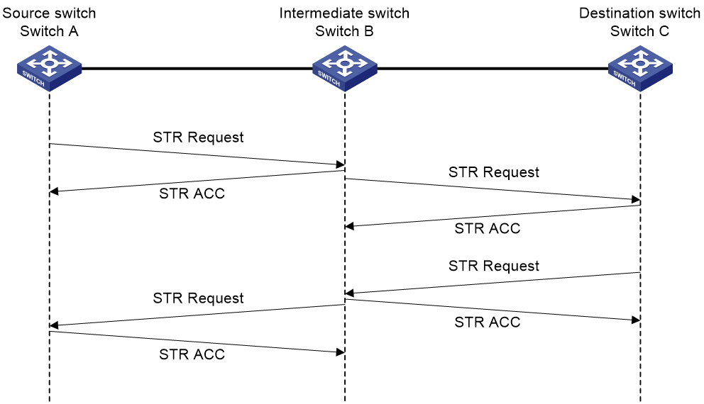
The following describes the process of an FC tracert operation from Switch A to Switch C.
1. Uplink process:
a. Switch A adds its uplink path information (including its WWN and domain ID) to the STR request packet and sends the packet to the next hop Switch B.
b. After receiving the packet, Switch B replies with an STR ACC packet to Switch A.
c. Switch B adds its uplink path information to the received STR packet and sends it to the destination switch, Switch C.
d. After receiving the packet, Switch C replies with an STR ACC packet to Switch B.
e. Switch C adds its uplink path information to the received packet.
The collection of uplink path information is complete.
2. Downlink process:
a. Switch C sends the STR request packet to Switch A hop by hop in the same way as in the uplink process.
b. After receiving the STR request packet with a downlink flag, Switch A outputs information about all uplink and downlink switches.
Procedure
Execute the following command in any view to detect bidirectional routing information between source and destination:
fctracert [ -t timeout ] fcid fcid vsan vsan-id
To abort the FC tracert operation during the execution of this command, press Ctrl+C.
FC tracert configuration examples
Example: Configuring FC tracert by using FC interfaces
Network configuration
As shown in Figure 45, detect bidirectional routing information between Switch A and Switch C, and identify the faulty node (if any).
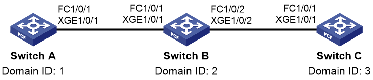
Procedure
|
|
IMPORTANT: By default, interfaces on the device are disabled (in ADM or Administratively Down state). To have an interface operate, you must use the undo shutdown command to enable that interface. |
1. Configure Switch A:
# Configure the switch to operate in advanced mode, save the configuration, and reboot the switch. (Skip this step if the switch is operating in advanced mode.)
<SwitchA> system-view
[SwitchA] system-working-mode advance
[SwitchA] save
[SwitchA] quit
<SwitchA> reboot
# Configure the switch to operate in FCF mode.
<SwitchA> system-view
[SwitchA] fcoe-mode fcf
# Enable the fabric configuration feature for VSAN 1.
[SwitchA] vsan 1
[SwitchA-vsan1] domain configure enable
# Set the domain ID to 1.
[SwitchA-vsan1] domain-id 1 static
Nondisruptive reconfiguration might be performed or the switch might be isolated. Continue? [Y/N]:y
[SwitchA-vsan1] quit
# Change FortyGigE 1/0/1 into FC 1/0/1.
[SwitchA] interface fortygige 1/0/1
[SwitchA-FortyGigE1/0/1] port-type fc
# Configure the mode of FC 1/0/1 as E.
[SwitchA-Fc1/0/1] fc mode e
# Configure FC 1/0/1 to autonegotiate the speed.
[SwitchA-Fc1/0/1] speed auto
# Configure the trunk mode of FC 1/0/1 as On, and assign FC 1/0/1 to VSAN 1 as a trunk port.
[SwitchA-Fc1/0/1] port trunk mode on
[SwitchA-Fc1/0/1] port trunk vsan 1
[SwitchA-Fc1/0/1] quit
# Enable FC and FCoE in VLAN 10 and map VLAN 10 to VSAN 1.
[SwitchA] vlan 10
[SwitchA-vlan10] fcoe enable vsan 1
[SwitchA-vlan10] quit
# Disable FSPF for VSAN 1.
[SwitchA] vsan 1
[SwitchA-vsan1] undo fspf enable
# Configure static routes.
[SwitchA-vsan1] fc route-static 020000 8 fc 1/0/1
[SwitchA-vsan1] fc route-static 030000 8 fc 1/0/1
2. Configure Switch B:
# Configure the switch to operate in advanced mode, save the configuration, and reboot the switch. (Skip this step if the switch is operating in advanced mode.)
<SwitchB> system-view
[SwitchB] system-working-mode advance
[SwitchB] save
[SwitchB] quit
<SwitchB> reboot
# Configure the switch to operate in FCF mode.
<SwitchB> system-view
[SwitchB] fcoe-mode fcf
# Enable the fabric configuration feature for VSAN 1.
[SwitchB] vsan 1
[SwitchB-vsan1] domain configure enable
# Set the domain ID to 2.
[SwitchB-vsan1] domain-id 2 static
Nondisruptive reconfiguration might be performed or the switch might be isolated. Continue? [Y/N]:y
[SwitchB-vsan1] quit
# Change FortyGigE 1/0/1 into FC 1/0/1.
[SwitchB] interface fortygige 1/0/1
[SwitchB-FortyGigE1/0/1] port-type fc
# Configure the mode of FC 1/0/1 as E.
[SwitchB-Fc1/0/1] fc mode e
# Configure FC 1/0/1 to autonegotiate the speed.
[SwitchB-Fc1/0/1] speed auto
# Configure the trunk mode of FC 1/0/1 as On, and assign FC 1/0/1 to VSAN 1 as a trunk port.
[SwitchB-Fc1/0/1] port trunk mode on
[SwitchB-Fc1/0/1] port trunk vsan 1
[SwitchB-Fc1/0/1] quit
# Change FortyGigE 1/0/2 into FC 1/0/2.
[SwitchB] interface fortygige 1/0/2
[SwitchB-FortyGigE1/0/2] port-type fc
# Configure the mode of FC 1/0/2 as E.
[SwitchB-Fc1/0/2] fc mode e
# Configure FC 1/0/2 to autonegotiate the speed.
[SwitchB-Fc1/0/2] speed auto
# Configure the trunk mode of FC 1/0/2 as On, and assign FC 1/0/2 to VSAN 1 as a trunk port.
[SwitchB-Fc1/0/2] port trunk mode on
[SwitchB-Fc1/0/2] port trunk vsan 1
[SwitchB-Fc1/0/2] quit
# Enable FC and FCoE in VLAN 10 and map VLAN 10 to VSAN 1.
[SwitchB] vlan 10
[SwitchB-vlan10] fcoe enable vsan 1
[SwitchB-vlan10] quit
# Disable FSPF for VSAN 1.
[SwitchB] vsan 1
[SwitchB-vsan1] undo fspf enable
# Configure a static route.
[SwitchB-vsan1] fc route-static 010000 8 fc 1/0/1
3. Configure Switch C:
# Configure the switch to operate in advanced mode, save the configuration, and reboot the switch. (Skip this step if the switch is operating in advanced mode.)
<SwitchC> system-view
[SwitchC] system-working-mode advance
[SwitchC] save
[SwitchC] quit
<SwitchC> reboot
# Configure the switch to operate in FCF mode.
<SwitchC> system-view
[SwitchC] fcoe-mode fcf
# Enable the fabric configuration feature for VSAN 1.
[SwitchC] vsan 1
[SwitchC-vsan1] domain configure enable
# Set the domain ID to 3.
[SwitchC-vsan1] domain-id 3 static
Nondisruptive reconfiguration might be performed or the switch might be isolated. Continue? [Y/N]:y
[SwitchC-vsan1] quit
# Change FortyGigE 1/0/1 into FC 1/0/1.
[SwitchC] interface fortygige 1/0/1
[SwitchC-FortyGigE1/0/1] port-type fc
# Configure the mode of FC 1/0/1 as E.
[SwitchC-Fc1/0/1] fc mode e
# Configure FC 1/0/1 to autonegotiate the speed.
[SwitchC-Fc1/0/1] speed auto
# Configure the trunk mode of FC 1/0/1 as On, and assign FC 1/0/1 to VSAN 1 as a trunk port.
[SwitchC-Fc1/0/1] port trunk mode on
[SwitchC-Fc1/0/1] port trunk vsan 1
[SwitchC-Fc1/0/1] quit
# Enable FC and FCoE in VLAN 10 and map VLAN 10 to VSAN 1.
[SwitchC] vlan 10
[SwitchC-vlan10] fcoe enable vsan 1
[SwitchC-vlan10] quit
# Disable FSPF for VSAN 1.
[SwitchC] vsan 1
[SwitchC-vsan1] undo fspf enable
4. FCping Switch C from Switch A.
[SwitchA-vsan1] fcping fcid fffc03 vsan 1
FCPING fcid 0xfffc03: 128 data bytes, press CTRL+C to break.
Request time out
Request time out
Request time out
Request time out
Request time out
--- 0xfffc03 fcping statistics ---
5 packet(s) transmitted
0 packet(s) received
100.00% packet loss
The output shows that Switch A cannot reach Switch C.
5. Use the fctracert command to identify the faulty node.
[SwitchA-vsan1] fctracert fcid fffc03 vsan 1
Route present for: 0xfffc03, press CTRL+C to break
20:00:00:0b:46:00:02:82(0xfffc01)
20:00:00:05:30:00:18:db(0xfffc02)
Fctracert uncompleted: no route to destination port.
The output shows that:
¡ Switch A can reach Switch B.
¡ Switch B cannot reach Switch C.
Verifying the configuration
# Use the display fc routing-table command on Switch B to verify that a route to Switch C does not exist. (Details not shown.)
Example: Configuring FC tracert by using VFC interfaces
Network configuration
As shown in Figure 46, detect bidirectional routing information between Switch A and Switch C, and identify the faulty node (if any).
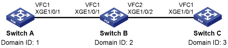
Procedure
|
|
IMPORTANT: By default, interfaces on the device are disabled (in ADM or Administratively Down state). To have an interface operate, you must use the undo shutdown command to enable that interface. |
1. Configure Switch A:
# Configure the switch to operate in advanced mode, save the configuration, and reboot the switch. (Skip this step if the switch is operating in advanced mode.)
<SwitchA> system-view
[SwitchA] system-working-mode advance
[SwitchA] save
[SwitchA] quit
<SwitchA> reboot
# Configure the switch to operate in FCF mode.
<SwitchA> system-view
[SwitchA] fcoe-mode fcf
# Enable the fabric configuration feature for VSAN 1.
[SwitchA] vsan 1
[SwitchA-vsan1] domain configure enable
# Set the domain ID to 1.
[SwitchA-vsan1] domain-id 1 static
Nondisruptive reconfiguration might be performed or the switch might be isolated. Continue? [Y/N]:y
# Disable FSPF for VSAN 1.
[SwitchA-vsan1] undo fspf enable
# Configure static routes.
[SwitchA-vsan1] fc route-static 020000 8 vfc 1
[SwitchA-vsan1] fc route-static 030000 8 vfc 1
[SwitchA-vsan1] quit
# Create VFC 1.
[SwitchA] interface vfc 1
# Configure the mode of VFC 1 as E.
[SwitchA-Vfc1] fc mode e
# Bind VFC 1 to FortyGigE 1/0/1.
[SwitchA-Vfc1] bind interface fortygige 1/0/1
# Assign VFC 1 to VSAN 1 as a trunk port.
[SwitchA-Vfc1] port trunk vsan 1
[SwitchA-Vfc1] quit
# Configure FortyGigE 1/0/1 as a trunk port, and assign the port to VLAN 10.
[SwitchA] interface fortygige 1/0/1
[SwitchA-FortyGigE1/0/1] port link-type trunk
[SwitchA-FortyGigE1/0/1] port trunk permit vlan 10
[SwitchA-FortyGigE1/0/1] quit
# Enable FC and FCoE in VLAN 10 and map VLAN 10 to VSAN 1.
[SwitchA] vlan 10
[SwitchA-vlan10] fcoe enable vsan 1
[SwitchA-vlan10] quit
2. Configure Switch B:
# Configure the switch to operate in advanced mode, save the configuration, and reboot the switch. (Skip this step if the switch is operating in advanced mode.)
<SwitchB> system-view
[SwitchB] system-working-mode advance
[SwitchB] save
[SwitchB] quit
<SwitchB> reboot
# Configure the switch to operate in FCF mode.
<SwitchB> system-view
[SwitchB] fcoe-mode fcf
# Enable the fabric configuration feature for VSAN 1.
[SwitchB] vsan 1
[SwitchB-vsan1] domain configure enable
# Set the domain ID to 2.
[SwitchB-vsan1] domain-id 2 static
Nondisruptive reconfiguration might be performed or the switch might be isolated. Continue? [Y/N]:y
# Disable FSPF for VSAN 1.
[SwitchB-vsan1] undo fspf enable
# Configure a static route.
[SwitchB-vsan1] fc route-static 010000 8 vfc 1
[SwitchB-vsan1] quit
# Create VFC 1.
[SwitchB] interface vfc 1
# Configure the mode of VFC 1 as E.
[SwitchB-Vfc1] fc mode e
# Bind VFC 1 to FortyGigE 1/0/1.
[SwitchB-Vfc1] bind interface fortygige 1/0/1
# Assign VFC 1 to VSAN 1 as a trunk port.
[SwitchB-Vfc1] port trunk vsan 1
[SwitchB-Vfc1] quit
# Configure FortyGigE 1/0/1 as a trunk port, and assign the port to VLAN 10.
[SwitchB] interface fortygige 1/0/1
[SwitchB-FortyGigE1/0/1] port link-type trunk
[SwitchB-FortyGigE1/0/1] port trunk permit vlan 10
[SwitchB-FortyGigE1/0/1] quit
# Create VFC 2.
[SwitchB] interface vfc 2
# Configure the mode of VFC 2 as E.
[SwitchB-Vfc2] fc mode e
# Bind VFC 2 to FortyGigE 1/0/2.
[SwitchB-Vfc2] bind interface fortygige 1/0/2
# Assign VFC 2 to VSAN 1 as a trunk port.
[SwitchB-Vfc2] port trunk vsan 1
[SwitchB-Vfc2] quit
# Configure FortyGigE 1/0/2 as a trunk port, and assign the port to VLAN 10.
[SwitchB] interface fortygige 1/0/2
[SwitchB-FortyGigE1/0/2] port link-type trunk
[SwitchB-FortyGigE1/0/2] port trunk permit vlan 10
[SwitchB-FortyGigE1/0/2] quit
# Enable FC and FCoE in VLAN 10 and map VLAN 10 to VSAN 1.
[SwitchB] vlan 10
[SwitchB-vlan10] fcoe enable vsan 1
[SwitchB-vlan10] quit
3. Configure Switch C:
# Configure the switch to operate in advanced mode, save the configuration, and reboot the switch. (Skip this step if the switch is operating in advanced mode.)
<SwitchC> system-view
[SwitchC] system-working-mode advance
[SwitchC] save
[SwitchC] quit
<SwitchC> reboot
# Configure the switch to operate in FCF mode.
<SwitchC> system-view
[SwitchC] fcoe-mode fcf
# Enable the fabric configuration feature for VSAN 1.
[SwitchC] vsan 1
[SwitchC-vsan1] domain configure enable
# Set the domain ID to 3.
[SwitchC-vsan1] domain-id 3 static
Nondisruptive reconfiguration might be performed or the switch might be isolated. Continue? [Y/N]:y
# Disable FSPF for VSAN 1.
[SwitchC-vsan1] undo fspf enable
[SwitchC-vsan1] quit
# Create VFC 1.
[SwitchC] interface vfc 1
# Configure the mode of VFC 1 as E.
[SwitchC-Vfc1] fc mode e
# Bind VFC 1 to FortyGigE 1/0/1.
[SwitchC-Vfc1] bind interface fortygige 1/0/1
# Assign VFC 1 to VSAN 1 as a trunk port.
[SwitchC-Vfc1] port trunk vsan 1
[SwitchC-Vfc1] quit
# Configure FortyGigE 1/0/1 as a trunk port, and assign the port to VLAN 10.
[SwitchC] interface fortygige 1/0/1
[SwitchC-FortyGigE1/0/1] port link-type trunk
[SwitchC-FortyGigE1/0/1] port trunk permit vlan 10
[SwitchC-FortyGigE1/0/1] quit
# Enable FC and FCoE in VLAN 10 and map VLAN 10 to VSAN 1.
[SwitchC] vlan 10
[SwitchC-vlan10] fcoe enable vsan 1
[SwitchC-vlan10] quit
4. FCping Switch C from Switch A.
[SwitchA] fcping fcid fffc03 vsan 1
FCPING fcid 0xfffc03: 128 data bytes, press CTRL+C to break.
Request time out
Request time out
Request time out
Request time out
Request time out
--- 0xfffc03 fcping statistics ---
5 packet(s) transmitted
0 packet(s) received
100.00% packet loss
The output shows that Switch A cannot reach Switch C.
5. Use the fctracert command to identify the faulty node.
[SwitchA] fctracert fcid fffc03 vsan 1
Route present for: 0xfffc03, press CTRL+C to break
20:00:00:0b:46:00:02:82(0xfffc01)
20:00:00:05:30:00:18:db(0xfffc02)
Fctracert uncompleted: no route to destination port.
The output shows that:
¡ Switch A can reach Switch B.
¡ Switch B cannot reach Switch C.
Verifying the configuration
# Use the display fc routing-table command on Switch B to verify that a route to Switch C does not exist. (Details not shown.)
Comprehensive FC and FCoE configuration examples
Example: Configuring FCoE by using VFC interfaces
Network configuration
As shown in Figure 47:
· Switch A and Switch B are connected to an Ethernet switch, and operate at the access layer of the LAN.
· Switch A and Switch B are connected to Switch C and Switch D, respectively.
· The four switches operate as the FCF switches of the SANs.
Configure FCoE to meet the following requirements:
· The transmission network formed by Switch A, Switch B, and the Ethernet switch can use the server to provide services for the LAN. The transmission network formed by switches A through D can enable the server to access the disk device.
· Link backup is used to implement high availability for the packets to and from the server and disk device.
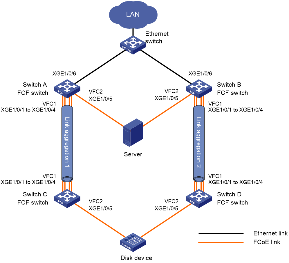
Requirements analysis
As a best practice to transmit the storage traffic over lossless Ethernet links in the SANs, perform the following tasks:
· Configure DCBX, PFC in auto mode, and ETS on the Ethernet interfaces connecting the switches to the server.
· Configure DCBX and PFC in auto mode on the Ethernet interfaces connecting the switches to the disk device.
· Enable PFC by force on the Ethernet interfaces connecting switches.
To implement link backup between the server and the disk device, use two separate SANs to provide connections between the server and the disk device. The two SANs can use the same VSAN. The two separate VSANs are as follows:
· One physical SAN is formed by the server, Switch A, Switch C, and the disk device.
· The other physical SAN is formed by the server, Switch B, Switch D, and the disk device.
To transmit the Ethernet traffic of the LAN in VLAN 1001, configure the following interfaces to allow VLAN 1001:
· The Ethernet interfaces connecting Switch A and Switch B to the LAN.
· The Ethernet interfaces connecting Switch A and Switch B to the server.
To transmit the storage traffic of the SANs in VSAN 100, configure the interfaces connecting the four FCF switches to the SANs to allow VSAN 100.
To transmit the storage traffic of VSAN 100 within VLAN 4001, map VLAN 4001 to VSAN 100.
To avoid physical loops in a complex LAN, enable STP on the Ethernet interfaces connecting Switch A and Switch B to the LAN. In this example, you do not need to enable STP, because the LAN is simple and will not have loops.
To prevent loops on the interfaces that connect Switch A and Switch B to the server, configure the interfaces as edge ports and enable BPDU guard. An edge port does not participate in spanning tree calculation and can rapidly transition to the forwarding state. When the server logs in to Switch A or Switch B again, traffic loss is minimized for the server.
To prevent STP from blocking the interfaces that are responsible for forwarding storage traffic on Switch A and Switch B, disable STP on the interfaces connecting the four FCF switches.
For the server to access the resources in the disk device, configure the members in the default zone to access each other.
To increase the bandwidth for the link between Switch A and Switch C and implement link backup and load sharing, configure Ethernet link aggregation group 1.
To increase the bandwidth for the link between Switch B and Switch D and implement link backup and load sharing, configure Ethernet link aggregation group 2.
Restrictions and guidelines
As a best practice, build the fabric dynamically and use FSPF for FC routing when the SANs are complex.
Configuring Switch A
1. Configure the switch to operate in advanced mode, save the configuration, and reboot the switch. (Skip this step if the switch is operating in advanced mode.)
<SwitchA> system-view
[SwitchA] system-working-mode advance
[SwitchA] save
[SwitchA] quit
<SwitchA> reboot
2. Configure VLANs and interfaces:
# Create VLANs 1001 and 4001, which are intended to transmit Ethernet traffic and storage traffic, respectively.
<SwitchA> system-view
[SwitchA] vlan 1001
[SwitchA-vlan1001] description ToLAN
[SwitchA-vlan1001] quit
[SwitchA] vlan 4001
[SwitchA-vlan4001] description ToSAN
[SwitchA-vlan4001] quit
# Enable STP globally.
[SwitchA] stp global enable
# Enable BPDU guard globally.
[SwitchA] stp bpdu-protection
# Configure FortyGigE 1/0/5 as a hybrid port.
[SwitchA] interface fortygige 1/0/5
[SwitchA-FortyGigE1/0/5] port link-type hybrid
# Assign FortyGigE 1/0/5 to VLAN 1001 as an untagged member.
[SwitchA-FortyGigE1/0/5] port hybrid vlan 1001 untagged
# Assign FortyGigE 1/0/5 to VLAN 4001 as a tagged member.
[SwitchA-FortyGigE1/0/5] port hybrid vlan 4001 tagged
# Set the PVID to VLAN 1001 for the interface.
[SwitchA-FortyGigE1/0/5] port hybrid pvid vlan 1001
# Disable STP on FortyGigE 1/0/5.
[SwitchA-FortyGigE1/0/5] undo stp enable
# Configure FortyGigE 1/0/5 as an edge port.
[SwitchA-FortyGigE1/0/5] stp edged-port
# Enable BPDU guard on FortyGigE 1/0/5.
[SwitchA-FortyGigE1/0/5] stp port bpdu-protection enable
[SwitchA-FortyGigE1/0/5] quit
# Configure FortyGigE 1/0/6 as a trunk port, and assign the interface to VLAN 1001.
[SwitchA] interface fortygige 1/0/6
[SwitchA-FortyGigE1/0/6] port link-type trunk
[SwitchA-FortyGigE1/0/6] port trunk permit vlan 1001
# Enable STP on FortyGigE 1/0/6.
[SwitchA-FortyGigE1/0/6] stp enable
[SwitchA-FortyGigE1/0/6] quit
# Create Layer 2 aggregate interface 1, and configure it to operate in dynamic aggregation mode.
[SwitchA] interface bridge-aggregation 1
[SwitchA-Bridge-Aggregation1] link-aggregation mode dynamic
# Disable STP on Layer 2 aggregate interface 1.
[SwitchA-Bridge-Aggregation1] undo stp enable
[SwitchA-Bridge-Aggregation1] quit
# Assign FortyGigE 1/0/1 through FortyGigE 1/0/4 to Layer 2 aggregation group 1.
[SwitchA] interface fortygige 1/0/1
[SwitchA-FortyGigE1/0/1] port link-aggregation group 1
[SwitchA-FortyGigE1/0/1] quit
[SwitchA] interface fortygige 1/0/2
[SwitchA-FortyGigE1/0/2] port link-aggregation group 1
[SwitchA-FortyGigE1/0/2] quit
[SwitchA] interface fortygige 1/0/3
[SwitchA-FortyGigE1/0/3] port link-aggregation group 1
[SwitchA-FortyGigE1/0/3] quit
[SwitchA] interface fortygige 1/0/4
[SwitchA-FortyGigE1/0/4] port link-aggregation group 1
[SwitchA-FortyGigE1/0/4] quit
# Configure Layer 2 aggregate interface 1 as a trunk port, and assign the aggregate interface to VLAN 4001.
[SwitchA] interface bridge-aggregation 1
[SwitchA-Bridge-Aggregation1] port link-type trunk
[SwitchA-Bridge-Aggregation1] port trunk permit vlan 4001
[SwitchA-Bridge-Aggregation1] quit
3. Configure DCBX:
# Enable LLDP globally.
[SwitchA] lldp global enable
# Create a Layer 2 ACL named DCBX.
[SwitchA] acl mac name DCBX
# Configure the ACL to permit FCoE packets (protocol number is 0x8906) to pass through.
[SwitchA-acl-mac-DCBX] rule 0 permit type 8906 ffff
# Configure the ACL to permit FIP protocol packets (protocol number is 0x8914) to pass through.
[SwitchA-acl-mac-DCBX] rule 5 permit type 8914 ffff
[SwitchA-acl-mac-DCBX] quit
# Create a class named DCBX, configure the operator of the class as OR, and use ACL DCBX as the match criterion of the class.
[SwitchA] traffic classifier DCBX operator or
[SwitchA-classifier-DCBX] if-match acl mac name DCBX
[SwitchA-classifier-DCBX] quit
# Create a behavior named DCBX, and configure the behavior to mark packets with 802.1p priority value 3.
[SwitchA] traffic behavior DCBX
[SwitchA-behavior-DCBX] remark dot1p 3
[SwitchA-behavior-DCBX] quit
# Create a QoS policy named DCBX, associate class DCBX with traffic behavior DCBX in the QoS policy, and specify that the association apply to DCBX.
[SwitchA] qos policy DCBX
[SwitchA-qospolicy-DCBX] classifier DCBX behavior DCBX mode dcbx
[SwitchA-qospolicy-DCBX] quit
# Enable LLDP and DCBX TLV advertising on FortyGigE 1/0/5.
[SwitchA] interface fortygige 1/0/5
[SwitchA-FortyGigE1/0/5] lldp enable
[SwitchA-FortyGigE1/0/5] lldp tlv-enable dot1-tlv dcbx
# Apply QoS policy DCBX to the outgoing traffic of FortyGigE 1/0/5.
[SwitchA-FortyGigE1/0/5] qos apply policy DCBX outbound
4. Configure PFC:
# Enable PFC in auto mode on FortyGigE 1/0/5.
[SwitchA-FortyGigE1/0/5] priority-flow-control auto
# Enable PFC for 802.1p priority 3 on FortyGigE 1/0/5.
[SwitchA-FortyGigE1/0/5] priority-flow-control no-drop dot1p 3
# Configure FortyGigE 1/0/5 to trust the 802.1p priority carried in incoming packets.
[SwitchA-FortyGigE1/0/5] qos trust dot1p
[SwitchA-FortyGigE1/0/5] quit
# Enable PFC by force on FortyGigE 1/0/1.
[SwitchA] interface fortygige 1/0/1
[SwitchA-FortyGigE1/0/1] priority-flow-control enable
# Enable PFC for 802.1p priority 3 on FortyGigE 1/0/1.
[SwitchA-FortyGigE1/0/1] priority-flow-control no-drop dot1p 3
# Configure FortyGigE 1/0/1 to trust the 802.1p priority carried in incoming packets.
[SwitchA-FortyGigE1/0/1] qos trust dot1p
[SwitchA-FortyGigE1/0/1] quit
# Configure interfaces FortyGigE 1/0/2 through FortyGigE 1/0/4 in the same way FortyGigE 1/0/1 is configured.
[SwitchA] interface fortygige 1/0/2
[SwitchA-FortyGigE1/0/2] priority-flow-control enable
[SwitchA-FortyGigE1/0/2] priority-flow-control no-drop dot1p 3
[SwitchA-FortyGigE1/0/2] qos trust dot1p
[SwitchA-FortyGigE1/0/2] quit
[SwitchA] interface fortygige 1/0/3
[SwitchA-FortyGigE1/0/3] priority-flow-control enable
[SwitchA-FortyGigE1/0/3] priority-flow-control no-drop dot1p 3
[SwitchA-FortyGigE1/0/3] qos trust dot1p
[SwitchA-FortyGigE1/0/3] quit
[SwitchA] interface fortygige 1/0/4
[SwitchA-FortyGigE1/0/4] priority-flow-control enable
[SwitchA-FortyGigE1/0/4] priority-flow-control no-drop dot1p 3
[SwitchA-FortyGigE1/0/4] qos trust dot1p
[SwitchA-FortyGigE1/0/4] quit
5. Configure ETS:
# Configure the 802.1p-local priority mapping table to:
¡ Map 802.1p priority value 3 to local precedence 1.
¡ Map the other 802.1p priority values to local precedence 0.
[SwitchA] qos map-table dot1p-lp
[SwitchA-maptbl-dot1p-lp] import 3 export 1
[SwitchA-maptbl-dot1p-lp] import 0 export 0
[SwitchA-maptbl-dot1p-lp] import 1 export 0
[SwitchA-maptbl-dot1p-lp] import 2 export 0
[SwitchA-maptbl-dot1p-lp] import 4 export 0
[SwitchA-maptbl-dot1p-lp] import 5 export 0
[SwitchA-maptbl-dot1p-lp] import 6 export 0
[SwitchA-maptbl-dot1p-lp] import 7 export 0
[SwitchA-maptbl-dot1p-lp] quit
# Configure WRR on FortyGigE 1/0/5 as follows:
¡ Assign 50% of the interface bandwidth to the FCoE traffic (traffic assigned to queue 1).
¡ Assign 50% of the interface bandwidth to the LAN traffic (traffic assigned to queue 0).
[SwitchA] interface fortygige 1/0/5
[SwitchA-FortyGigE1/0/5] qos wrr af1 group 1 byte-count 1
[SwitchA-FortyGigE1/0/5] qos wrr be group 1 byte-count 1
# Assign the other queues to the SP group on FortyGigE 1/0/5.
[SwitchA-FortyGigE1/0/5] qos wrr af2 group sp
[SwitchA-FortyGigE1/0/5] qos wrr af3 group sp
[SwitchA-FortyGigE1/0/5] qos wrr af4 group sp
[SwitchA-FortyGigE1/0/5] qos wrr ef group sp
[SwitchA-FortyGigE1/0/5] qos wrr cs6 group sp
[SwitchA-FortyGigE1/0/5] qos wrr cs7 group sp
[SwitchA-FortyGigE1/0/5] quit
6. Configure FCoE:
# Configure the switch to operate in FCF mode.
[SwitchA] fcoe-mode fcf
# Enable the fabric configuration feature for VSAN 100. By default, the fabric configuration feature is enabled.
[SwitchA] vsan 100
[SwitchA-vsan100] domain configure enable
# Set the domain ID to 2.
[SwitchA-vsan100] domain-id 2 preferred
Nondisruptive reconfiguration might be performed or the switch might be isolated. Continue? [Y/N]:y
# Enable FSPF.
[SwitchA-vsan100] fspf enable
[SwitchA-vsan100] quit
# Create VFC 1.
[SwitchA] interface vfc 1
# Configure the mode of VFC 1 as E.
[SwitchA-Vfc1] fc mode e
# Bind VFC 1 to Layer 2 aggregate interface 1.
[SwitchA-Vfc1] bind interface bridge-aggregation 1
# Assign VFC 1 to VSAN 100 as a trunk port.
[SwitchA-Vfc1] port trunk vsan 100
# Create VFC 2.
[SwitchA] interface vfc 2
# Configure the mode of VFC 2 as F.
[SwitchA-Vfc2] fc mode f
# Bind VFC 2 to FortyGigE 1/0/5.
[SwitchA-Vfc2] bind interface fortygige 1/0/5
# Assign VFC 2 to VSAN 100 as a trunk port.
[SwitchA-Vfc2] port trunk vsan 100
[SwitchA-Vfc2] quit
# Enable FC and FCoE in VLAN 4001 and map VLAN 4001 to VSAN 100.
[SwitchA] vlan 4001
[SwitchA-vlan4001] fcoe enable vsan 100
[SwitchA-vlan4001] quit
# Enter the view of VSAN 100, and configure the members in the default zone to access each other.
[SwitchA] vsan 100
[SwitchA-vsan100] zone default-zone permit
[SwitchA-vsan100] quit
Configuring Switch B
Configure Switch B in the same way Switch A is configured. On Switch B, the Layer 2 aggregate interface is Bridge-Aggregation2.
Configuring Switch C
1. Configure the switch to operate in advanced mode, save the configuration, and reboot the switch. (Skip this step if the switch is operating in advanced mode.)
<SwitchC> system-view
[SwitchC] system-working-mode advance
[SwitchC] save
[SwitchC] quit
<SwitchC> reboot
2. Configure VLANs and interfaces:
# Create VLAN 4001, which is intended to transmit storage traffic.
<SwitchC> system-view
[SwitchC] vlan 4001
[SwitchC-vlan4001] description ToSAN
[SwitchC-vlan4001] quit
# Configure FortyGigE 1/0/5 as a hybrid port.
[SwitchC] interface fortygige 1/0/5
[SwitchC-FortyGigE1/0/5] port link-type hybrid
# Assign the interface to VLAN 4001 as a tagged member.
[SwitchC-FortyGigE1/0/5] port hybrid vlan 4001 tagged
[SwitchC-FortyGigE1/0/5] quit
# Create Layer 2 aggregate interface 1, configure it to operate in dynamic aggregation mode, and disable STP.
[SwitchC] interface bridge-aggregation 1
[SwitchC-Bridge-Aggregation1] link-aggregation mode dynamic
[SwitchC-Bridge-Aggregation1] undo stp enable
[SwitchC-Bridge-Aggregation1] quit
# Assign FortyGigE 1/0/1 through FortyGigE 1/0/4 to Layer 2 aggregation group 1.
[SwitchC] interface fortygige 1/0/1
[SwitchC-FortyGigE1/0/1] port link-aggregation group 1
[SwitchC-FortyGigE1/0/1] quit
[SwitchC] interface fortygige 1/0/2
[SwitchC-FortyGigE1/0/2] port link-aggregation group 1
[SwitchC-FortyGigE1/0/2] quit
[SwitchC] interface fortygige 1/0/3
[SwitchC-FortyGigE1/0/3] port link-aggregation group 1
[SwitchC-FortyGigE1/0/3] quit
[SwitchC] interface fortygige 1/0/4
[SwitchC-FortyGigE1/0/4] port link-aggregation group 1
[SwitchC-FortyGigE1/0/4] quit
# Configure Layer 2 aggregate interface 1 as a trunk port, and assign the aggregate interface to VLAN 4001.
[SwitchC] interface bridge-aggregation 1
[SwitchC-Bridge-Aggregation1] port link-type trunk
[SwitchC-Bridge-Aggregation1] port trunk permit vlan 4001
[SwitchC-Bridge-Aggregation1] quit
3. Configure DCBX:
# Enable LLDP globally.
[SwitchC] lldp global enable
# Create a Layer 2 ACL named DCBX.
[SwitchC] acl mac name DCBX
# Configure the ACL to permit FCoE packets (protocol number is 0x8906) to pass through.
[SwitchC-acl-mac-DCBX] rule 0 permit type 8906 ffff
# Configure the ACL to permit FIP protocol packets (protocol number is 0x8914) to pass through.
[SwitchC-acl-mac-DCBX] rule 5 permit type 8914 ffff
[SwitchC-acl-mac-DCBX] quit
# Create a class named DCBX, configure the operator of the class as OR, and use ACL DCBX as the match criterion of the class.
[SwitchC] traffic classifier DCBX operator or
[SwitchC-classifier-DCBX] if-match acl mac name DCBX
[SwitchC-classifier-DCBX] quit
# Create a behavior named DCBX, and configure the behavior to mark packets with 802.1p priority value 3.
[SwitchC] traffic behavior DCBX
[SwitchC-behavior-DCBX] remark dot1p 3
[SwitchC-behavior-DCBX] quit
# Create a QoS policy named DCBX, associate class DCBX with traffic behavior DCBX in the QoS policy, and specify that the association apply to DCBX.
[SwitchC] qos policy DCBX
[SwitchC-qospolicy-DCBX] classifier DCBX behavior DCBX mode dcbx
[SwitchC-qospolicy-DCBX] quit
# Enable LLDP and DCBX TLV advertising on FortyGigE 1/0/5.
[SwitchC] interface fortygige 1/0/5
[SwitchC-FortyGigE1/0/5] lldp enable
[SwitchC-FortyGigE1/0/5] lldp tlv-enable dot1-tlv dcbx
# Apply QoS policy DCBX to the outgoing traffic of FortyGigE 1/0/5.
[SwitchC-FortyGigE1/0/5] qos apply policy DCBX outbound
4. Configure PFC:
# Enable PFC in auto mode on FortyGigE 1/0/5.
[SwitchC-FortyGigE1/0/5] priority-flow-control auto
# Enable PFC for 802.1p priority 3 on FortyGigE 1/0/5.
[SwitchC-FortyGigE1/0/5] priority-flow-control no-drop dot1p 3
# Configure FortyGigE 1/0/5 to trust the 802.1p priority carried in incoming packets.
[SwitchC-FortyGigE1/0/5] qos trust dot1p
[SwitchC-FortyGigE1/0/5] quit
# Enable PFC by force on FortyGigE 1/0/1.
[SwitchC] interface fortygige 1/0/1
[SwitchC-FortyGigE1/0/1] priority-flow-control enable
# Enable PFC for 802.1p priority 3 on FortyGigE 1/0/1.
[SwitchC-FortyGigE1/0/1] priority-flow-control no-drop dot1p 3
# Configure FortyGigE 1/0/1 to trust the 802.1p priority carried in incoming packets.
[SwitchC-FortyGigE1/0/1] qos trust dot1p
[SwitchC-FortyGigE1/0/1] quit
# Configure interfaces FortyGigE 1/0/2 through FortyGigE 1/0/4 in the same way FortyGigE 1/0/1 is configured.
[SwitchC] interface fortygige 1/0/2
[SwitchC-FortyGigE1/0/2] priority-flow-control enable
[SwitchC-FortyGigE1/0/2] priority-flow-control no-drop dot1p 3
[SwitchC-FortyGigE1/0/2] qos trust dot1p
[SwitchC-FortyGigE1/0/2] quit
[SwitchC] interface fortygige 1/0/3
[SwitchC-FortyGigE1/0/3] priority-flow-control enable
[SwitchC-FortyGigE1/0/3] priority-flow-control no-drop dot1p 3
[SwitchC-FortyGigE1/0/3] qos trust dot1p
[SwitchC-FortyGigE1/0/3] quit
[SwitchC] interface fortygige 1/0/4
[SwitchC-FortyGigE1/0/4] priority-flow-control enable
[SwitchC-FortyGigE1/0/4] priority-flow-control no-drop dot1p 3
[SwitchC-FortyGigE1/0/4] qos trust dot1p
[SwitchC-FortyGigE1/0/4] quit
5. Configure FCoE:
# Configure the switch to operate in FCF mode.
[SwitchC] fcoe-mode fcf
# Enable the fabric configuration feature for VSAN 100. By default, the fabric configuration feature is enabled.
[SwitchC] vsan 100
[SwitchC-vsan100] domain configure enable
# Set the switch priority to 1, so the switch can be selected as the principal switch.
[SwitchC-vsan100] priority 1
# Set the domain ID to 1.
[SwitchC-vsan100] domain-id 1 preferred
Nondisruptive reconfiguration might be performed or the switch might be isolated. Continue? [Y/N]:y
# Enable FSPF.
[SwitchC-vsan100] fspf enable
[SwitchC-vsan100] quit
# Create VFC 1.
[SwitchC] interface vfc 1
# Configure the mode of VFC 1 as E.
[SwitchC-Vfc1] fc mode e
# Bind VFC 1 to Layer 2 aggregate interface 1.
[SwitchC-Vfc1] bind interface bridge-aggregation 1
# Assign VFC 1 to VSAN 100 as a trunk port.
[SwitchC-Vfc1] port trunk vsan 100
# Create VFC 2.
[SwitchC] interface vfc 2
# Configure the mode of VFC 2 as F.
[SwitchC-Vfc2] fc mode f
# Bind VFC 2 to FortyGigE1/0/5.
[SwitchC-Vfc2] bind interface fortygige 1/0/5
# Assign VFC 2 to VSAN 100 as a trunk port.
[SwitchC-Vfc2] port trunk vsan 100
[SwitchC-Vfc2] quit
# Enable FC and FCoE in VLAN 4001 and map VLAN 4001 to VSAN 100.
[SwitchC] vlan 4001
[SwitchC-vlan4001] fcoe enable vsan 100
[SwitchC-vlan4001] quit
# In VSAN 100, configure the members in the default zone to access each other.
[SwitchC] vsan 100
[SwitchC-vsan100] zone default-zone permit
[SwitchC-vsan100] quit
Configuring Switch D
Configure Switch D in the same way Switch C is configured. On Switch D, the Layer 2 aggregate interface is Bridge-Aggregation2.
Verifying the configuration on Switch A
# Display the domain information of VSAN 100.
[SwitchA] display fc domain vsan 100
Domain Information of VSAN 100:
Running time information:
State: Stable
Switch WWN: 48:33:43:2d:46:43:1A:1A
Fabric name: 48:33:43:2d:46:43:1C:1C
Priority: 128
Domain ID: 2
Configuration information:
Domain configure: Enabled
Domain auto-reconfigure: Disabled
Fabric name: 48:33:43:2d:46:43:1A:1A
Priority: 128
Domain ID: 2 (preferred)
Principal switch running time information:
Priority: 1
Path Interface
Upstream Vfc1
The output shows that the domain configuration is complete on Switch A, and the principal switch assigns domain ID 2 to Switch A.
# Display the domain ID list of VSAN 100.
[SwitchA] display fc domain-list vsan 100
Domain list of VSAN 100:
Number of domains: 2
Domain ID WWN
0x01(1) 48:33:43:2d:46:43:1C:1C [Principal]
0x02(2) 48:33:43:2d:46:43:1A:1A [Local]
The output shows that Switch C is elected as the principal switch, and the principal switch assigns the configured domain ID (ID 1) to itself.
# Display the routing table information for Switch A.
[SwitchA] display fc routing-table vsan 100
Routing Table: VSAN 100
Destinations : 5 Routes : 5
Destination/mask Protocol Preference Cost Interface
0x010000/8 FSPF 20 100 Vfc1
0xfffc01/24 DIRECT 0 0 InLoop0
0xfffffa/24 DIRECT 0 0 InLoop0
0xfffffc/24 DIRECT 0 0 InLoop0
0xfffffd/24 DIRECT 0 0 InLoop0
The output shows that an FSPF route from Switch A to Switch C exists, with the outgoing interface as VFC 1.
# Display the node login information for VSAN 100.
[SwitchA] display fc login vsan 100
Interface VSAN FCID Node WWN Port WWN
Vfc2 100 0x020000 21:01:00:1b:32:a0:fa:12 21:01:00:1b:32:a0:fa:11
# Display the brief information about the name server database in VSAN 100.
[SwitchA] display fc name-service database vsan 100
VSAN 100:
FCID Type PWWN(vendor) FC4-type:feature
0x010000 0x01(N) 10:00:00:05:30:00:25:a3 SCSI-FCP:Target
0x020000 0x01(N) 21:01:00:1b:32:a0:fa:11 SCSI-FCP:Initiator
Verifying the configuration on Switch B
Verify the configuration on Switch B in the same way as on Switch A.
Verifying the configuration on Switch C
Verify the configuration on Switch C and Switch D, for example, Switch D.
# Display the node login information for VSAN 100.
[SwitchC] display fc login vsan 100
Interface VSAN FCID Node WWN Port WWN
Vfc2 100 0x010000 10:00:00:05:30:00:25:a4 10:00:00:05:30:00:25:a3
Verifying the configuration on Switch D
Verify the configuration on Switch D in the same way as on Switch C.
Example: Configuring FC and FCoE by using FC interfaces and VFC interfaces (in standalone mode)
Network configuration
As shown in Figure 48:
· Switch A and Switch B are connected to an Ethernet switch, and operate at the access layer of the LAN.
· Switch A and Switch B are connected to Switch C and Switch D, respectively.
· The four switches operate as the FCF switches of the SANs.
Configure FC and FCoE to meet the following requirements:
· The transmission network formed by Switch A, Switch B, and the Ethernet switch can use the server to provide services for the LAN. The transmission network formed by switches A through D can enable the server to access the disk device.
· Link backup is used to implement high availability for the packets to and from the server and disk device.
· The bandwidth is increased for the link between Switch A and Switch C and the link between Switch B and Switch D. Link backup and load sharing are implemented.
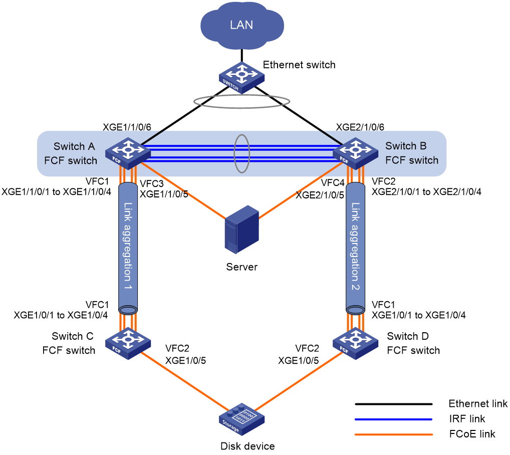
Requirements analysis
To transmit the storage traffic over lossless Ethernet links in the SANs, perform the following tasks:
· Configure DCBX, PFC in auto mode, and ETS on the Ethernet interfaces connecting the switches to the server.
· Enable PFC by force on the Ethernet interfaces connecting switches.
To implement link backup between the server and the disk device, use two separate SANs to provide connections between the server and the disk device. The two SANs can use the same VSAN. The two separate VSANs are as follows:
· One physical SAN is formed by the server, Switch A, Switch C, and the disk device.
· The other physical SAN is formed by the server, Switch B, Switch D, and the disk device.
To transmit the Ethernet traffic of the LAN in VLAN 1001, configure the following interfaces to allow VLAN 1001:
· The Ethernet interfaces connecting Switch A and Switch B to the LAN.
· The Ethernet interfaces connecting Switch A and Switch B to the server.
To transmit the storage traffic of the SANs in VSAN 100, configure the interfaces connecting the four FCF switches to the SANs to allow VSAN 100.
To transmit the storage traffic of VSAN 100 within VLAN 4001, map VLAN 4001 to VSAN 100.
To avoid physical loops in a complex LAN, enable STP on the Ethernet interfaces connecting Switch A and Switch B to the LAN. In this example, you do not need to enable STP, because the LAN is simple and will not have loops.
To prevent loops on the interfaces that connect Switch A and Switch B to the server, configure the interfaces as edge ports and enable BPDU guard. An edge port does not participate in spanning tree calculation and can rapidly transition to the forwarding state. When the server logs in to Switch A or Switch B again, traffic loss is minimized for the server.
To prevent STP from blocking the interfaces that are responsible for forwarding storage traffic on Switch A and Switch B, disable STP on the interfaces connecting the four FCF switches.
For the server to access the resources in the disk device, configure the members in the default zone to access each other.
To increase the bandwidth for the link between Switch A and Switch C and implement link backup and load sharing, configure Ethernet link aggregation group 1.
To increase the bandwidth for the link between Switch B and Switch D and implement link backup and load sharing, configure Ethernet link aggregation group 2.
For the VFC interfaces to correctly perform PFC when both FC interfaces and VFC interfaces are used, configure FC interfaces to trust the 802.1p priorities in incoming packets.
Restrictions and guidelines
As a best practice, build the fabric dynamically and use FSPF for FC routing when the SANs are complex.
By default, interfaces on the device are disabled (in ADM or Administratively Down state). To have an interface operate, you must use the undo shutdown command to enable that interface.
Configuring Switch A
1. Configure the switch to operate in advanced mode, save the configuration, and reboot the switch. (Skip this step if the switch is operating in advanced mode.)
<SwitchA> system-view
[SwitchA] system-working-mode advance
[SwitchA] save
[SwitchA] quit
<SwitchA> reboot
2. Configure VLANs and interfaces:
# Create VLANs 1001 and 4001, which are intended to transmit Ethernet traffic and storage traffic, respectively.
<SwitchA> system-view
[SwitchA] vlan 1001
[SwitchA-vlan1001] description ToLAN
[SwitchA-vlan1001] quit
[SwitchA] vlan 4001
[SwitchA-vlan4001] description ToSAN
[SwitchA-vlan4001] quit
# Enable STP globally.
[SwitchA] stp global enable
# Enable BPDU guard globally.
[SwitchA] stp bpdu-protection
# Configure FortyGigE 1/0/5 as a hybrid port.
[SwitchA] interface fortygige 1/0/5
[SwitchA-FortyGigE1/0/5] port link-type hybrid
# Assign FortyGigE 1/0/5 to VLAN 1001 as an untagged member.
[SwitchA-FortyGigE1/0/5] port hybrid vlan 1001 untagged
# Assign FortyGigE 1/0/5 to VLAN 4001 as a tagged member.
[SwitchA-FortyGigE1/0/5] port hybrid vlan 4001 tagged
# Set the PVID to VLAN 1001 for FortyGigE 1/0/5.
[SwitchA-FortyGigE1/0/5] port hybrid pvid vlan 1001
# Disable STP on FortyGigE 1/0/5.
[SwitchA-FortyGigE1/0/5] undo stp enable
# Configure FortyGigE 1/0/5 as an edge port.
[SwitchA-FortyGigE1/0/5] stp edged-port
# Enable BPDU guard on FortyGigE 1/0/5.
[SwitchA-FortyGigE1/0/5] stp port bpdu-protection enable
[SwitchA-FortyGigE1/0/5] quit
# Configure FortyGigE 1/0/6 as a trunk port, and assign the interface to VLAN 1001.
[SwitchA] interface fortygige 1/0/6
[SwitchA-FortyGigE1/0/6] port link-type trunk
[SwitchA-FortyGigE1/0/6] port trunk permit vlan 1001
# Enable STP on FortyGigE 1/0/6.
[SwitchA-FortyGigE1/0/6] stp enable
[SwitchA-FortyGigE1/0/6] quit
# Create Layer 2 aggregate interface 1, and configure it to operate in dynamic aggregation mode.
[SwitchA] interface bridge-aggregation 1
[SwitchA-Bridge-Aggregation1] link-aggregation mode dynamic
# Disable STP on Layer 2 aggregate interface 1.
[SwitchA-Bridge-Aggregation1] undo stp enable
[SwitchA-Bridge-Aggregation1] quit
# Assign FortyGigE 1/0/1 through FortyGigE 1/0/4 to Layer 2 aggregation group 1.
[SwitchA] interface fortygige 1/0/1
[SwitchA-FortyGigE1/0/1] port link-aggregation group 1
[SwitchA-FortyGigE1/0/1] quit
[SwitchA] interface fortygige 1/0/2
[SwitchA-FortyGigE1/0/2] port link-aggregation group 1
[SwitchA-FortyGigE1/0/2] quit
[SwitchA] interface fortygige 1/0/3
[SwitchA-FortyGigE1/0/3] port link-aggregation group 1
[SwitchA-FortyGigE1/0/3] quit
[SwitchA] interface fortygige 1/0/4
[SwitchA-FortyGigE1/0/4] port link-aggregation group 1
[SwitchA-FortyGigE1/0/4] quit
# Configure Layer 2 aggregate interface 1 as a trunk port, and assign the aggregate interface to VLAN 4001.
[SwitchA] interface bridge-aggregation 1
[SwitchA-Bridge-Aggregation1] port link-type trunk
[SwitchA-Bridge-Aggregation1] port trunk permit vlan 4001
[SwitchA-Bridge-Aggregation1] quit
3. Configure DCBX:
# Enable LLDP globally.
[SwitchA] lldp global enable
# Create a Layer 2 ACL named DCBX.
[SwitchA] acl mac name DCBX
# Configure the ACL to permit FCoE packets (whose protocol number is 0x8906) to pass through.
[SwitchA-acl-mac-DCBX] rule 0 permit type 8906 ffff
# Configure the ACL to permit FIP protocol packets (whose protocol number is 0x8914) to pass through.
[SwitchA-acl-mac-DCBX] rule 5 permit type 8914 ffff
[SwitchA-acl-mac-DCBX] quit
# Create a class named DCBX, with the operator of the class as OR.
[SwitchA] traffic classifier DCBX operator or
# Use ACL DCBX as the match criterion of the class.
[SwitchA-classifier-DCBX] if-match acl mac name DCBX
[SwitchA-classifier-DCBX] quit
# Create a behavior named DCBX, and configure the behavior to mark packets with 802.1p priority value 3.
[SwitchA] traffic behavior DCBX
[SwitchA-behavior-DCBX] remark dot1p 3
[SwitchA-behavior-DCBX] quit
# Create a QoS policy named DCBX.
[SwitchA] qos policy DCBX
# Associate class DCBX with traffic behavior DCBX in the QoS policy, and specify that the association apply to DCBX.
[SwitchA-qospolicy-DCBX] classifier DCBX behavior DCBX mode dcbx
[SwitchA-qospolicy-DCBX] quit
# Enable LLDP and DCBX TLV advertising on FortyGigE 1/0/5.
[SwitchA] interface fortygige 1/0/5
[SwitchA-FortyGigE1/0/5] lldp enable
[SwitchA-FortyGigE1/0/5] lldp tlv-enable dot1-tlv dcbx
# Apply QoS policy DCBX to the outgoing traffic of FortyGigE 1/0/5.
[SwitchA-FortyGigE1/0/5] qos apply policy DCBX outbound
4. Configure PFC:
# Enable PFC in auto mode on FortyGigE 1/0/5.
[SwitchA-FortyGigE1/0/5] priority-flow-control auto
# Enable PFC for 802.1p priority 3 on FortyGigE 1/0/5.
[SwitchA-FortyGigE1/0/5] priority-flow-control no-drop dot1p 3
# Configure FortyGigE 1/0/5 to trust the 802.1p priority carried in incoming packets.
[SwitchA-FortyGigE1/0/5] qos trust dot1p
[SwitchA-FortyGigE1/0/5] quit
# Enable PFC by force on FortyGigE 1/0/1.
[SwitchA] interface fortygige 1/0/1
[SwitchA-FortyGigE1/0/1] priority-flow-control enable
# Enable PFC for 802.1p priority 3 on FortyGigE 1/0/1.
[SwitchA-FortyGigE1/0/1] priority-flow-control no-drop dot1p 3
# Configure FortyGigE 1/0/1 to trust the 802.1p priority carried in incoming packets.
[SwitchA-FortyGigE1/0/1] qos trust dot1p
[SwitchA-FortyGigE1/0/1] quit
# Configure FortyGigE 1/0/2 through FortyGigE 1/0/4 in the same way FortyGigE 1/0/1 is configured.
[SwitchA] interface fortygige 1/0/2
[SwitchA-FortyGigE1/0/2] priority-flow-control enable
[SwitchA-FortyGigE1/0/2] priority-flow-control no-drop dot1p 3
[SwitchA-FortyGigE1/0/2] qos trust dot1p
[SwitchA-FortyGigE1/0/2] quit
[SwitchA] interface fortygige 1/0/3
[SwitchA-FortyGigE1/0/3] priority-flow-control enable
[SwitchA-FortyGigE1/0/3] priority-flow-control no-drop dot1p 3
[SwitchA-FortyGigE1/0/3] qos trust dot1p
[SwitchA-FortyGigE1/0/3] quit
[SwitchA] interface fortygige 1/0/4
[SwitchA-FortyGigE1/0/4] priority-flow-control enable
[SwitchA-FortyGigE1/0/4] priority-flow-control no-drop dot1p 3
[SwitchA-FortyGigE1/0/4] qos trust dot1p
[SwitchA-FortyGigE1/0/4] quit
5. Configure ETS:
# Configure the 802.1p-local priority mapping table as follows:
¡ Map 802.1p priority value 3 to local precedence 1.
¡ Map the other 802.1p priority values to local precedence 0.
[SwitchA] qos map-table dot1p-lp
[SwitchA-maptbl-dot1p-lp] import 3 export 1
[SwitchA-maptbl-dot1p-lp] import 0 export 0
[SwitchA-maptbl-dot1p-lp] import 1 export 0
[SwitchA-maptbl-dot1p-lp] import 2 export 0
[SwitchA-maptbl-dot1p-lp] import 4 export 0
[SwitchA-maptbl-dot1p-lp] import 5 export 0
[SwitchA-maptbl-dot1p-lp] import 6 export 0
[SwitchA-maptbl-dot1p-lp] import 7 export 0
[SwitchA-maptbl-dot1p-lp] quit
# Configure WRR on FortyGigE 1/0/5 as follows:
¡ Assign 50% of the interface bandwidth to the FCoE traffic (traffic assigned to queue 1).
¡ Assign 50% of the interface bandwidth to the LAN traffic (traffic assigned to queue 0).
[SwitchA] interface fortygige 1/0/5
[SwitchA-FortyGigE1/0/5] qos wrr af1 group 1 byte-count 1
[SwitchA-FortyGigE1/0/5] qos wrr be group 1 byte-count 1
# Assign the other queues to the SP group on FortyGigE 1/0/5.
[SwitchA-FortyGigE1/0/5] qos wrr af2 group sp
[SwitchA-FortyGigE1/0/5] qos wrr af3 group sp
[SwitchA-FortyGigE1/0/5] qos wrr af4 group sp
[SwitchA-FortyGigE1/0/5] qos wrr ef group sp
[SwitchA-FortyGigE1/0/5] qos wrr cs6 group sp
[SwitchA-FortyGigE1/0/5] qos wrr cs7 group sp
[SwitchA-FortyGigE1/0/5] quit
6. Configure FCoE:
# Configure the switch to operate in FCF mode.
[SwitchA] fcoe-mode fcf
# Enable the fabric configuration feature for VSAN 100. By default, the fabric configuration feature is enabled.
[SwitchA] vsan 100
[SwitchA-vsan100] domain configure enable
# Set the domain ID to 2.
[SwitchA-vsan100] domain-id 2 preferred
Nondisruptive reconfiguration might be performed or the switch might be isolated. Continue? [Y/N]:y
# Enable FSPF.
[SwitchA-vsan100] fspf enable
[SwitchA-vsan100] quit
# Create VFC 1.
[SwitchA] interface vfc 1
# Configure the mode of VFC 1 as E.
[SwitchA-Vfc1] fc mode e
# Bind VFC 1 to Layer 2 aggregate interface 1.
[SwitchA-Vfc1] bind interface bridge-aggregation 1
# Assign VFC 1 to VSAN 100 as a trunk port.
[SwitchA-Vfc1] port trunk vsan 100
# Create VFC 2.
[SwitchA] interface vfc 2
# Configure the mode of VFC 2 as F.
[SwitchA-Vfc2] fc mode f
# Bind VFC 2 to FortyGigE1/0/5.
[SwitchA-Vfc2] bind interface fortygige 1/0/5
# Assign VFC 2 to VSAN 100 as a trunk port.
[SwitchA-Vfc2] port trunk vsan 100
[SwitchA-Vfc2] quit
# Enable FC and FCoE in VLAN 4001 and map VLAN 4001 to VSAN 100.
[SwitchA] vlan 4001
[SwitchA-vlan4001] fcoe enable vsan 100
[SwitchA-vlan4001] quit
# In VSAN 100, configure the members in the default zone to access each other.
[SwitchA] vsan 100
[SwitchA-vsan100] zone default-zone permit
[SwitchA-vsan100] quit
Configuring Switch B
Configure Switch B in the same way Switch A is configured. On Switch B, the Layer 2 aggregate interface is Bridge-Aggregation2.
Configuring Switch C
1. Configure the switch to operate in advanced mode, save the configuration, and reboot the switch. (Skip this step if the switch is operating in advanced mode.)
<SwitchC> system-view
[SwitchC] system-working-mode advance
[SwitchC] save
[SwitchC] quit
<SwitchC> reboot
2. Configure VLANs and interfaces:
# Create VLAN 4001, which is intended to transmit storage traffic.
<SwitchC> system-view
[SwitchC] vlan 4001
[SwitchC-vlan4001] description ToSAN
[SwitchC-vlan4001] quit
# Create Layer 2 aggregate interface 1, configure it to operate in dynamic aggregation mode, and disable STP.
[SwitchC] interface bridge-aggregation 1
[SwitchC-Bridge-Aggregation1] link-aggregation mode dynamic
[SwitchC-Bridge-Aggregation1] undo stp enable
[SwitchC-Bridge-Aggregation1] quit
# Assign FortyGigE 1/0/1 through FortyGigE 1/0/4 to Layer 2 aggregation group 1.
[SwitchC] interface fortygige 1/0/1
[SwitchC-FortyGigE1/0/1] port link-aggregation group 1
[SwitchC-FortyGigE1/0/1] quit
[SwitchC] interface fortygige 1/0/2
[SwitchC-FortyGigE1/0/2] port link-aggregation group 1
[SwitchC-FortyGigE1/0/2] quit
[SwitchC] interface fortygige 1/0/3
[SwitchC-FortyGigE1/0/3] port link-aggregation group 1
[SwitchC-FortyGigE1/0/3] quit
[SwitchC] interface fortygige 1/0/4
[SwitchC-FortyGigE1/0/4] port link-aggregation group 1
[SwitchC-FortyGigE1/0/4] quit
# Configure Layer 2 aggregate interface 1 as a trunk port, and assign the aggregate interface to VLAN 4001.
[SwitchC] interface bridge-aggregation 1
[SwitchC-Bridge-Aggregation1] port link-type trunk
[SwitchC-Bridge-Aggregation1] port trunk permit vlan 4001
[SwitchC-Bridge-Aggregation1] quit
3. Configure PFC:
# Enable PFC by force on FortyGigE 1/0/1.
[SwitchC] interface fortygige 1/0/1
[SwitchC-FortyGigE1/0/1] priority-flow-control enable
# Enable PFC for 802.1p priority 3 on FortyGigE 1/0/1.
[SwitchC-FortyGigE1/0/1] priority-flow-control no-drop dot1p 3
# Configure FortyGigE 1/0/1 to trust the 802.1p priority carried in incoming packets.
[SwitchC-FortyGigE1/0/1] qos trust dot1p
[SwitchC-FortyGigE1/0/1] quit
# Configure FortyGigE 1/0/2 through FortyGigE 1/0/4 in the same way FortyGigE 1/0/1 is configured.
[SwitchC] interface fortygige 1/0/2
[SwitchC-FortyGigE1/0/2] priority-flow-control enable
[SwitchC-FortyGigE1/0/2] priority-flow-control no-drop dot1p 3
[SwitchC-FortyGigE1/0/2] qos trust dot1p
[SwitchC-FortyGigE1/0/2] quit
[SwitchC] interface fortygige 1/0/3
[SwitchC-FortyGigE1/0/3] priority-flow-control enable
[SwitchC-FortyGigE1/0/3] priority-flow-control no-drop dot1p 3
[SwitchC-FortyGigE1/0/3] qos trust dot1p
[SwitchC-FortyGigE1/0/3] quit
[SwitchC] interface fortygige 1/0/4
[SwitchC-FortyGigE1/0/4] priority-flow-control enable
[SwitchC-FortyGigE1/0/4] priority-flow-control no-drop dot1p 3
[SwitchC-FortyGigE1/0/4] qos trust dot1p
[SwitchC-FortyGigE1/0/4] quit
4. Configure FC and FCoE:
# Configure the switch to operate in FCF mode.
[SwitchC] fcoe-mode fcf
# Enable the fabric configuration feature for VSAN 100. By default, the fabric configuration feature is enabled.
[SwitchC] vsan 100
[SwitchC-vsan100] domain configure enable
# Set the switch priority to 1, so the switch can be selected as the principal switch.
[SwitchC-vsan100] priority 1
# Set the domain ID to 1.
[SwitchC-vsan100] domain-id 1 preferred
Nondisruptive reconfiguration might be performed or the switch might be isolated. Continue? [Y/N]:y
# Enable FSPF.
[SwitchC-vsan100] fspf enable
[SwitchC-vsan100] quit
# Change FortyGigE 1/0/5 into FC 1/0/5.
[SwitchC] interface fortygige 1/0/5
[SwitchC-FortyGigE1/0/5] port-type fc
# Configure the mode of FC 1/0/5 as F.
[SwitchC-Fc1/0/5] fc mode f
# Configure FC 1/0/5 to autonegotiate the speed.
[SwitchC-Fc1/0/5] speed auto
# Configure FC 1/0/5 to trust the 802.1p priorities carried in incoming packets.
[SwitchC-Fc1/0/5] qos trust dot1p
# Assign FC 1/0/5 to VSAN 100 as an access port.
[SwitchC-Fc1/0/5] port access vsan 100
[SwitchC-Fc1/0/5] quit
# Create VFC 1.
[SwitchC] interface vfc 1
# Configure the mode of VFC 1 as E.
[SwitchC-Vfc1] fc mode e
# Bind VFC 1 to Layer 2 aggregate interface 1.
[SwitchC-Vfc1] bind interface bridge-aggregation 1
# Assign VFC 1 to VSAN 100 as a trunk port.
[SwitchC-Vfc1] port trunk vsan 100
[SwitchC-Vfc1] quit
# Enable FC and FCoE in VLAN 4001 and map VLAN 4001 to VSAN 100.
[SwitchC] vlan 4001
[SwitchC-vlan4001] fcoe enable vsan 100
[SwitchC-vlan4001] quit
# In VSAN 100, configure the members in the default zone to access each other.
[SwitchC] vsan 100
[SwitchC-vsan100] zone default-zone permit
[SwitchC-vsan100] quit
Configuring Switch D
Configure Switch D in the same way Switch C is configured. On Switch D, the Layer 2 aggregate interface is Bridge-Aggregation2.
Verifying the configuration on Switch A
This example uses Switch A.
# Display the domain information of VSAN 100.
[SwitchA] display fc domain vsan 100
Domain Information of VSAN 100:
Running time information:
State: Stable
Switch WWN: 48:33:43:2d:46:43:1A:1A
Fabric name: 48:33:43:2d:46:43:1C:1C
Priority: 128
Domain ID: 2
Configuration information:
Domain configure: Enabled
Domain auto-reconfigure: Disabled
Fabric name: 48:33:43:2d:46:43:1A:1A
Priority: 128
Domain ID: 2 (preferred)
Principal switch running time information:
Priority: 1
Path Interface
Upstream Vfc1
The output shows that the domain configuration is complete on Switch A, and the principal switch assigns domain ID 2 to Switch A.
# Display the domain ID list of VSAN 100.
[SwitchA] display fc domain-list vsan 100
Domain list of VSAN 100:
Number of domains: 2
Domain ID WWN
0x01(1) 48:33:43:2d:46:43:1C:1C [Principal]
0x02(2) 48:33:43:2d:46:43:1A:1A [Local]
The output shows that Switch C is elected as the principal switch, and the principal switch assigns the configured domain ID (ID 1) to itself.
# Display the routing table information in VSAN 100.
[SwitchA] display fc routing-table vsan 100
Routing Table: VSAN 100
Destinations : 5 Routes : 5
Destination/mask Protocol Preference Cost Interface
0x010000/8 FSPF 20 100 Vfc1
0xfffc01/24 DIRECT 0 0 InLoop0
0xfffffa/24 DIRECT 0 0 InLoop0
0xfffffc/24 DIRECT 0 0 InLoop0
0xfffffd/24 DIRECT 0 0 InLoop0
The output shows that an FSPF route from Switch A to Switch C exists, with the outgoing interface as VFC 1.
# Display the node login information for VSAN 100.
[SwitchA] display fc login vsan 100
Interface VSAN FCID Node WWN Port WWN
Vfc2 100 0x020000 21:01:00:1b:32:a0:fa:12 21:01:00:1b:32:a0:fa:11
# Display the brief information about the name server database in VSAN 100.
[SwitchA] display fc name-service database vsan 100
VSAN 100:
FCID Type PWWN(vendor) FC4-type:feature
0x010000 0x01(N) 10:00:00:05:30:00:25:a3 SCSI-FCP:Target
0x020000 0x01(N) 21:01:00:1b:32:a0:fa:11 SCSI-FCP:Initiator
Verifying the configuration on Switch B
Verify the configuration on Switch B in the same way as on Switch A.
Verifying the configuration on Switch C
This example uses Switch C.
# Display the node login information for VSAN 100.
[SwitchC] display fc login vsan 100
Interface VSAN FCID Node WWN Port WWN
Fc1/0/5 100 0x010000 10:00:00:05:30:00:25:a4 10:00:00:05:30:00:25:a3
Verifying the configuration on Switch D
Verify the configuration on Switch D in the same way as on Switch C.
Appendixes
Appendix A Fabric address assignment
Table 11 Fabric address assignment
|
FC address |
Description |
|
0x000000 |
Undefined (when an N_Port uses FLOGI to request for an address, an all-zero FC address is used). |
|
0x000001–0x00ffff |
Reserved. |
|
0x010000–0xefffff |
N_Port address. |
|
0xf00000–0xfff9ff |
Reserved. |
|
0xfffa00–0xfffa0f |
Reserved for internal loopback. |
|
0xfffa10–0xfffa1f |
Reserved for external loopback. |
|
0xfffa20–0xfffaff |
Reserved. |
|
0xfffb00–0xfffbff |
Reserved for multicast. |
|
0xfffc00 |
Reserved. |
|
0xfffc01–0xfffcef |
Domain controller addresses. |
|
0xfffcf0–0xfffef |
Reserved. |
|
0xfffff0–0xfffffc |
Well-known addresses. |
|
0xfffffd |
Fabric controller address, representing all E_Ports. |
|
0xfffffe |
F_Port controller address, representing all F_Ports. |
|
0xffffff |
Broadcast address. |
Appendix B Well-known fabric addresses
Table 12 Purposes of well-known fabric addresses
|
FC address |
Description |
|
0xfffff0 |
N_Port controller, representing all N_Ports. |
|
0xfffff1–0xfffff3 |
Reserved. |
|
0xfffff4 |
Event services. |
|
0xfffff5 |
Multicast server. |
|
0xfffff6 |
Clock synchronization services. |
|
0xfffff7 |
Security key distribution services. |
|
0xfffff8 |
Alias services. |
|
0xfffff9 |
Reserved. |
|
0xfffffa |
Management services. |
|
0xfffffb |
Time services. |
|
0xfffffc |
Path services (name services). |
