- Table of Contents
-
- 05-Layer 3 - IP Routing Configuration Examples
- 01-H3C_BGP_Configuration_Examples
- 02-H3C_BGP_Route_Selection_Configuration_Examples
- 03-H3C_IPv6_IS-IS_Configuration_Examples
- 04-H3C_IS-IS_Route_Summarization_Configuration_Examples
- 05-H3C_IS-IS_Configuration_Examples
- 06-H3C_OSPFv3_Configuration_Examples
- 07-H3C_OSPF_Configuration_Examples
- 08-H3C_Policy-Based_Routing_Configuration_Examples
- 09-H3C_Routing_Policy_Configuration_Examples
- 10-H3C_IPv6_over_IPv4_Manual_Tunneling_with_OSPFv3_Configuration_Examples
- 11-H3C_GRE_with_OSPF_Configuration_Examples
- Related Documents
-
| Title | Size | Download |
|---|---|---|
| 08-H3C_Policy-Based_Routing_Configuration_Examples | 91.14 KB |
H3C Policy-Based Routing Configuration Examples
Software version: Release 7585P05
Document version: 6W100-20200330
Copyright © 2020 New H3C Technologies Co., Ltd. All rights reserved.
No part of this manual may be reproduced or transmitted in any form or by any means without prior written consent of New H3C Technologies Co., Ltd.
Except for the trademarks of New H3C Technologies Co., Ltd., any trademarks that may be mentioned in this document are the property of their respective owners.
The information in this document is subject to change without notice.
Contents
Introduction
This document provides PBR configuration examples.
PBR uses a user-defined policy to route packets based on fields such as the source address, destination address, and IP precedence. PBR takes precedence over destination-based routing.
Prerequisites
The configuration examples in this document were created and verified in a lab environment, and all the devices were started with the factory default configuration. When you are working on a live network, make sure you understand the potential impact of every command on your network.
This document assumes that you have basic knowledge of H3C PBR.
Restrictions and guidelines
When you configure PBR, follow these restrictions and guidelines:
· The device supports only interface PBR, which guides the forwarding of packets received on an interface. Interface PBR does not take effect on locally generated packets.
· When you configure the action of forwarding traffic to a next hop, do not specify the following addresses:
¡ An IPv6 address in an IPv4 ACL rule.
¡ An IPv4 address in an IPv6 ACL rule.
Example: Configuring PBR
Network configuration
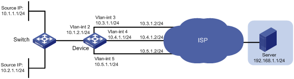
As shown in Figure 1, on Device, all packets destined for Server are forwarded based on the routing table to the next hop 10.4.1.2 by default.
Configure PBR to meet the following requirements:
· Packets with source IPv4 address 10.2.1.1 received on VLAN-interface 2 are forwarded to the next hop 10.5.1.2.
· HTTP packets with source IPv4 addresses other than 10.2.1.1 received on VLAN-interface 2 are forwarded to the next hop 10.3.1.2.
Analysis
To forward the two types of packets to different next hops, you must perform the following tasks:
· Configure two ACLs to classify the two types of packets.
· Configure two policy nodes to forward the packets to the specified next hops.
To ensure that HTTP packets with source address 10.2.1.1 are forwarded to the next hop 10.5.1.2, specify a node with a smaller number to match the HTTP packets.
Procedures
# Configure an IPv4 address for VLAN-interface 2.
<Device> system-view
[Device] interface vlan-interface 2
[Device-Vlan-interface2] ip address 10.1.2.1 255.255.255.0
[Device-Vlan-interface2] quit
# Configure IPv4 addresses for other interfaces, as shown in Figure 1. (Details not shown.)
# Configure three static routes and configure 10.4.1.2 as the default next hop.
[Device] ip route-static 192.168.1.0 24 10.3.1.2
[Device] ip route-static 192.168.1.0 24 10.4.1.2 preference 40
[Device] ip route-static 192.168.1.0 24 10.5.1.2
# Create ACL 3005 to match packets with source address 10.2.1.1.
[Device] acl advanced 3005
[Device-acl-ipv4-adv-3005] rule 0 permit ip source 10.2.1.1 0
[Device-acl-ipv4-adv-3005] quit
# Create ACL 3006 to match HTTP packets.
[Device] acl advanced 3006
[Device-acl-ipv4-adv-3006] rule 0 permit tcp destination-port eq www
[Device-acl-ipv4-adv-3006] quit
# Configure Node 0 for policy pbr1 to forward packets matching ACL 3005 to the next hop 10.5.1.2.
[Device] policy-based-route pbr1 permit node 0
[Device-pbr-pbr1-0] if-match acl 3005
[Device-pbr-pbr1-0] apply next-hop 10.5.1.2
[Device-pbr-pbr1-0] quit
# Configure Node 1 for policy pbr1 to forward packets matching ACL 3006 to the next hop 10.3.1.2.
[Device] policy-based-route pbr1 permit node 1
[Device-pbr-pbr1-1] if-match acl 3006
[Device-pbr-pbr1-1] apply next-hop 10.3.1.2
[Device-pbr-pbr1-1] quit
# Apply policy pbr1 to VLAN-interface 2.
[Device] interface vlan-interface 2
[Device-Vlan-interface2] ip policy-based-route pbr1
[Device-Vlan-interface2] quit
Verifying the configuration
# On Device, display PBR policy information.
[Device] display ip policy-based-route policy pbr1
Policy name: pbr1
node 0 permit:
if-match acl 3005
apply next-hop 10.5.1.2
node 1 permit:
if-match acl 3006
apply next-hop 10.3.1.2
The output shows that the PBR configurations are successful.
# On Switch, display the path for forwarding non-HTTP packets with source address 10.1.1.1.
|
|
NOTE: Before you use a tracert command, perform the following tasks: · Enable sending of ICMP timeout packets on the intermediate devices. · Enable sending of ICMP destination unreachable packets on the destination device. |
<Switch> tracert -a 10.1.1.1 192.168.1.1
traceroute to 192.168.1.1 (192.168.1.1) from 10.1.1.1, 30 hops at most, 40 bytes
each packet, press CTRL_C to break
1 10.1.2.1 (10.1.2.1) 2.178 ms 1.364 ms 1.058 ms
2 10.4.1.2 (10.4.1.2) 1.548 ms 1.248 ms 1.112 ms
3 192.168.1.1 (192.168.1.1) 1.594 ms 1.321 ms 1.093 ms
The output shows that non-HTTP packets with source address 10.1.1.1 are forwarded to the next hop 10.4.1.2.
# On Switch, display the path for forwarding packets with source address 10.2.1.1.
<Switch> tracert -a 10.2.1.1 192.168.1.1
traceroute to 192.168.1.1 (192.168.1.1) from 10.2.1.1, 30 hops at most, 40 bytes
each packet, press CTRL_C to break
1 10.1.2.1 (10.1.2.1) 1.721 ms 1.226 ms 1.050 ms
2 10.5.1.2 (10.5.1.2) 4.494 ms 1.385 ms 1.170 ms
3 192.168.1.1 (192.168.1.1) 1.448 ms 1.304 ms 1.093 ms
The output shows that packets with source address 10.2.1.1 are forwarded to the next hop 10.5.1.2.
Configuration files
#
vlan 1
#
vlan 2 to 5
#
policy-based-route pbr1 permit node 0
if-match acl 3005
apply next-hop 10.5.1.2
#
policy-based-route pbr1 permit node 1
if-match acl 3006
apply next-hop 10.3.1.2
#
interface Vlan-interface2
ip address 10.1.2.1 255.255.255.0
ip policy-based-route pbr1
#
interface Vlan-interface3
ip address 10.3.1.1 255.255.255.0
#
interface Vlan-interface4
ip address 10.4.1.1 255.255.255.0
#
interface Vlan-interface5
ip address 10.5.1.1 255.255.255.0
#
interface Ten-GigabitEthernet3/0/1
port link-mode bridge
port access vlan 2
#
interface Ten-GigabitEthernet3/0/3
port link-mode bridge
port access vlan 3
#
interface Ten-GigabitEthernet3/0/4
port link-mode bridge
port access vlan 4
#
interface Ten-GigabitEthernet3/0/5
port link-mode bridge
port access vlan 5
#
ip route-static 192.168.1.0 24 10.3.1.2
ip route-static 192.168.1.0 24 10.4.1.2 preference 40
ip route-static 192.168.1.0 24 10.5.1.2
#
acl advanced 3005
rule 0 permit ip source 10.2.1.1 0
#
acl advanced 3006
rule 0 permit tcp destination-port eq www
#
Example: Configuring IPv6 PBR
Network configuration
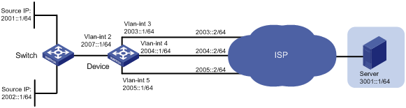
As shown in Figure 2, on Device, all packets destined for Server are forwarded based on the routing table to the next hop 2004::2 by default.
Configure IPv6 PBR to meet the following requirements:
· Packets with source IPv6 address 2002::1 received on VLAN-interface 2 are forwarded to the next hop 2005::2.
· HTTP packets with source IPv6 addresses other than 2002::1 received on VLAN-interface 2 are forwarded to the next hop 2003::2.
Analysis
To forward the two types of packets to different next hops, you must perform the following tasks:
· Configure two ACLs to classify the two types of packets.
· Configure two policy nodes to forward the packets to the specified next hops.
To ensure that HTTP packets with source address 2002::1 are forwarded to the next hop 2005::2, specify a node with a smaller number to match the HTTP packets.
Procedures
# Configure an IPv6 address for VLAN-interface 2.
<Device> system-view
[Device] interface vlan-interface 2
[Device-Vlan-interface2] ipv6 address 2007::1 64
[Device-Vlan-interface2] quit
# Configure IPv6 addresses for other interfaces, as shown in Figure 2. (Details not shown.)
# Configure three static routes and configure 2004::2/64 as the default next hop.
[Device] ipv6 route-static 3001::1 64 2003::2
[Device] ipv6 route-static 3001::1 64 2004::2 preference 40
[Device] ipv6 route-static 3001::1 64 2005::2
# Create IPv6 ACL 3005 to match packets with source address 2002::1.
[Device] acl ipv6 advanced 3005
[Device-acl-ipv6-adv-3005] rule 0 permit ipv6 source 2002::1/128
[Device-acl-ipv6-adv-3005] quit
# Create IPv6 ACL 3006 to match HTTP packets.
[Device] acl ipv6 advanced 3006
[Device-acl-ipv6-adv-3006] rule 0 permit tcp destination-port eq www
[Device-acl-ipv6-adv-3006] quit
# Configure Node 0 for policy pbr1 to forward packets matching IPv6 ACL 3005 to the next hop 2005::2.
[Device] ipv6 policy-based-route pbr1 permit node 0
[Device-pbr6-pbr1-0] if-match acl 3005
[Device-pbr6-pbr1-0] apply next-hop 2005::2
[Device-pbr6-pbr1-0] quit
# Configure Node 1 for policy pbr1 to forward packets matching IPv6 ACL 3006 to the next hop 2003::2.
[Device] ipv6 policy-based-route pbr1 permit node 1
[Device-pbr6-pbr1-1] if-match acl 3006
[Device-pbr6-pbr1-1] apply next-hop 2003::2
[Device-pbr6-pbr1-1] quit
# Apply policy pbr1 to VLAN-interface 2.
[Device] interface vlan-interface 2
[Device-Vlan-interface2] ipv6 policy-based-route pbr1
[Device-Vlan-interface2] quit
Verifying the configuration
# On Device, display IPv6 PBR policy information.
[Device] display ipv6 policy-based-route policy pbr1
Policy name: pbr1
node 0 permit:
if-match acl 3005
apply next-hop 2005::2
node 1 permit:
if-match acl 3006
apply next-hop 2003::2
The output shows that the IPv6 PBR configurations are successful.
# On Device, verify the forwarding of packets with source address 2002::1. (Details not shown.)
· If 2005::2 is reachable, packets are forwarded to the next hop 2005::2.
· If 2005::2 is not reachable, packets are forwarded to the next hop 2004::2 according to the routing table.
# On Device, verify the forwarding of HTTP packets. (Details not shown.)
· If 2003::2 is reachable, packets are forwarded to the next hop 2003::2.
· If 2003::2 is not reachable, packets are forwarded to the next hop 2004::2 according to the routing table.
Configuration files
#
vlan 1
#
vlan 2 to 5
#
ipv6 policy-based-route pbr1 permit node 0
if-match acl 3005
apply next-hop 2005::2
#
ipv6 policy-based-route pbr1 permit node 1
if-match acl 3006
apply next-hop 2003::2
#
interface Vlan-interface2
ipv6 policy-based-route pbr1
ipv6 address 2007::1/64
#
interface Vlan-interface3
ipv6 address 2003::1 64
#
interface Vlan-interface4
ipv6 address 2004::1 64
#
interface Vlan-interface5
ipv6 address 2005::1 64
#
interface Ten-GigabitEthernet5/0/1
port link-mode bridge
port access vlan 2
#
interface Ten-GigabitEthernet5/0/3
port link-mode bridge
port access vlan 3
#
interface Ten-GigabitEthernet5/0/4
port link-mode bridge
port access vlan 4
#
interface Ten-GigabitEthernet5/0/5
port link-mode bridge
port access vlan 5
#
ipv6 route-static 3001:: 64 2003::2
ipv6 route-static 3001:: 64 2004::2 preference 40
ipv6 route-static 3001:: 64 2005::2
#
acl ipv6 advanced 3005
rule 0 permit ipv6 source 2002::1/128
#
acl ipv6 advanced 3006
rule 0 permit tcp destination-port eq www
#
Related documentation
· H3C S7500E Switch Series Layer 3—IP Routing Command Reference-R758X
· H3C S7500E Switch Series Layer 3—IP Routing Configuration Guide-R758X
