- Table of Contents
- Related Documents
-
| Title | Size | Download |
|---|---|---|
| 01-Text | 2.39 MB |
Contents
PPP link establishment process
Feature and hardware compatibility
Command and hardware compatibility
Enabling PPP encapsulation on an interface
Configuring PPP authentication
Configuring the polling feature
Enabling IP header compression
Enabling PPP link quality monitoring
Configuring the nas-port-type attribute
Configuring MP by using a VT interface
Configuring MP through an MP-group interface
Configuring short sequence number header format negotiation
Configuring the MP endpoint descriptor
Displaying and maintaining PPP and MP
PPP and MP configuration examples
One-way PAP authentication configuration example
Two-way PAP authentication configuration example
One-way CHAP authentication configuration example
IP address negotiation configuration examples
MP binding mode configuration examples
Feature and hardware compatibility
Command and hardware compatibility
Setting the maximum number of PPPoE sessions
Limiting the PPPoE access rate
Configuring the NAS-Port-ID attribute
Configuring a dialer interface
Displaying and maintaining PPPoE
Displaying and maintaining PPPoE server
Displaying and maintaining PPPoE client
PPPoE server configuration example
PPPoE server IP address assignment through the local DHCP server configuration example
PPPoE server IP address assignment through a remote DHCP server configuration example
PPPoE server RADIUS-based IP address assignment configuration example
PPPoE client in permanent mode configuration example
PPPoE client in on-demand mode configuration example
PPPoE client in diagnostic mode configuration example
Configuration example for connecting a LAN to the Internet through an ADSL modem
L2TP message types and encapsulation structure
L2TP tunneling modes and tunnel establishment process
Feature and hardware compatibility
Configuring basic L2TP capabilities
Configuring an LAC to initiate tunneling requests for a user
Configuring the source IP address of L2TP tunnel packets
Enabling transferring AVP data in hidden mode
Configuring AAA authentication on an LAC
Configuring an LAC to automatically establish an L2TP tunnel
Configuring an LNS to accept L2TP tunneling requests from an LAC
Configuring user authentication on an LNS
Configuring AAA authentication on an LNS
Configuring optional L2TP parameters
Configuring L2TP tunnel authentication
Setting the DSCP value of L2TP packets
Assigning a tunnel peer to a VPN
Setting the sending window size for an L2TP tunnel
Configuring IMSI/SN binding authentication
Configuring IMSI/SN binding authentication on the LNS
Configuring IMSI/SN binding authentication on the LAC
Configuring IMSI/SN binding authentication on the client
Displaying and maintaining L2TP
Configuration example for NAS-initiated L2TP tunnel
Configuration example for client-initiated L2TP tunnel
Configuration example for LAC-auto-initiated L2TP tunnel
Feature and hardware compatibility
Command and hardware compatibility
Enabling HDLC encapsulation on an interface
Configuring link status polling
Displaying and maintaining HDLC
Configuring HDLC link bundling
Feature and hardware compatibility
Command and hardware compatibility
Configuring an HDLC link bundle interface
Configuration restrictions and guidelines
Assigning an interface to an HDLC link bundle
Configuration restrictions and guidelines
Displaying and maintaining HDLC link bundling
HDLC link bundling configuration example
ISDN PRI configuration prerequisites
Setting the ISDN switch type on an ISDN interface
Setting the ISDN functionality of an ISDN interface
Configuring SPID parameters for the NI switch type
Configuring the TSPID timer and INFORMATION retransmission
Enabling NIT mode for NI-type switches incapable of SPID negotiation
Configuring Q.931 negotiation parameters
Configuring Q.931 call control parameters
Configuring B-channel selection
Configuring calling number verification for incoming calls
Configuring called-number verification for incoming calls
Configuring ISDN calling number identification
Configuring the Q.921 operating parameters
Configuring the data link type of a BRI interface
Configuring per-channel TEI assignment on a BRI interface
Configuring the leased line service for an ISDN BRI interface
Enabling permanent Q.921 link connectivity on an ISDN BRI interface
Enabling persistent Layer 1 activation on a BRI interface
Configuring a BRI interface to supply line power
Configuring the sliding window size on an ISDN BRI interface
Configuring the sliding window size on an ISDN PRI interface
Displaying and maintaining ISDN settings
ISDN PRI configuration example
NI-enabled ISDN BRI configuration example
ATM connections and ATM switching
Feature and hardware compatibility
Configuring the ATM AAL5 encapsulation type
Configuring the ATM service type
Configuring applications carried by ATM
Re-marking the CLP flag value of ATM cells
Displaying and maintaining ATM
ATM PVC transmission priority configuration example
Link state error in IPoA application
Link report error in PPPoA application
PVC state is down when ATM interface state is up
Ping failure after PPPoA configuration
Feature and hardware compatibility
Modem management configuration task list
Configuring modem services on a user line
Setting the answer timeout timer
Enabling a modem to obtain caller numbers
Issuing an AT command to a modem
Setting the country code of a modem
Modem management configuration example
Feature and hardware compatibility
Configuration restrictions and guidelines
3G modem management configuration task list
4G modem management configuration task list
Configuring a cellular interface for a 3G modem
Configuring a cellular interface for a 4G modem
Configuring an Eth-channel interface for a 4G modem
Configuring an IP address for an Eth-channel interface of a 4G modem
Configuring parameter profiles
Configuring a parameter profile
Specifying the primary and backup profiles
Specifying the primary or secondary SIM card
Associating 3G/4G link backup with a track entry
Issuing a configuration directive to a 3G/4G modem
Binding the IMSI of the SIM card to an interface
Displaying and maintaining 3G/4G modem information
3G/4G modem management configuration examples
3G modem management configuration example
4G modem management configuration example
Troubleshooting 3G and 4G modem management
Feature and hardware compatibility
Command and hardware compatibility
Packet-triggered DDR configuration task list
Auto-dial DDR configuration task list
Route-triggered DDR configuration task list
Configuring basic settings for DDR
Configuring physical interfaces
Configuring link layer/network/routing protocols on the dialup interface
Associating a dial rule with a dialup interface
Configuring an interface to place calls
Configuring an interface to receive calls
Configuring a dialer interface to place calls
Configuring a dialer interface to receive calls
Configuring attributes for a dialup interface
Configuration restrictions and guidelines
Configuring the callback client
Configuring the callback server
Configuring ISDN caller number callback
Configuration restrictions and guidelines
Configuring a callback server by using traditional DDR
Configuring a callback server by using bundle DDR
Configuring dynamic route backup through DDR
Creating a dynamic route backup group
Assigning a dialup interface to a dynamic route backup group
Setting the secondary link disconnection delay
Setting the warm-up timer for dynamic route backup
Displaying and maintaining DDR
PSTN-based traditional DDR configuration example
PSTN-based bundle DDR configuration example
ISDN-based traditional DDR configuration example
ISDN-based bundle DDR configuration example
MP for DDR configuration example
ISDN caller number callback configuration example
Router-to-router PPP callback configuration example
Router-to-PC PPP callback configuration example
Windows server-to-router PPP callback configuration example
Configuration example for circular dial string backup and Internet access
Dynamic route backup for traditional DDR configuration example
Dynamic route backup for bundle DDR configuration example
Configuration example for dynamic route backup for multiple networks
Failure to establish a dialup connection
Feature and hardware compatibility
Frame Relay configuration task list
Configuring basic DTE-side Frame Relay
Configuring basic DCE-side Frame Relay
Configuring local Frame Relay virtual circuits
Configuration restrictions and guidelines
Configuring Frame Relay address mappings
Configuring a static address-to-DLCI mapping
Configuring dynamic IPv4 address mapping
Configuring dynamic IPv6 address mapping
Configuring Frame Relay subinterfaces
Configuration restrictions and guidelines
Configuring Frame Relay IPHC on an interface
Configuring Frame Relay IPHC on a virtual circuit
Configuring Frame Relay STAC compression
Configuration restrictions and guidelines
Configuring Frame Relay STAC compression on a virtual circuit
Configuring Frame Relay FRF.12 fragmentation
Configuration restrictions and guidelines
Configuring Frame Relay FRF.12 fragmentation on an interface
Enabling SNMP notifications for Frame Relay
Displaying and maintaining Frame Relay
Frame Relay configuration example
The physical layer is already up, but the link layer protocol is down
The link layer protocol is up, but the peer cannot be pinged
Configuring Multilink Frame Relay
Feature and hardware compatibility
Configuring an MFR bundle link
Displaying and maintaining MFR
Configuring PPP and MP
PPP overview
Point-to-Point Protocol (PPP) is a point-to-point link layer protocol. It provides user authentication, supports synchronous/asynchronous communication, and allows for easy extension.
PPP includes the following protocols:
· Link control protocol (LCP)—Establishes, tears down, and monitors data links.
· Network control protocol (NCP)—Negotiates the packet format and type for data links.
· Authentication protocols—Authenticate users. Protocols include the following:
? Password Authentication Protocol (PAP).
? Challenge Handshake Authentication Protocol (CHAP).
? Microsoft CHAP (MS-CHAP).
? Microsoft CHAP Version 2 (MS-CHAP-V2).
PPP link establishment process
Figure 1 shows the PPP link establishment process.
Figure 1 PPP link establishment process
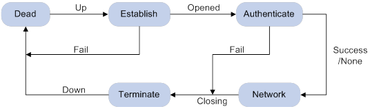
1. Initially, PPP is in Link Dead phase. After the physical layer goes up, PPP enters the Link Establishment phase (Establish).
2. In the Link Establishment phase, the LCP negotiation is performed. The LCP configuration options include Authentication-Protocol, Async-Control-Character-Map (ACCM), Maximum-Receive-Unit (MRU), Magic-Number, Protocol-Field-Compression (PFC), Address-and-Control-Field-Compression (ACFC), and MP.
? If the negotiation fails, LCP reports a Fail event, and PPP returns to the Dead phase.
? If the negotiation succeeds, LCP enters the Opened state and reports an Up event, indicating that the underlying layer link has been established. At this time, the PPP link is not established for the network layer, and network layer packets cannot be transmitted over the link.
3. If authentication is configured, the PPP link enters the Authentication phase, where PAP, CHAP, MS-CHAP, or MS-CHAP-V2 authentication is performed.
? If the client fails to pass the authentication, LCP reports a Fail event and enters the Link Termination phase. In this phase, the link is torn down and LCP goes down.
? If the client passes the authentication, LCP reports a Success event.
4. If a network layer protocol is configured, the PPP link enters the Network-Layer Protocol phase for NCP negotiation, such as IPCP negotiation and IPv6CP negotiation.
? If the NCP negotiation succeeds, the link goes up and becomes ready to carry negotiated network-layer protocol packets.
? If the NCP negotiation fails, NCP reports a Down event and enters the Link Termination phase.
If the interface is configured with an IP address, the IPCP negotiation is performed. IPCP configuration options include IP addresses and DNS server IP addresses. After the IPCP negotiation succeeds, the link can carry IP packets.
5. After the NCP negotiation is performed, the PPP link remains active until either of the following events occurs:
? Explicit LCP or NCP frames close the link.
? Some external events take place (for example, the intervention of a user).
For more information about PPP, see RFC 1661.
PPP authentication
PPP supports the following authentication methods:
· PAP—PAP is a two-way handshake authentication protocol using the username and password.
PAP sends username/password pairs in plain text over the network. If authentication packets are intercepted in transit, network security might be threatened. For this reason, it is suitable only for low-security environments.
· CHAP—CHAP is a three-way handshake authentication protocol.
CHAP transmits usernames but not passwords over the network. It transmits the result calculated from the password and random packet ID by using the MD5 algorithm. It is more secure than PAP. The authenticator may or may not be configured with a username. As a best practice, configure a username for the authenticator, which makes it easier for the peer to verify the identity of the authenticator.
· MS-CHAP—MS-CHAP is a three-way handshake authentication protocol.
MS-CHAP differs from CHAP as follows:
? MS-CHAP uses CHAP Algorithm 0x80.
? MS-CHAP provides authentication retry. If the peer fails authentication, it is allowed to retransmit authentication information to the authenticator for reauthentication. The authenticator allows a peer to retransmit a maximum of three times.
· MS-CHAP-V2—MS-CHAP-V2 is a three-way handshake authentication protocol.
MS-CHAP-V2 differs from CHAP as follows:
? MS-CHAP-V2 uses CHAP Algorithm 0x81.
? MS-CHAP-V2 provides two-way authentication by piggybacking a peer challenge on the Response packet and an authenticator response on the Acknowledge packet.
? MS-CHAP-V2 supports authentication retry. If the peer fails authentication, it is allowed to retransmit authentication information to the authenticator for reauthentication. The authenticator allows a peer to retransmit a maximum of three times.
? MS-CHAP-V2 supports password change. If the peer fails authentication because of an expired password, it will send the new password entered by the user to the authenticator for reauthentication.
PPP for IPv4
On IPv4 networks, PPP negotiates the IP address and DNS server address during IPCP negotiation.
IP address negotiation
IP address negotiation enables one end to assign an IP address to the other.
An interface can act as a client or a server during IP address negotiation:
· Client—Obtains an IP address from the server. Use the client mode when the device accesses the Internet through an ISP.
· Server—Assigns an IP address to the client. Before you configure the IP address of the server, you must perform one of the following tasks:
? Configure a local address pool and associate the pool with the ISP domain.
? Specify an IP address or an address pool for the client on the interface.
When IP address negotiation is enabled on a client, the server selects an IP address for the client in the following sequence:
1. If the AAA server configures an IP address or address pool for the client, the server selects that IP address or an IP address from the pool. The IP address or address pool is configured on the AAA server instead of the PPP server. For information about AAA, see Security Configuration Guide.
2. If an address pool is associated with the ISP domain used during client authentication, the server selects an IP address from the pool.
3. If an IP address or address pool is specified for the client on the interface of the server, the server selects that IP address or an IP address from that pool.
DNS server address negotiation
IPCP negotiation can determine the DNS server IP address.
When the device is connected to a host, configure the device as the server to assign the DNS server IP address to the host.
When the device is connected to an ISP access server, configure the device as the client. Then, the device can obtain the DNS server IP address from the ISP access server.
PPP for IPv6
On IPv6 networks, PPP negotiates only the IPv6 interface identifier instead of the IPv6 address and IPv6 DNS server address during IPv6CP negotiation.
IPv6 address assignment
PPP cannot negotiate the IPv6 address.
The client can get an IPv6 global unicast address through the following methods:
· Method 1—The client obtains an IPv6 prefix in an RA message. The client then generates an IPv6 global unicast address by combining the IPv6 prefix and the negotiated IPv6 interface identifier. The IPv6 prefix in the RA message is determined in the following sequence:
? IPv6 prefix authorized by AAA.
? RA prefix configured on the interface.
? Prefix of the IPv6 global unicast address configured on the interface.
For information about the ND protocol, see Layer 3—IP Services Configuration Guide.
· Method 2—The client requests an IPv6 global unicast address through DHCPv6. The server assigns an IPv6 address to the client from the address pool authorized by AAA. If no AAA-authorized address pool exists, DHCPv6 uses the address pool that matches the server's IPv6 address to assign an IPv6 address to the client. For information about DHCPv6, see Layer 3—IP Services Configuration Guide.
· Method 3—The client requests prefixes through DHCPv6 and assigns them to downstream hosts. The hosts then uses the prefixes to generate global IPv6 addresses. This method uses the same principle of selecting address pools as method 2.
The device can assign a host an IPv6 address in either of the following ways:
· When the host connects to the device directly or through a bridge device, the device can use method 1 or method 2.
· When the host accesses the device through a router, the device can use method 3 to assign an IPv6 prefix to the router. The router assigns the prefix to the host to generate an IPv6 global unicast address.
IPv6 DNS server address assignment
On IPv6 networks, two methods are available for the IPv6 DNS address assignment:
· AAA authorizes the IPv6 DNS address and assigns this address to the host through RA messages.
· The DHCPv6 client requests an IPv6 DNS address from the DHCPv6 server.
MP overview
Multilink PPP (MP) allows you to bind multiple PPP links into one MP bundle for increasing bandwidth. If a packet is larger than the minimum packet size for fragmentation, MP fragments the packet and distributes the fragments across multiple PPP links to the peer. The peer reassembles them into one packet and passes the packet to the network layer.
In addition to increasing bandwidth, MP also provides link-layer load sharing, which can implement backup. MP fragmentation can reduce transmission delay, especially on low-speed links.
MP is available to all physical or virtual interfaces with PPP encapsulation enabled, including serial, ISDN BRI/PRI, and PPPoX (PPPoE or PPPoA) interfaces. In MP configuration, as a best practice, include only one type of interfaces in an MP bundle.
Compatibility information
Feature and hardware compatibility
This feature is supported only on Layer 2 Ethernet ports on the following modules:
· AM.
· AS.
· ASE.
· BS.
· CE3.
· CPOS.
· E1.
· E1-F.
· POS.
· SAE.
· T1.
· T1-F.
Command and hardware compatibility
Commands and descriptions for centralized devices apply to the following routers:
· MSR810/810-W/810-W-DB/810-LM/810-W-LM/810-10-PoE/810-LM-HK/810-W-LM-HK/810-LMS/810-LUS.
· MSR2600-6-X1/2600-10-X1.
· MSR 2630.
· MSR3600-28/3600-51.
· MSR3600-28-SI/3600-51-SI.
· MSR3610-X1/3610-X1-DP/3610-X1-DC/3610-X1-DP-DC.
· MSR 3610/3620/3620-DP/3640/3660.
· MSR810-LM-GL/810-W-LM-GL/830-6EI-GL/830-10EI-GL/830-6HI-GL/830-10HI-GL/2600-6-X1-GL/3600-28-SI-GL.
Commands and descriptions for distributed devices apply to the following routers:
· MSR5620.
· MSR 5660.
· MSR 5680.
IPv6-related parameters are not supported on the following routers:
· MSR810/810-W/810-W-DB/810-LM/810-W-LM/810-10-PoE/810-LM-HK/810-W-LM-HK/810-LMS/810-LUS.
· MSR3600-28-SI/3600-51-SI.
Configuring PPP
PPP configuration task list
|
Tasks at a glance |
|
(Required.) Enabling PPP encapsulation on an interface |
|
(Optional.) Configuring PPP authentication |
|
(Optional.) Configuring the polling feature |
|
(Optional.) Configuring PPP negotiation |
|
(Optional.) Enabling IP header compression |
|
(Optional.) Enabling PPP link quality monitoring |
|
(Optional.) Enabling PPP accounting |
|
(Optional.) Configuring the nas-port-type attribute |
Enabling PPP encapsulation on an interface
|
Step |
Command |
Remarks |
|
1. Enter system view. |
system-view |
N/A |
|
interface interface-type interface-number |
N/A |
|
|
3. Enable PPP encapsulation on the interface. |
link-protocol ppp |
By default, all interfaces except Ethernet interfaces, VLAN interfaces, and ATM interfaces use PPP as the link layer protocol. |
Configuring PPP authentication
You can configure several authentication modes simultaneously. In LCP negotiation, the authenticator negotiates with the peer in the sequence of configured authentication modes until the LCP negotiation succeeds. If the response packet from the peer carries a recommended authentication mode, the authenticator directly uses the authentication mode if it finds the mode configured.
Configuring PAP authentication
To configure the authenticator:
|
Step |
Command |
Remarks |
|
1. Enter system view. |
system-view |
N/A |
|
2. Enter interface view. |
interface interface-type interface-number |
N/A |
|
3. Configure the authenticator to authenticate the peer by using PAP. |
ppp authentication-mode pap [ [ call-in ] domain { isp-name | default enable isp-name } ] |
By default, PPP authentication is disabled. |
|
4. Configure local or remote AAA authentication. |
For local AAA authentication, the username and password of the peer must be configured on the authenticator. For remote AAA authentication, the username and password of the peer must be configured on the remote AAA server. For more information about AAA authentication, see Security Configuration Guide. |
The username and password configured for the peer must be the same as those configured on the peer. |
To configure the peer:
|
Step |
Command |
Remarks |
|
1. Enter system view. |
system-view |
N/A |
|
2. Enter interface view. |
interface interface-type interface-number |
N/A |
|
3. Configure the PAP username and password sent from the peer to the authenticator when the peer is authenticated by the authenticator by using PAP. |
ppp pap local-user username password { cipher | simple } string |
By default, when being authenticated by the authenticator by using PAP, the peer sends null username and password to the authenticator. For security purposes, the password specified in plaintext form and ciphertext form will be stored in encrypted form. |
Configuring CHAP authentication
Depending on whether the authenticator is configured with a username, the configuration of CHAP authentication includes the following types:
· Configuring CHAP authentication when the authenticator name is configured
To configure the authenticator:
|
Step |
Command |
Remarks |
|
1. Enter system view. |
system-view |
N/A |
|
2. Enter interface view. |
interface interface-type interface-number |
N/A |
|
3. Configure the authenticator to authenticate the peer by using CHAP. |
ppp authentication-mode chap [ [ call-in ] domain { isp-name | default enable isp-name } ] |
By default, PPP authentication is disabled. |
|
4. Configure a username for the CHAP authenticator. |
ppp chap user username |
The default setting is null. The username you configure for the authenticator must be the same as the local username you configure for the authenticator on the peer. |
|
5. Configure local or remote AAA authentication. |
For local AAA authentication, the username and password of the peer must be configured on the authenticator. For remote AAA authentication, the username and password of the peer must be configured on the remote AAA server. For more information about AAA authentication, see Security Configuration Guide. |
The username configured for the peer must be the same as that configured on the peer. The passwords configured for the authenticator and peer must be the same. |
To configure the peer:
|
Step |
Command |
Remarks |
|
1. Enter system view. |
system-view |
N/A |
|
2. Enter interface view. |
interface interface-type interface-number |
N/A |
|
3. Configure a username for the CHAP peer. |
ppp chap user username |
The default setting is null. The username you configure for the peer here must be the same as the local username you configure for the peer on the authenticator. |
|
4. Configure local or remote AAA authentication. |
For local AAA authentication, the username and password of the authenticator must be configured on the peer. For remote AAA authentication, the username and password of the authenticator must be configured on the remote AAA server. For more information about AAA authentication, see Security Configuration Guide. |
The username configured for the authenticator must be the same as that configured on the authenticator. The passwords configured for the authenticator and peer must be the same. |
· Configuring CHAP authentication when no authenticator name is configured
To configure the authenticator:
|
Step |
Command |
Remarks |
|
1. Enter system view. |
system-view |
N/A |
|
2. Enter interface view. |
interface interface-type interface-number |
N/A |
|
3. Configure the authenticator to authenticate the peer by using CHAP. |
ppp authentication-mode chap [ [ call-in ] domain { isp-name | default enable isp-name } ] |
By default, PPP authentication is disabled. |
|
4. Configure local or remote AAA authentication. |
For local AAA authentication, the username and password of the peer must be configured on the authenticator. For remote AAA authentication, the username and password of the peer must be configured on the remote AAA server. For more information about AAA authentication, see Security Configuration Guide. |
The username configured for the peer must be the same as that configured on the peer. The passwords configured for the authenticator and peer must be the same. |
To configure the peer:
|
Step |
Command |
Remarks |
|
1. Enter system view. |
system-view |
N/A |
|
2. Enter interface view. |
interface interface-type interface-number |
N/A |
|
3. Configure a username for the CHAP peer. |
ppp chap user username |
The default setting is null. The username you configure on the peer must be the same as the local username you configure for the peer on the authenticator. |
|
4. Set the CHAP authentication password. |
ppp chap password { cipher | simple } string |
The default setting is null. The password you set on the peer must be the same as the password you set for the peer on the authenticator. For security purposes, the password specified in plaintext form and ciphertext form will be stored in encrypted form. |
Configuring MS-CHAP or MS-CHAP-V2 authentication
When you configure MS-CHAP or MS-CHAP-V2 authentication, follow these guidelines:
· The device can only act as an authenticator for MS-CHAP or MS-CHAP-V2 authentication.
· L2TP supports only MS-CHAP authentication.
· MS-CHAP-V2 authentication supports password change only when using RADIUS.
· As a best practice, do not set the authentication method for PPP users to none when MS-CHAP-V2 authentication is used.
To configure MS-CHAP or MS-CHAP-V2 authentication when the authenticator name is configured:
|
Step |
Command |
Remarks |
|
1. Enter system view. |
system-view |
N/A |
|
2. Enter interface view. |
interface interface-type interface-number |
N/A |
|
3. Configure the authenticator to authenticate the peer by using MS-CHAP or MS-CHAP-V2. |
ppp authentication-mode { ms-chap | ms-chap-v2 } [ [ call-in ] domain { isp-name | default enable isp-name } ] |
By default, PPP authentication is disabled. |
|
4. Configure a username for the MS-CHAP or MS-CHAP-V2 authenticator. |
ppp chap user username |
The username for the authenticator must be the same on the local and peer devices. |
|
5. Configure local or remote AAA authentication. |
For local AAA authentication, the username and password of the peer must be configured on the authenticator. For remote AAA authentication, the username and password of the peer must be configured on the remote AAA server. For more information about AAA authentication, see Security Configuration Guide. |
The username and password of the peer configured on the authenticator or remote AAA server must be the same as those configured on the peer. |
To configure MS-CHAP or MS-CHAP-V2 authentication when no authenticator name is configured:
|
Step |
Command |
Remarks |
|
1. Enter system view. |
system-view |
N/A |
|
2. Enter interface view. |
interface interface-type interface-number |
N/A |
|
3. Configure the authenticator to authenticate the peer by using MS-CHAP or MS-CHAP-V2. |
ppp authentication-mode { ms-chap | ms-chap-v2 } [ [ call-in ] domain { isp-name | default enable isp-name } ] |
By default, PPP authentication is disabled. |
|
4. Configure local or remote AAA authentication. |
For local AAA authentication, the username and password of the peer must be configured on the authenticator. For remote AAA authentication, the username and password of the peer must be configured on the remote AAA server. For more information about AAA authentication, see Security Configuration Guide. |
The username and password of the peer configured on the authenticator or remote AAA server must be the same as those configured on the peer. |
Configuring the polling feature
The polling feature checks PPP link state.
On an interface that uses PPP encapsulation, the link layer sends keepalives at keepalive intervals to detect the availability of the peer. If the interface receives no response to keepalives when the keepalive retry limit is reached, it tears down the link and reports a link layer down event.
To set the keepalive retry limit, use the timer-hold retry command.
On a slow link, increase the keepalive interval to prevent false shutdown of the interface. This situation might occur when keepalives are delayed because a large packet is being transmitted on the link.
The keepalive interval must be smaller than the negotiation timeout time.
To disable sending of keepalives, set the keepalive interval to 0. In this case, the interface can respond to keepalive packets from the peer.
To configure the polling feature:
|
Step |
Command |
Remarks |
|
1. Enter system view. |
system-view |
N/A |
|
2. Enter interface view. |
interface interface-type interface-number |
N/A |
|
3. Set the keepalive interval. |
timer-hold seconds |
The default setting is 10 seconds. |
|
4. Set the keepalive retry limit. |
timer-hold retry retries |
The default setting is 5. |
Configuring PPP negotiation
PPP negotiation includes the following parameters:
· Negotiation timeout time.
· IP address negotiation.
· IP segment match.
· DNS server IP address negotiation.
· ACCM negotiation.
· ACFC negotiation.
· PFC negotiation.
Configuring the PPP negotiation timeout time
The device starts the PPP negotiation timeout timer after sending a packet. If no response is received before the timer expires, the device sends the packet again.
If two ends of a PPP link vary greatly in the LCP negotiation packet processing rate, configure the LCP negotiation delay timer on the end with a higher processing rate. The LCP negotiation delay timer prevents frequent LCP negotiation packet retransmissions. After the physical layer comes up, PPP starts LCP negotiation when the delay timer expires. If PPP receives LCP negotiation packets before the delay timer expires, it starts LCP negotiation immediately.
To configure the PPP negotiation timeout time:
|
Step |
Command |
Remarks |
|
1. Enter system view. |
system-view |
N/A |
|
2. Enter interface view. |
interface interface-type interface-number |
N/A |
|
3. Configure the negotiation timeout time. |
ppp timer negotiate seconds |
The default setting is 3 seconds. |
|
4. (Optional.) Configure the LCP negotiation delay timer. |
ppp lcp delay milliseconds |
By default, PPP starts LCP negotiation immediately after the physical layer is up. |
Configuring IP address negotiation
To configure the device as the client:
|
Step |
Command |
Remarks |
|
1. Enter system view. |
system-view |
N/A |
|
2. Enter interface view. |
interface interface-type interface-number |
N/A |
|
3. Enable IP address negotiation. |
ip address ppp-negotiate |
By default, IP address negotiation is not enabled. If you execute the ip address ppp-negotiate and ip address commands multiple times, the most recent configuration takes effect. For more information about the ip address command, see Layer 3—IP Services Command Reference. |
Configure the server to assign an IP address to a client by using the following methods:
· Method 1: Specify an IP address for the client on the server interface.
· Method 2: Specify a PPP or DHCP address pool on the server interface.
· Method 3: Associate a PPP or DHCP address pool with an ISP domain.
For clients requiring no authentication, you can use either method 1 or method 2. When both method 1 and method 2 are used, the most recent configuration takes effect.
For clients requiring authentication, you can use one or more of the three methods. When multiple methods are configured, method 3 takes precedence over method 1 or method 2. When both method 1 and method 2 are used, the most recent configuration takes effect.
PPP supports IP address assignment from a PPP or DHCP address pool. If you use a pool name that identifies both a PPP address pool and a DHCP address pool, the system uses the PPP address pool. When assigning IP address to users through a PPP address pool, make sure the PPP address pool excludes the gateway IP address of the PPP address pool.
To configure the device as the server (Method 1):
|
Step |
Command |
Remarks |
|
1. Enter system view. |
system-view |
N/A |
|
2. Enter interface view. |
interface interface-type interface-number |
N/A |
|
3. Configure the interface to assign an IP address to the peer. |
remote address ip-address |
By default, an interface does not assign an IP address to the peer. |
|
4. Configure an IP address for the interface. |
ip address ip-address |
By default, no IP address is configured on an interface. |
To configure the device as the server (Method 2: Specify a PPP address pool):
|
Step |
Command |
Remarks |
|
1. Enter system view. |
system-view |
N/A |
|
2. Configure a PPP address pool. |
ip pool pool-name start-ip-address [ end-ip-address ] [ group group-name ] |
By default, no PPP address pool is configured. |
|
3. (Optional.) Configure a gateway address for the PPP address pool. |
ip pool pool-name gateway ip-address [ vpn-instance vpn-instance-name ] |
By default, the PPP address pool is not configured with a gateway address. |
|
4. (Optional.) Configure a PPP address pool route. |
ppp ip-pool route ip-address { mask-length | mask } [ vpn-instance vpn-instance-name ] |
By default, no PPP address pool route exists. The destination network of the PPP address pool route must include the PPP address pool. |
|
5. Enter interface view. |
interface interface-type interface-number |
N/A |
|
6. Configure the interface to assign an IP address from the configured PPP address pool to the peer. |
remote address pool pool-name |
By default, an interface does not assign an IP address to the peer. |
|
7. Configure an IP address for the interface. |
ip address ip-address |
By default, no IP address is configured on an interface. |
To configure the device as the server (Method 2: Specify a DHCP address pool):
|
Step |
Command |
Remarks |
|
1. Enter system view. |
system-view |
N/A |
|
2. Configure DHCP. |
· If the server acts as a DHCP server, configure the DHCP server and a DHCP address pool on the server. · If the server acts as a DHCP relay agent, configure the DHCP relay agent on the server, and configure a DHCP address pool on the remote DHCP server. In addition, you must enable the DHCP relay agent to record relay entries, and configure a DHCP relay address pool. |
For information about configuring DHCP, see Layer 3 IP Services Configuration Guide. |
|
3. Enter interface view. |
interface interface-type interface-number |
N/A |
|
4. Configure the interface to assign an IP address from the configured DHCP address pool to the peer. |
remote address pool pool-name |
By default, an interface does not assign an IP address to the peer. |
|
5. Configure an IP address for the interface. |
ip address ip-address |
By default, no IP address is configured on an interface. |
To configure the device as the server (Method 3: Associate a PPP address pool with an ISP domain):
|
Step |
Command |
Remarks |
|
1. Enter system view. |
system-view |
N/A |
|
2. Configure a PPP address pool. |
ip pool pool-name start-ip-address [ end-ip-address ] [ group group-name ] |
By default, no PPP address pool is configured. |
|
3. (Optional.) Configure a gateway address for the PPP address pool. |
ip pool pool-name gateway ip-address [ vpn-instance vpn-instance-name ] |
By default, the PPP address pool is not configured with a gateway address. |
|
4. (Optional.) Configure a PPP address pool route. |
ppp ip-pool route ip-address { mask-length | mask } [ vpn-instance vpn-instance-name ] |
By default, no PPP address pool route exists. The destination network of the PPP address pool route must include the PPP address pool. |
|
5. Enter ISP domain view. |
domain isp-name |
N/A |
|
6. Associate the ISP domain with the configured PPP address pool for address assignment. |
authorization-attribute ip-pool pool-name |
By default, no PPP address pool is associated. For more information about this command, see Security Command Reference. |
|
7. Return to system view. |
quit |
N/A |
|
8. Enter interface view. |
interface interface-type interface-number |
N/A |
|
9. Configure an IP address for the interface. |
ip address ip-address |
By default, no IP address is configured on an interface. |
To configure the device as the server (Method 3: Associate a DHCP address pool with an ISP domain):
|
Step |
Command |
Remarks |
|
1. Enter system view. |
system-view |
N/A |
|
2. Configure DHCP. |
· If the server acts as a DHCP server, configure the DHCP server and a DHCP address pool on the server. · If the server acts as a DHCP relay agent, configure the DHCP relay agent on the server, and configure a DHCP address pool on the remote DHCP server. In addition, you must enable the DHCP relay agent to record relay entries, and configure a DHCP relay address pool. |
For information about configuring DHCP, see Layer 3 IP Services Configuration Guide. |
|
3. Enter ISP domain view. |
domain isp-name |
N/A |
|
4. Associate the ISP domain with the configured DHCP address pool for address assignment. |
authorization-attribute ip-pool pool-name |
By default, no DHCP address pool is associated. For more information about this command, see Security Command Reference. |
|
5. Return to system view. |
quit |
N/A |
|
6. Enter interface view. |
interface interface-type interface-number |
N/A |
|
7. Configure an IP address for the interface. |
ip address ip-address |
By default, no IP address is configured on an interface. |
Enabling IP segment match
This feature enables the local interface to check whether its IP address and the IP address of the remote interface are in the same network segment. If they are not, IPCP negotiation fails.
To enable IP segment match:
|
Step |
Command |
Remarks |
|
1. Enter system view. |
system-view |
N/A |
|
2. Enter interface view. |
interface interface-type interface-number |
N/A |
|
3. Enable IP segment match. |
ppp ipcp remote-address match |
By default, this feature is disabled. |
Configuring DNS server IP address negotiation
Configure DNS server settings depending on the role of your device in PPP negotiation.
· Configuring the local end as the client
During PPP negotiation, the server will assign a DNS server IP address only for a client configured with the ppp ipcp dns request command. For some special devices to forcibly assign DNS server IP addresses to clients that do not initiate requests, configure the ppp ipcp dns admit-any command on these devices.
To configure the local end as the client:
|
Step |
Command |
Remarks |
|
1. Enter system view. |
system-view |
N/A |
|
2. Enter interface view. |
interface interface-type interface-number |
N/A |
|
3. Enable the device to request the peer for a DNS server IP address. |
ppp ipcp dns request |
By default, a client does not request its peer for a DNS server IP address. |
|
4. Configure the device to accept the DNS server IP addresses assigned by the peer even though it does not request the peer for the DNS server IP addresses. |
ppp ipcp dns admit-any |
By default, a device does not accept the DNS server IP addresses assigned by the peer if it does not request the peer for the DNS server IP addresses. This command is not necessary if the ppp ipcp dns request command is configured. |
· Configuring the local end as the server
|
Step |
Command |
Remarks |
|
1. Enter system view. |
system-view |
N/A |
|
2. Enter interface view. |
interface interface-type interface-number |
N/A |
|
3. Specify the primary and secondary DNS server IP addresses to be allocated to the peer in PPP negotiation. |
ppp ipcp dns primary-dns-address [ secondary-dns-address ] |
By default, a device does not allocate DNS server IP addresses to its peer if the peer does not request them. |
Configuring ACCM negotiation
PPP uses the escape mechanism on asynchronous links to avoid treating payload characters as control characters. The escape mechanism converts all one-byte asynchronous control characters into two-byte characters. This mechanism increases the size of asynchronous control characters and reduces the payload size.
The ACCM configuration option provides a method to negotiate with the peer of the local control characters, which must be converted on asynchronous links. The ACCM field contains 32 bits numbered 1 to 32 from left to right. Each bit corresponds to an asynchronous control character numbered the same. If the value of a bit is 0, the system does not convert the corresponding asynchronous control character. If the value of a bit is 1, the system converts the corresponding asynchronous control character by prefacing it with a backslash (\). For example, if the value of the bit numbered 19 is 0, the asynchronous control character numbered 19 (DC3, Control-S) will be sent without being converted.
ACCM negotiation is implemented at the LCP negotiation stage. After ACCM negotiation is completed, the peer converts asynchronous control characters according to the Async Control Character Mappings when sending packets.
By default, the ACCM field takes the value of 0x000A0000. To increase the payload size on low-rate links, set the ACCM field to 0x0 so the system does not convert asynchronous control characters.
To configure ACCM negotiation:
|
Step |
Command |
Remarks |
|
1. Enter system view. |
system-view |
N/A |
|
2. Enter interface view. |
interface interface-type interface-number |
N/A |
|
3. Configure the ACCM value. |
ppp accm hex-number |
By default, the ACCM value is 0x000A0000. The ACCM negotiation option applies only to asynchronous links. |
Configuring ACFC negotiation
PPP can compress the address and control fields of PPP packets to increase the payload size.
ACFC negotiation notifies the peer that the local end can receive packets carrying compressed address and control fields.
ACFC negotiation is implemented at the LCP negotiation stage. After the ACFC negotiation succeeds, PPP does not include the address and control fields in non-LCP packets. To ensure successful LCP negotiation, PPP does not apply the compression to LCP packets.
As a best practice, use the ACFC configuration option on low-speed links.
To configure the local end to send ACFC requests:
|
Step |
Command |
Remarks |
|
1. Enter system view. |
system-view |
N/A |
|
2. Enter interface view. |
interface interface-type interface-number |
N/A |
|
3. Configure the local end to send ACFC requests by including the ACFC option in outbound LCP negotiation requests. |
ppp acfc local request |
By default, the local end does not include the ACFC option in outbound LCP negotiation requests. |
To configure the local end to reject ACFC requests received from the peer:
|
Step |
Command |
Remarks |
|
1. Enter system view. |
system-view |
N/A |
|
2. Enter interface view. |
interface interface-type interface-number |
N/A |
|
3. Configure the local end to reject ACFC requests received from the peer. |
ppp acfc remote-reject |
By default, the local end accepts the ACFC requests from the remote peer, and performs ACFC on frames sent to the peer. |
Configuring PFC negotiation
PPP can compress the protocol field of PPP packets from 2 bytes to 1 byte to increase the payload size.
PFC negotiation notifies the peer that the local end can receive packets with a single-byte protocol field.
PFC negotiation is implemented at the LCP negotiation stage. After PFC negotiation is completed, the device compresses the protocol field of sent non-LCP packets. If the first eight bits of the protocol field are all zeros, the device does not add those bits into the packet. To ensure successful LCP negotiation, PPP does not apply the compression to LCP packets.
As a best practice, use this configuration option on low-speed links.
To configure the local end to send PFC requests:
|
Step |
Command |
Remarks |
|
1. Enter system view. |
system-view |
N/A |
|
2. Enter interface view. |
interface interface-type interface-number |
N/A |
|
3. Configure the local end to send PFC requests by including the PFC option in outbound LCP negotiation requests. |
ppp pfc local request |
By default, the local end does not include the PFC option in outbound LCP negotiation requests. |
To configure the local end to reject PFC requests received from the peer:
|
Step |
Command |
Remarks |
|
1. Enter system view. |
system-view |
N/A |
|
2. Enter interface view. |
interface interface-type interface-number |
N/A |
|
3. Configure the local end to reject PFC requests received from the peer. |
ppp pfc remote-reject |
By default, the device accepts PFC requests received from the peer, and performs PFC on frames sent to the peer. |
Enabling IP header compression
IP header compression (IPHC) compresses packet headers to speed up packet transmission. IPHC is often used for voice communications over low-speed links.
IPHC provides the following compression features:
· RTP header compression—Compresses the IP header, UDP header, and RTP header of an RTP packet, which have a total length of 40 bytes.
· TCP header compression—Compresses the IP header and TCP header of a TCP packet, which have a total length of 40 bytes.
To use IPHC, you must enable it on both sides of a PPP link.
Enabling or disabling IPHC on a VT, dialer, or ISDN interface does not immediately take effect. You must execute the shutdown and undo shutdown commands on the interface or the bound physical interface to apply the new setting.
After you enable IPHC, you can configure the maximum number of connections for RTP or TCP header compression. The configuration takes effect after you execute the shutdown and undo shutdown command on the interface. The configuration is removed after IPHC is disabled.
To configure IPHC:
|
Step |
Command |
Remarks |
|
1. Enter system view. |
system-view |
N/A |
|
2. Enter interface view. |
interface interface-type interface-number |
N/A |
|
3. Enable IP header compression. |
ppp compression iphc enable [ nonstandard ] |
By default, IP header compression is disabled. The nonstandard option must be specified when the device communicates with a non-H3C device. When the nonstandard keyword is specified, only RTP header compression is supported and TCP header compression is not supported. |
|
4. Set the maximum number of connections for which an interface can perform RTP header compression. |
ppp compression iphc rtp-connections number |
The default setting is 16. |
|
5. Set the maximum number of connections for which an interface can perform TCP header compression. |
ppp compression iphc tcp-connections number |
The default setting is 16. |
Enabling PPP link quality monitoring
PPP link quality monitoring (LQM) monitors the quality (packet loss ratio and packet error ratio) of PPP links (including those in MP bundles) in real time.
If PPP LQM is not enabled, each end of a PPP link periodically sends keepalives to its peer. If PPP LQM is enabled, Link Quality Reports (LQRs) packets replace keepalives to monitor the link.
The system uses received LQR packets to measure the link quality. If two consecutive measured results are below the close-percentage, the system shuts down the link. Then the system measures the link quality at an interval that is ten times the LQR interval. If three consecutive measured results are higher than the PPP LQM resume-percentage, the system brings up the link.
A shut-down link must experience a minimum of 30 keepalive intervals before it can come up again. As a best practice, do not set the keepalive interval to a large value.
If you enable PPP LQM on both sides of a PPP link, make sure both sides have the same PPP LQM settings. Typically, there is no need to enable PPP LQM on both sides of a PPP link.
As a best practice, do not enable PPP LQM on a DDR dial-up link because DDR tears the link down when the link is closed by LQM. Then LQM cannot send LQR packets to resume the link.
To enable PPP LQM:
|
Step |
Command |
Remarks |
|
1. Enter system view. |
system-view |
N/A |
|
2. Enter interface view. |
interface interface-type interface-number |
N/A |
|
3. Enable PPP LQM. |
ppp lqm close-percentage close-percentage [ resume-percentage resume-percentage ] |
By default, PPP LQM is disabled. |
|
4. Configure the interface to periodically send LCP echo packets when LQM detects a low quality link. |
ppp lqm lcp-echo [ packet size ] [ interval interval ] |
By default, the interface does not send LCP echo packets when LQM detects a low quality link. |
Enabling PPP accounting
PPP accounting collects PPP statistics, including the numbers of received and sent PPP packets and bytes. AAA can use the PPP statistics for accounting. For more information about AAA, see Security Configuration Guide.
To enable PPP accounting:
|
Step |
Command |
Remarks |
|
1. Enter system view. |
system-view |
N/A |
|
2. Enter interface view. |
interface interface-type interface-number |
N/A |
|
3. Enable PPP accounting. |
ppp account-statistics enable [ acl { acl-number | name acl-name } ] |
By default, PPP accounting is disabled. |
Configuring the nas-port-type attribute
The nas-port-type attribute is used for RADIUS authentication and accounting. For information about the nas-port-type attribute, see RFC 2865.
To configure the nas-port-type attribute:
|
Step |
Command |
Remarks |
|
1. Enter system view. |
system-view |
N/A |
|
2. Enter VT interface view. |
interface virtual-template number |
N/A |
|
3. Configure the nas-port-type attribute. |
nas-port-type { 802.11 | adsl-cap | adsl-dmt | async | cable | ethernet | g.3-fax | hdlc | idsl | isdn-async-v110 | isdn-async-v120 | isdn-sync | piafs | sdsl | sync | virtual | wireless-other | x.25 | x.75 | xdsl } |
By default, the nas-port-type attribute is determined by the service type and link type of the PPP user (see Table 1). |
Table 1 Default nas-port-type attribute
|
Service type |
Link type |
Nas-port-type attribute |
|
PPPoE |
Layer 3 virtual Ethernet interface |
xdsl |
|
Other interfaces |
ethernet |
|
|
PPPoA |
Any |
xdsl |
|
L2TP |
Any |
virtual |
Configuring MP
MP supports binding interfaces on the same LPU rather than on different LPUs.
You can configure MP by using virtual template (VT) or MP-group interfaces:
· VT interfaces—VT interfaces are used to configure VA interfaces. After binding multiple PPP links into an MP link, you must create a VA interface for the MP link to exchange data with the peers.
VT interfaces support authentication. The device finds a VT interface for a peer according to the username provided by the peer. The device then creates a bundle that corresponds to an MP link based on the VT settings.
MP can create multiple bundles using the same VT interface. Each bundle is an MP link. From the perspective of the network layer, these links form a point-to-multipoint topology.
The system uses usernames or terminal descriptors to distinguish multiple MP links under one VT interface. The following binding modes are available:
? authentication—Binds links by using authentication usernames. Each authentication username corresponds to one bundle. The username is sent by the peer to the authenticator in PAP, CHAP, MS-CHAP, or MS-CHAP-V2 authentication.
? descriptor—Binds links by using descriptors. Each descriptor corresponds to one bundle. A descriptor is received from the peer during LCP negotiation and uniquely identifies the peer.
? both—Binds links by using both the authentication username and descriptor.
· MP-group interfaces—MP-group interfaces are intended only for MP. On an MP-group interface, only one bundle is allowed, and links cannot be bundled according to the peer descriptor. Compared with VT interfaces, the configuration of MP-group interfaces is more efficient and easier to configure and understand.
MP configuration task list
|
Tasks at a glance |
|
(Required.) Perform either task: |
|
(Optional.) Configuring short sequence number header format negotiation |
|
(Optional.) Configuring the MP endpoint descriptor |
|
(Optional.) Configuring LFI |
Configuring MP by using a VT interface
You can use either of the following methods to configure MP by using a VT interface:
· Bind physical interfaces to the VT interface by using the ppp mp virtual-template command.
? If authentication is not configured, the system binds links according to the descriptor of the peer.
? If authentication is configured, the system binds links according to the username, the descriptor of the peer, or both.
· Associate a username with the VT interface. After the user passes authentication, the system finds the VT interface associated with the username and bundles links according to the username and the descriptor of the peer. To ensure a successful link negotiation, configure the ppp mp command and two-way authentication (PAP, CHAP, MS-CHAP, or MS-CHAP-V2) on the bundled interfaces.
When you configure MP by using a VT interface, follow these guidelines:
· If you execute the ppp mp and ppp mp virtual-template commands multiple times, the most recent configuration takes effect.
· You must use the same method to configure the interfaces to be bundled .
· To use one-way authentication, associate physical interfaces with a VT interface on one end and associate a username with the VT interface on the other end.
· Configure a VT interface to provide only one service, such as MP, L2TP, or PPPoE.
Configuring MP by using a VT interface
|
Step |
Command |
Remarks |
|
1. Enter system view. |
system-view |
N/A |
|
2. Create a VT interface and enter its view. |
interface virtual-template number |
If the VT interface already exists, you enter its view directly. |
|
3. (Optional.) Set the interface description. |
description text |
By default, the description of a VT interface is interface name Interface, for example, Virtual-Template1 Interface. |
|
4. Set the keepalive interval. |
timer-hold seconds |
The default setting is 10 seconds. |
|
5. Set the keepalive retry limit. |
timer-hold retry retries |
The default setting is 5. |
|
6. Set the MTU size of the interface. |
mtu size |
The default setting is 1500 bytes. |
|
7. Set the expected bandwidth of the VT interface. |
bandwidth bandwidth-value |
By default, the expected bandwidth (in kbps) is the interface baud rate divided by 1000. |
|
8. (Optional.) Specify a primary traffic processing slot for the interface. |
·
Distributed devices in standalone mode/centralized
devices in IRF mode: ·
Distributed devices in IRF mode: |
By default, no primary traffic processing slot is specified for an interface. |
|
9. (Optional.) Specify a backup traffic processing slot for the interface. |
·
Distributed devices in standalone mode/centralized
devices in IRF mode: ·
Distributed devices in IRF mode: |
By default, no backup traffic processing slot is specified for an interface. |
|
10. (Optional.) Restore the default settings for the VT interface. |
default |
N/A |
|
11. Return to system view. |
quit |
N/A |
|
12. Associate a physical interface or a username with the VT interface. |
· (Method 1) Bind a physical interface to the VT interface: a.
Enter interface view: b. Bind the interface to the specified VT interface, and enable MP
for the interface: c. (Optional.) Configure PPP authentication (see "Configuring PPP authentication.") · (Method 2) Associate a username to the VT interface: d. Associate a VT interface to a username: e.
Enter interface view: f.
Enable MP for the interface: g. Configure PPP authentication (see "Configuring PPP authentication.") |
By default, a physical interface is enabled with PPP and not bound to any VT interface. PPP authentication does not affect MP when Method 1 is used. By default, a VT interface is not bound to any username. |
|
13. Configure other MP parameters. |
N/A |
Configuring other optional parameters
|
Step |
Command |
Remarks |
|
1. Enter system view. |
system-view |
N/A |
|
2. Enter MP VT interface or dialer interface view. |
interface { dialer | virtual-template } number |
For more information about configuring MP parameters in dialer interface view, see "Configuring DDR." |
|
3. Set the binding mode. |
ppp mp binding-mode { authentication | both | descriptor } |
By default, both the username and the descriptor are used for MP binding. |
|
4. (Optional.) Set the maximum number of links in an MP bundle. |
ppp mp max-bind max-bind-num |
The default setting is 16. |
|
5. (Optional.) Set the minimum number of links in an MP bundle. |
ppp mp min-bind min-bind-num |
The default setting is 0, which means MP dialup depends on traffic detection. This command is available only in dialer interface view. The minimum number cannot be greater than the maximum number set with the ppp mp max-bind command. |
|
6. Set the minimum size of MP fragments. |
ppp mp min-fragment size |
The default setting is 128 bytes. |
|
7. Configure the MP sort buffer size factor. |
ppp mp sort-buffer-size size |
The default setting is 1. |
|
8. (Optional.) Configure the timer for MP to wait for the expected fragment. |
ppp mp timer lost-fragment seconds |
By default, the timer is 30 seconds. |
|
9. (Optional.) Disable MP fragmentation. |
ppp mp fragment disable |
By default, MP fragmentation is enabled. When this command is configured on an interface, the ppp mp lfi enable and ppp mp min-fragment commands do not take effect on the interface. |
Configuring MP through an MP-group interface
|
Step |
Command |
Remarks |
|
1. Enter system view. |
system-view |
N/A |
|
2. Create an MP-group interface and enter its view. |
interface mp-group mp-number |
If the MP-group interface already exists, you enter its view directly. |
|
3. (Optional.) Set the maximum number of links in an MP bundle. |
ppp mp max-bind max-bind-num |
The default setting is 16. For this command to take effect on an MP bundle, you must re-enable all the physical interfaces in the MP bundle by executing the shutdown command and then the undo shutdown command. |
|
4. Set the minimum MP packet size for fragmentation. |
ppp mp min-fragment size |
The default setting is 128 bytes. |
|
5. Configure the MP sort buffer size factor. |
ppp mp sort-buffer-size size |
The default setting is 1. |
|
6. (Optional.) Start the timer for waiting for the expected fragment. |
ppp mp timer lost-fragment seconds |
By default, the timer is not started. |
|
7. (Optional.) Disable MP fragmentation. |
ppp mp fragment disable |
By default, MP fragmentation is enabled. After you configure this command on an interface, the settings configured with the ppp mp lfi enable and ppp mp min-fragment commands do not take effect on the interface. |
|
8. (Optional.) Set the interface description. |
description text |
Optional. The default setting is interface name Interface, for example, MP-group3 Interface. |
|
9. Set the keepalive interval. |
timer-hold seconds |
The default setting is 10 seconds. |
|
10. Set the keepalive retry limit. |
timer-hold retry retries |
The default setting is 5. |
|
11. Set the MTU size of the interface. |
mtu size |
The default setting is 1500 bytes. |
|
12. Set the expected bandwidth of the interface. |
bandwidth bandwidth-value |
By default, the expected bandwidth (in kbps) is the interface baud rate divided by 1000. |
|
13. (Optional.) Restore the default settings for the interface. |
default |
N/A |
|
14. Bring up the interface. |
undo shutdown |
By default, an interface is up. |
|
15. Return to system view. |
quit |
N/A |
|
16. Enter interface view. |
interface interface-type interface-number |
N/A |
|
17. Assign the interface to a specified MP-group interface, and enable MP for the interface. |
ppp mp mp-group mp-number |
By default, an interface is enabled with PPP. |
Configuring short sequence number header format negotiation
By default, an MP bundle receives and transmits fragments with long sequence numbers.
· To receive fragments with short sequence numbers, the local end should request the peer to transmit short sequence numbers during LCP negotiation. After the negotiation succeeds, the peer transmits fragments with short sequence numbers.
· To transmit fragments with short sequence numbers, the local end should ask the peer to send a request for receiving short sequence numbers during LCP negotiation. After the negotiation succeeds, the local end transmits fragments with short sequence numbers.
The sequence number format (long or short) of an MP bundle depends on the configuration of the first channel joining the MP bundle.
To negotiate the use of short sequence numbers on a dialer MP bundle, configure the command on the dialer interfaces and the ISDN D channels. To negotiate the use of short sequence numbers on a common MP bundle, use the command on all its channels. Note that the command will cause PPP re-negotiation.
To configure short sequence number header format negotiation for MP:
|
Step |
Command |
Remarks |
|
1. Enter system view |
system-view |
N/A |
|
2. Enter interface view. |
interface interface-type interface-number |
N/A |
|
3. Trigger MP short sequence number header negotiation, specifying that the interface receive fragments with short sequence numbers after the negotiation succeeds. |
ppp mp short-sequence |
By default, long sequence number header format negotiation is performed. |
Configuring the MP endpoint descriptor
When MP is configured by using a VT interface, an MP endpoint makes link binding decisions based on the remote endpoint descriptors. It assigns the links that receive the same endpoint descriptor to the same bundle. To avoid incorrect link binding on a VT interface, make sure the link descriptors used by different devices are unique. You must re-configure an endpoint descriptor for a device if the default endpoint descriptor (device name) cannot uniquely identify the MP bundle at the remote end.
When MP is configured by using an MP-group interface, the negotiating endpoints do not base their binding decisions on the endpoint descriptor. By default, the endpoint descriptor of an interface in an MP-group is the MP-group interface name. When you configure an endpoint descriptor for the interface, the configured MP endpoint descriptor takes effect.
If the endpoint descriptor exceeds 20 bytes, the first 20 bytes are taken as the endpoint descriptor.
To configure the MP endpoint descriptor of an interface for LCP negotiation:
|
Step |
Command |
Remarks |
|
1. Enter system view. |
system-view |
N/A |
|
2. Enter interface view. |
interface interface-type interface-number |
N/A |
|
3. Configure the MP endpoint descriptor. |
ppp mp endpoint endpoint |
N/A |
Configuring LFI
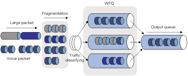
Real-time packets, such as Telnet and VoIP packets, might be blocked or delayed on a low-speed interface.
To reduce delays and jitters on low-speed links, LFI fragments large packets into small fragments. The fragments are reassembled at the destination.
Figure 2 illustrates the LFI process. When large packets and small voice packets arrive at a WFQ-enabled interface, LFI performs the following operations:
· Fragments the large packets into small fragments.
· Adds the fragments to the queues along with the voice packets.
To configure LFI:
|
Step |
Command |
Remarks |
|
1. Enter system view. |
system-view |
N/A |
|
2. Enter VT interface, MP-group interface, or dialer interface view. |
interface { dialer | mp-group | virtual-template } mp-number |
N/A |
|
3. Enable LFI. |
ppp mp lfi enable |
By default, LFI is disabled. Disabling LFI also removes the user-configured settings of the maximum LFI fragment delay and size. |
|
4. Set the maximum LFI fragment transmission delay and the maximum LFI fragment size (in bytes). |
· ppp mp lfi delay-per-frag time · ppp mp lfi size-per-frag size |
By default, the maximum LFI fragment transmission delay is 10 ms, and the maximum LFI fragment size is the expected bandwidth of the interface times the maximum delay divided by 8. |
Displaying and maintaining PPP and MP
Execute display commands in any view and reset commands in user view.
|
Task |
Command |
|
Display information about PPP access users. |
display ppp access-user { interface interface-type interface-number [ count ] | ip-address ip-address | ipv6-address ipv6-address | username user-name | user-type { lac | lns | pppoa | pppoe } [ count ] } |
|
Display PPP address pools. |
display ip pool [ pool-name ] [ group group-name ] |
|
Display IPHC statistics. |
display ppp compression iphc { rtp | tcp } [ interface interface-type interface-number ] |
|
Display information about VT interfaces. |
display interface [ virtual-template [ interface-number ] ] [ brief [ description | down ] ] |
|
Display information about VA interfaces on a VT interface. |
display interface [ virtual-access [ interface-number ] ] [ brief [ description | down ] ] |
|
Display information about one or all MP-group interfaces. |
display interface [ mp-group [ interface-number ] ] [ brief [ description | down ] ] |
|
Display MP information. |
display ppp mp [ interface interface-type interface-number ] |
|
Clear IPHC statistics. |
reset ppp compression iphc [ rtp | tcp ] [ interface interface-type interface-number ] |
|
Log off a PPP user. |
reset ppp access-user { ip-address ipv4-ip-address [ vpn-instance ipv4-vpn-instance-name ] | ipv6-address ipv6-address [ vpn-instance ipv6-vpn-instance-name ] | username user-name } |
|
Clear the statistics for VA interfaces. |
reset counters interface [ virtual-access [ interface-number ] ] |
|
Clear the statistics for MP-group interfaces. |
reset counters interface [ mp-group [ interface-number ] ] |
PPP and MP configuration examples
One-way PAP authentication configuration example
Network requirements
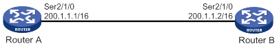
As shown in Figure 3, configure Router A to authenticate Router B by using PAP, but Router B not to authenticate Router A.
Configuration procedure
1. Configure Router A:
# Create a user account for Router B.
<RouterA> system-view
[RouterA] local-user userb class network
# Set a password for the user account.
[RouterA-luser-network-userb] password simple passb
# Set the service type of the user account to PPP.
[RouterA-luser-network-userb] service-type ppp
[RouterA-luser-network-userb] quit
# Enable PPP encapsulation on Serial 2/1/0. By default, an interface uses PPP encapsulation.
[RouterA] interface serial 2/1/0
[RouterA-Serial2/1/0] link-protocol ppp
# Set the authentication mode to PAP.
[RouterA-Serial2/1/0] ppp authentication-mode pap domain system
# Assign an IP address to Serial 2/1/0.
[RouterA-Serial2/1/0] ip address 200.1.1.1 16
[RouterA-Serial2/1/0] quit
# Configure local authentication for the PPP users in the default ISP domain (system).
[RouterA] domain system
[RouterA-isp-system] authentication ppp local
2. Configure Router B:
# Enable PPP encapsulation on Serial 2/1/0. By default, an interface uses PPP encapsulation.
<RouterB> system-view
[RouterB] interface serial 2/1/0
[RouterB-Serial2/1/0] link-protocol ppp
# Configure the PAP username and password sent from Router B to Router A when Router B is authenticated by Router A using PAP.
[RouterB-Serial2/1/0] ppp pap local-user userb password simple passb
# Assign an IP address to Serial 2/1/0 of Router B.
[RouterB-Serial2/1/0] ip address 200.1.1.2 16
Verifying the configuration
# Use the display interface serial command to display information about Serial 2/1/0 of Router B.
[RouterB-Serial2/1/0] display interface serial 2/1/0
Serial2/1/0
Current state: UP
Line protocol state: UP
Description: Serial2/1/0 Interface
Bandwidth: 64kbps
Maximum transmission unit: 1500
Hold timer: 10 seconds, retry times: 5
Internet address: 200.1.1.2/16 (primary)
Link layer protocol: PPP
LCP: opened, IPCP: opened
...
The output shows that:
· The physical layer status and link layer status of the interface are both up.
· The states of LCP and IPCP are both Opened, indicating that PPP negotiation has succeeded.
# Verify that Router A and Router B can ping each other.
[RouterB-Serial2/1/0] ping 200.1.1.1
5 packet(s) transmitted, 5 packet(s) received, 0.0% packet loss Ping 200.1.1.1 (200.1.1.1): 56 data bytes, press CTRL_C to break
56 bytes from 200.1.1.1: icmp_seq=0 ttl=128 time=3.197 ms
56 bytes from 200.1.1.1: icmp_seq=1 ttl=128 time=2.594 ms
56 bytes from 200.1.1.1: icmp_seq=2 ttl=128 time=2.739 ms
56 bytes from 200.1.1.1: icmp_seq=3 ttl=128 time=1.738 ms
56 bytes from 200.1.1.1: icmp_seq=4 ttl=128 time=1.744 ms
--- Ping statistics for 200.1.1.1 ---
5 packet(s) transmitted, 5 packet(s) received, 0.0% packet loss
round-trip min/avg/max/std-dev = 1.738/2.402/3.197/0.576 ms
Two-way PAP authentication configuration example
Network requirements
As shown in Figure 4, configure Router A and Router B to authenticate each other.
Configuration procedure
1. Configure Router A:
# Create a user account for Router B.
<RouterA> system-view
[RouterA] local-user userb class network
# Set a password for the user account.
[RouterA-luser-network-userb] password simple passb
# Set the service type of the user account to PPP.
[RouterA-luser-network-userb] service-type ppp
[RouterA-luser-network-userb] quit
# Enable PPP encapsulation on Serial 2/1/0. By default, an interface uses PPP encapsulation.
[RouterA] interface serial 2/1/0
[RouterA-Serial2/1/0] link-protocol ppp
# Set the authentication mode to PAP.
[RouterA-Serial2/1/0] ppp authentication-mode pap domain system
# Configure the PAP username and password sent from Router A to Router B when Router A is authenticated by Router B using PAP.
[RouterA-Serial2/1/0] ppp pap local-user usera password simple passa
# Assign an IP address to Serial 2/1/0 of Router A.
[RouterA-Serial2/1/0] ip address 200.1.1.1 16
[RouterA-Serial2/1/0] quit
# Configure local authentication for the PPP users in the default ISP domain (system).
[RouterA] domain system
[RouterA-isp-system] authentication ppp local
2. Configure Router B:
# Create a user account for Router A on Router B.
<RouterB> system-view
[RouterB] local-user usera class network
# Set a password for the user account.
[RouterB-luser-network-usera] password simple passa
# Set the service type of the user account to PPP.
[RouterB-luser-network-usera] service-type ppp
[RouterB-luser-network-usera] quit
# Enable PPP encapsulation on Serial 2/1/0. By default, an interface uses PPP encapsulation.
[RouterB] interface serial 2/1/0
[RouterB-Serial2/1/0] link-protocol ppp
# Set the authentication mode to PAP.
[RouterB-Serial2/1/0] ppp authentication-mode pap domain system
# Configure the PAP username and password sent from Router B to Router A when Router B is authenticated by Router A using PAP.
[RouterB-Serial2/1/0] ppp pap local-user userb password simple passb
# Assign an IP address to Serial 2/1/0.
[RouterB-Serial2/1/0] ip address 200.1.1.2 16
[RouterB-Serial2/1/0] quit
# Configure local authentication for the PPP users in the default ISP domain (system).
[RouterB] domain system
[RouterB-isp-system] authentication ppp local
Verifying the configuration
# Use the display interface serial command to display information about Serial 2/1/0 of Router B.
[RouterB-isp-system] display interface serial 2/1/0
Serial2/1/0
Current state: UP
Line protocol state: UP
Description: Serial2/1/0 Interface
Bandwidth: 64kbps
Maximum transmission unit: 1500
Hold timer: 10 seconds, retry times: 5
Internet address: 200.1.1.2/16 (primary)
Link layer protocol: PPP
LCP opened, IPCP opened
...
The output shows that:
· The physical layer status and link layer status of the interface are both up.
· The states of LCP and IPCP are both Opened, indicating that PPP negotiation has succeeded.
# Verify that Router B can successfully ping Router A.
[RouterB-isp-system] ping 200.1.1.1
Ping 200.1.1.1 (200.1.1.1): 56 data bytes, press CTRL_C to break
56 bytes from 200.1.1.1: icmp_seq=0 ttl=128 time=3.197 ms
56 bytes from 200.1.1.1: icmp_seq=1 ttl=128 time=2.594 ms
56 bytes from 200.1.1.1: icmp_seq=2 ttl=128 time=2.739 ms
56 bytes from 200.1.1.1: icmp_seq=3 ttl=128 time=1.738 ms
56 bytes from 200.1.1.1: icmp_seq=4 ttl=128 time=1.744 ms
--- Ping statistics for 200.1.1.1 ---
5 packet(s) transmitted, 5 packet(s) received, 0.0% packet loss
round-trip min/avg/max/std-dev = 1.738/2.402/3.197/0.576 ms
One-way CHAP authentication configuration example
Network requirements
As shown in Figure 5, configure Router A to authenticate Router B by using CHAP.
Configuration procedure
(Method 1) The authenticator configured with a username authenticates the peer by using CHAP.
1. Configure Router A:
# Create a user account for Router B.
<RouterA> system-view
[RouterA] local-user userb class network
# Set a password for the user account.
[RouterA-luser-network-userb] password simple hello
# Set the service type of the user account to PPP.
[RouterA-luser-network-userb] service-type ppp
[RouterA-luser-network-userb] quit
# Enable PPP encapsulation on Serial 2/1/0. By default, an interface uses PPP encapsulation.
[RouterA] interface serial 2/1/0
[RouterA-Serial2/1/0] link-protocol ppp
# Configure the username for Router A when Router A authenticates Router B.
[RouterA-Serial2/1/0] ppp chap user usera
# Set the authentication mode to CHAP.
[RouterA-Serial2/1/0] ppp authentication-mode chap domain system
# Assign an IP address to Serial 2/1/0.
[RouterA-Serial2/1/0] ip address 200.1.1.1 16
[RouterA-Serial2/1/0] quit
# Configure local authentication for the PPP users in the default ISP domain (system).
[RouterA] domain system
[RouterA-isp-system] authentication ppp local
2. Configure Router B:
# Create a user account for Router A on Router B.
<RouterB> system-view
[RouterB] local-user usera class network
# Set a password for the user account.
[RouterB-luser-network-usera] password simple hello
# Set the service type of the user account to PPP.
[RouterB-luser-network-usera] service-type ppp
[RouterB-luser-network-usera] quit
# Enable PPP encapsulation on Serial 2/1/0. By default, an interface uses PPP encapsulation.
[RouterB] interface serial 2/1/0
[RouterB-Serial2/1/0] link-protocol ppp
# Configure the username for Router B when Router B is authenticated.
[RouterB-Serial2/1/0] ppp chap user userb
# Assign an IP address to Serial 2/1/0 of Router B.
[RouterB-Serial2/1/0] ip address 200.1.1.2 16
(Method 2) The authenticator with no username configured authenticates the peer by using CHAP.
3. Configure Router A:
# Create a user account for Router B.
<RouterA> system-view
[RouterA] local-user userb class network
# Set a password for the user account.
[RouterA-luser-network-userb] password simple hello
# Set the service type of the user account to PPP.
[RouterA-luser-network-userb] service-type ppp
[RouterA-luser-network-userb] quit
# Set the authentication mode to CHAP.
[RouterA] interface serial 2/1/0
[RouterA-Serial2/1/0] ppp authentication-mode chap domain system
# Assign an IP address to Serial 2/1/0.
[RouterA-Serial2/1/0] ip address 200.1.1.1 16
[RouterA-Serial2/1/0] quit
# Configure local authentication for the PPP users in the default ISP domain (system).
[RouterA] domain system
[RouterA-isp-system] authentication ppp local
4. Configure Router B:
# Configure the username of Router B when Router B is authenticated.
<RouterB> system-view
[RouterB] interface serial 2/1/0
[RouterB-Serial2/1/0] ppp chap user userb
# Set the default CHAP password.
[RouterB-Serial2/1/0] ppp chap password simple hello
# Assign an IP address to Serial 2/1/0.
[RouterB-Serial2/1/0] ip address 200.1.1.2 16
5. Verify the configuration:
# Use the display interface serial command to display information about Serial 2/1/0 of Router B.
[RouterB-Serial2/1/0] display interface serial 2/1/0
Serial2/1/0
Current state: UP
Line protocol state: UP
Description: Serial2/1/0 Interface
Bandwidth: 64kbps
Maximum transmission unit: 1500
Hold timer: 10 seconds, retry times: 5
Internet address: 200.1.1.2/16 (primary)
Link layer protocol: PPP
LCP opened, IPCP opened
...
The output shows that:
? The physical layer status and link layer status of the interface are both up.
? The states of LCP and IPCP are both Opened, indicating that PPP negotiation has succeeded.
# Verify that Router A and Router B can ping each other.
[RouterB-Serial2/1/0] ping 200.1.1.1
Ping 200.1.1.1 (200.1.1.1): 56 data bytes, press CTRL_C to break
56 bytes from 200.1.1.1: icmp_seq=0 ttl=128 time=3.197 ms
56 bytes from 200.1.1.1: icmp_seq=1 ttl=128 time=2.594 ms
56 bytes from 200.1.1.1: icmp_seq=2 ttl=128 time=2.739 ms
56 bytes from 200.1.1.1: icmp_seq=3 ttl=128 time=1.738 ms
56 bytes from 200.1.1.1: icmp_seq=4 ttl=128 time=1.744 ms
--- Ping statistics for 200.1.1.1 ---
5 packet(s) transmitted, 5 packet(s) received, 0.0% packet loss
round-trip min/avg/max/std-dev = 1.738/2.402/3.197/0.576 ms
IP address negotiation configuration examples
Specifying an IP address for the client on the server interface
Network requirements
As shown in Figure 6, configure Router A to allocate an IP address to Serial 2/1/0 of Router B through PPP negotiation. The IP address is specified on Serial 2/1/0 of Router A.
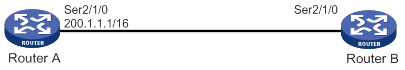
Configuration procedure
1. Configure Router A:
# Configure an IP address to be assigned to the peer interface on Serial 2/1/0.
<RouterA> system-view
[RouterA] interface serial 2/1/0
[RouterA-Serial2/1/0] remote address 200.1.1.10
# Configure an IP address for Serial 2/1/0.
[RouterA-Serial2/1/0] ip address 200.1.1.1 16
2. Enable IP address negotiation on Serial 2/1/0 of Router B.
<RouterB> system-view
[RouterB] interface serial 2/1/0
[RouterB-Serial2/1/0] ip address ppp-negotiate
3. Verify the configuration:
# Display summary information about Serial 2/1/0 on Router B.
[RouterB-Serial2/1/0] display interface serial 2/1/0 brief
Brief information on interfaces in route mode:
Link: ADM - administratively down; Stby - standby
Protocol: (s) - spoofing
Interface Link Protocol Primary IP Description
Ser2/1/0 UP UP 200.1.1.10
The output shows Serial 2/1/0 obtains IP address 200.1.1.10 through PPP negotiation.
# Verify that Router B can ping Serial 2/1/0 of Router A.
[RouterB-Serial2/1/0] ping 200.1.1.1
Ping 200.1.1.1 (200.1.1.1): 56 data bytes, press CTRL_C to break
56 bytes from 200.1.1.1: icmp_seq=0 ttl=128 time=3.197 ms
56 bytes from 200.1.1.1: icmp_seq=1 ttl=128 time=2.594 ms
56 bytes from 200.1.1.1: icmp_seq=2 ttl=128 time=2.739 ms
56 bytes from 200.1.1.1: icmp_seq=3 ttl=128 time=1.738 ms
56 bytes from 200.1.1.1: icmp_seq=4 ttl=128 time=1.744 ms
--- Ping statistics for 200.1.1.1 ---
5 packet(s) transmitted, 5 packet(s) received, 0.0% packet loss
round-trip min/avg/max/std-dev = 1.738/2.402/3.197/0.576 ms
Specifying a PPP address pool on the server interface
Network requirements
As shown in Figure 7, configure Router A to allocate an IP address from the PPP address pool on Serial 2/1/0 of Router A to Serial 2/1/0 of Router B through PPP negotiation.
Configuration procedure
1. Configure Router A:
# Configure PPP address pool aaa that contains IP addresses 200.1.1.10 through 200.1.1.20 for group AAA.
<RouterA> system-view
[RouterA] ip pool aaa 200.1.1.10 200.1.1.20 group AAA
# Configure a PPP address pool route.
[RouterA] ppp ip-pool route 200.1.1.1 24
# Configure Serial 2/1/0 to assign an IP address from aaa to the peer interface.
[RouterA] interface serial 2/1/0
[RouterA-Serial2/1/0] remote address pool aaa
# Configure an IP address for Serial 2/1/0.
[RouterA-Serial2/1/0] ip address 200.1.1.1 16
2. Enable IP address negotiation on Serial 2/1/0 of Router B.
<RouterB> system-view
[RouterB] interface serial 2/1/0
[RouterB-Serial2/1/0] ip address ppp-negotiate
3. Verify the configuration:
# Display summary information about Serial 2/1/0 on Router B.
[RouterB-Serial2/1/0] display interface serial 2/1/0 brief
Brief information on interfaces in route mode:
Link: ADM - administratively down; Stby - standby
Protocol: (s) - spoofing
Interface Link Protocol Primary IP Description
Ser2/1/0 UP UP 200.1.1.10
The output shows that Serial 2/1/0 has obtained IP address 200.1.1.10 through PPP negotiation.
# Verify that Router B can ping Serial 2/1/0 of Router A.
[RouterB-Serial2/0] ping 200.1.1.1
Ping 200.1.1.1 (200.1.1.1): 56 data bytes, press CTRL_C to break
56 bytes from 200.1.1.1: icmp_seq=0 ttl=128 time=3.197 ms
56 bytes from 200.1.1.1: icmp_seq=1 ttl=128 time=2.594 ms
56 bytes from 200.1.1.1: icmp_seq=2 ttl=128 time=2.739 ms
56 bytes from 200.1.1.1: icmp_seq=3 ttl=128 time=1.738 ms
56 bytes from 200.1.1.1: icmp_seq=4 ttl=128 time=1.744 ms
--- Ping statistics for 200.1.1.1 ---
5 packet(s) transmitted, 5 packet(s) received, 0.0% packet loss
round-trip min/avg/max/std-dev = 1.738/2.402/3.197/0.576 ms
# Display PPP address pool aaa on Serial 2/1/0 of Router A.
[RouterA-Serial2/1/0] display ip pool aaa
Group name: AAA
Pool name Start IP address End IP address Free In use
aaa 200.1.1.10 200.1.1.20 10 1
In use IP addresses:
IP address Interface
200.1.1.10 Ser2/1/0
The output shows that one IP address has been assigned.
Using the PPP address pool associated with an ISP domain
Network requirements
As shown in Figure 8, configure Router A to allocate an IP address from the PPP address pool associated with the ISP domain to Serial 2/1/0 of Router B through PPP negotiation.
Configuration procedure
1. Configure Router A:
# Configure PPP address pool aaa that contains IP addresses 200.1.1.10 through 200.1.1.20 for the group AAA.
<RouterA> system-view
[RouterA] ip pool aaa 200.1.1.10 200.1.1.20 group AAA
# Configure a PPP address pool route.
[RouterA] ppp ip-pool route 200.1.1.1 24
# Create a local user for Router B.
[RouterA] local-user userb class network
# Set a password for the local user.
[RouterA-luser-network-userb] password simple 123
# Set the service type to PPP for the local user.
[RouterA-luser-network-userb] service-type ppp
[RouterA-luser-network-userb] quit
# Create ISP domain bbb and associate aaa with bbb.
[RouterA] domain bbb
[RouterA-isp-bbb] authorization-attribute ip-pool aaa
[RouterA-isp-bbb] quit
# Configure Serial 2/1/0 to authenticate the peer interface in bbb by using PAP.
[RouterA] interface serial 2/1/0
[RouterA-Serial2/1/0] ppp authentication-mode pap domain bbb
# Configure an IP address for Serial 2/1/0.
[RouterA-Serial2/1/0] ip address 200.1.1.1 16
2. Configure Router B:
# Configure the username and password for PAP authentication by Router A.
<RouterB> system-view
[RouterB] interface serial 2/1/0
[RouterB-Serial2/1/0] ppp pap local-user userb password simple 123
# Enable IP address negotiation on Serial 2/1/0.
<RouterB> system-view
[RouterB] interface serial 2/1/0
[RouterB-Serial2/1/0] ip address ppp-negotiate
3. Verify the configuration:
# Display summary information about Serial 2/1/0 on Router B.
[RouterB-Serial2/1/0] display interface serial 2/1/0 brief
Brief information on interfaces in route mode:
Link: ADM - administratively down; Stby - standby
Protocol: (s) - spoofing
Interface Link Protocol Primary IP Description
Ser2/1/0 UP UP 200.1.1.10
The output shows that Serial 2/1/0 has obtained IP address 200.1.1.10 through PPP negotiation.
# Verify that Router B can ping Serial 2/1/0 of Router A.
[RouterB-Serial2/1/0] ping 200.1.1.1
Ping 200.1.1.1 (200.1.1.1): 56 data bytes, press CTRL_C to break
56 bytes from 200.1.1.1: icmp_seq=0 ttl=128 time=3.197 ms
56 bytes from 200.1.1.1: icmp_seq=1 ttl=128 time=2.594 ms
56 bytes from 200.1.1.1: icmp_seq=2 ttl=128 time=2.739 ms
56 bytes from 200.1.1.1: icmp_seq=3 ttl=128 time=1.738 ms
56 bytes from 200.1.1.1: icmp_seq=4 ttl=128 time=1.744 ms
--- Ping statistics for 200.1.1.1 ---
5 packet(s) transmitted, 5 packet(s) received, 0.0% packet loss
round-trip min/avg/max/std-dev = 1.738/2.402/3.197/0.576 ms
# Display the address pools on Serial 2/1/0 of Router A.
[RouterA-Serial2/1/0] display ip pool aaa
Group name: AAA
Pool name Start IP address End IP address Free In use
aaa 200.1.1.10 200.1.1.20 10 1
In use IP addresses:
IP address Interface
200.1.1.10 Ser2/1/0
The output shows that one IP address of aaa has been assigned.
MP binding mode configuration examples
Network requirements
As shown in Figure 9, to enable MP for Serial 2/1/0 and Serial 2/1/1, use one of the following methods:
· Bind the physical interfaces to a VT interface.
· Associate remote usernames with a VT interface.
· Configure an MP-group interface.
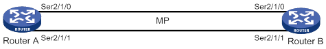
Configuration procedure
(Method 1) Binding the physical interfaces to a VT interface
1. Configure Router A:
# Create a VT interface, and configure an IP address for it.
<RouterA> system-view
[RouterA] interface virtual-template 1
[RouterA-Virtual-Template1] ip address 8.1.1.1 24
[RouterA-Virtual-Template1] quit
# Configure Serial 2/1/1.
[RouterA] interface serial 2/1/1
[RouterA-Serial2/1/1] link-protocol ppp
[RouterA-Serial2/1/1] ppp mp virtual-template 1
[RouterA-Serial2/1/1] quit
# Configure Serial 2/1/0.
[RouterA] interface serial 2/1/0
[RouterA-Serial2/1/0] link-protocol ppp
[RouterA-Serial2/1/0] ppp mp virtual-template 1
[RouterA-Serial2/1/0] quit
2. Configure Router B:
# Create a VT interface, and configure an IP address for it.
<RouterB> system-view
[RouterB] interface virtual-template 1
[RouterB-Virtual-Template1] ip address 8.1.1.2 24
[RouterB-Virtual-Template1] quit
# Configure Serial 2/1/1.
[RouterB] interface serial 2/1/1
[RouterB-Serial2/1/1] link-protocol ppp
[RouterB-Serial2/1/1] ppp mp virtual-template 1
[RouterB-Serial2/1/1] quit
# Configure Serial 2/1/0.
[RouterB] interface serial 2/1/0
[RouterB-Serial2/1/0] link-protocol ppp
[RouterB-Serial2/1/0] ppp mp virtual-template 1
[RouterB-Serial2/1/0] quit
3. Verify the configuration:
# Display MP information on Router A.
[RouterA] display ppp mp
----------------------Slot2----------------------
Template: Virtual-Template1
max-bind: 16, fragment: enabled, min-fragment: 128
Master link: Virtual-Access0, Active members: 2, Bundle H3C
Peer's endPoint descriptor: H3C
Sequence format: long (rcv)/long (sent)
Bundle Up Time: 2013/01/10 07:13:10:723
0 lost fragments, 0 reordered, 0 unassigned, 0 interleaved
Sequence: 0 (rcv)/0 (sent)
Active member channels: 2 members
Serial2/1/1 Up-Time:2013/01/10 07:13:10:724
Serial2/1/0 Up-Time:2013/01/10 07:13:11:945
# Display the status of the VA interface on Router A.
[RouterA] display interface virtual-access
Virtual-Access0
Current state: UP
Line protocol state: UP
Description: Virtual-Access0 Interface
Bandwidth: 128kbps
Maximum transmit unit: 1500
Hold timer: 10 seconds, retry times: 5
Internet address: 8.1.1.1/24 (primary)
Link layer protocol: PPP
LCP: opened, MP: opened, IPCP: opened
Physical: MP, baudrate: 128000 bps
Main interface: Virtual-Template1
Output queue - Urgent queuing: Size/Length/Discards 0/1024/0
Output queue - Protocol queuing: Size/Length/Discards 0/500/0
Output queue - FIFO queuing: Size/Length/Discards 0/75/0
Last clearing of counters: Never
Last 300 seconds input rate: 0 bytes/sec, 0 bits/sec, 0 packets/sec
Last 300 seconds output rate: 0 bytes/sec, 0 bits/sec, 0 packets/sec
Input: 2 packets, 80 bytes, 0 drops
Output: 2 packets, 24 bytes, 0 drops
4. Ping IP address 8.1.1.1 on Router B.
[RouterB] ping 8.1.1.1
Ping 8.1.1.1 (8.1.1.1): 56 data bytes, press CTRL_C to break
56 bytes from 8.1.1.1: icmp_seq=0 ttl=255 time=4.000 ms
56 bytes from 8.1.1.1: icmp_seq=1 ttl=255 time=0.000 ms
56 bytes from 8.1.1.1: icmp_seq=2 ttl=255 time=0.000 ms
56 bytes from 8.1.1.1: icmp_seq=3 ttl=255 time=0.000 ms
56 bytes from 8.1.1.1: icmp_seq=4 ttl=255 time=1.000 ms
--- Ping statistics for 8.1.1.1 ---
5 packet(s) transmitted, 5 packet(s) received, 0.0% packet loss
round-trip min/avg/max/std-dev = 0.000/1.000/4.000/1.549 ms
(Method 2) Associating remote usernames with a VT interface
5. Configure Router A:
# Configure the usernames, and passwords of remote users.
<RouterA> system-view
[RouterA] local-user usera class network
[RouterA-luser-network-usera] password simple aaa
[RouterA-luser-network-usera] service-type ppp
[RouterA-luser-network-usera] quit
[RouterA] local-user userb class network
[RouterA-luser-network-userb] password simple bbb
[RouterA-luser-network-userb] service-type ppp
[RouterA-luser-network-userb] quit
# Bind a VT interface to users.
[RouterA] ppp mp user usera bind virtual-template 1
[RouterA] ppp mp user userb bind virtual-template 1
# Create the VT interface and configure its IP address.
[RouterA] interface virtual-template 1
[RouterA-Virtual-Template1] ip address 8.1.1.1 24
[RouterA-Virtual-Template1] ppp mp binding-mode authentication
[RouterA-Virtual-Template1] quit
# Configure Serial 2/1/1.
[RouterA] interface serial 2/1/1
[RouterA-Serial2/1/1] link-protocol ppp
[RouterA-Serial2/1/1] ppp authentication-mode pap
[RouterA-Serial2/1/1] ppp pap local-user userc password simple ccc
[RouterA-Serial2/1/1] ppp mp
[RouterA-Serial2/1/1] quit
# Configure Serial 2/1/0.
[RouterA] interface serial 2/1/0
[RouterA-Serial2/1/0] link-protocol ppp
[RouterA-Serial2/1/0] ppp authentication-mode pap
[RouterA-Serial2/1/0] ppp pap local-user userd password simple ddd
[RouterA-Serial2/1/0] ppp mp
[RouterA-Serial2/1/0] quit
6. Configure Router B:
# Configure the usernames, and passwords of remote users.
<RouterB> system-view
[RouterB] local-user userc class network
[RouterB-luser-network-userc] password simple ccc
[RouterB-luser-network-userc] service-type ppp
[RouterB-luser-network-userc] quit
[RouterB] local-user userd class network
[RouterB-luser-network-userd] password simple ddd
[RouterB-luser-network-userd] service-type ppp
[RouterB-luser-network-userd] quit
# Bind a VT interface to users.
[RouterB] ppp mp user userc bind virtual-template 1
[RouterB] ppp mp user userd bind virtual-template 1
# Create the VT interface and configure its IP address.
[RouterB] interface virtual-template 1
[RouterB-Virtual-Template1] ip address 8.1.1.2 24
[RouterB-Virtual-Template1] ppp mp binding-mode authentication
[RouterB-Virtual-Template1] quit
# Configure Serial 2/1/1.
[RouterB] interface serial 2/1/1
[RouterB-Serial2/1/1] link-protocol ppp
[RouterB-Serial2/1/1] ppp authentication-mode pap
[RouterB-Serial2/1/1] ppp pap local-user usera password simple aaa
[RouterB-Serial2/1/1] ppp mp
[RouterB-Serial2/1/1] quit
# Configure Serial 2/1/0.
[RouterB] interface serial 2/1/0
[RouterB-Serial2/1/0] link-protocol ppp
[RouterB-Serial2/1/0] ppp authentication-mode pap
[RouterB-Serial2/1/0] ppp pap local-user userb password simple bbb
[RouterB-Serial2/1/0] ppp mp
[RouterB-Serial2/1/0] quit
7. Verify the configuration:
# Display the MP information on Router A.
[RouterA] display ppp mp
----------------------Slot2----------------------
Template: Virtual-Template1
max-bind: 16, fragment: enabled, min-fragment: 128
Master link: Virtual-Access0, Active members: 1, Bundle usera
Peer's endPoint descriptor: H3C
Sequence format: long (rcv)/long (sent)
Bundle Up Time: 2013/01/10 08:02:34:881
0 lost fragments, 0 reordered, 0 unassigned, 0 interleaved
Sequence: 0 (rcv)/0 (sent)
Active member channels: 1 members
Serial2/1/1 Up-Time:2013/01/10 08:02:34:881
Master link: Virtual-Access1, Active members: 1, Bundle userb
Peer's endPoint descriptor: H3C
Sequence format: long (rcv)/long (sent)
Bundle Up Time: 2013/01/10 08:06:26:633
0 lost fragments, 0 reordered, 0 unassigned, 0 interleaved
Sequence: 0 (rcv)/0 (sent)
Active member channels: 1 members
Serial2/1/0 Up-Time:2013/01/10 08:06:26:634
# Display the MP information on Router B.
[RouterB] display ppp mp
Template: Virtual-Template1
max-bind: 16, fragment: enabled, min-fragment: 128
Master link: Virtual-Access2, Active members: 1, Bundle userc
Peer's endPoint descriptor: H3C
Sequence format: long (rcv)/long (sent)
Bundle Up Time: 2013/01/10 12:31:13:391
0 lost fragments, 0 reordered, 0 unassigned, 0 interleaved
Sequence: 0 (rcv)/0 (sent)
Active member channels: 1 members
Serial2/1/1 Up-Time:2013/01/10 12:31:13:392
Master link: Virtual-Access3, Active members: 1, Bundle userd
Peer's endPoint descriptor: H3C
Sequence format: long (rcv)/long (sent)
Bundle Up Time: 2013/01/10 12:35:05:88
0 lost fragments, 0 reordered, 0 unassigned, 0 interleaved
Sequence: 0 (rcv)/0 (sent)
Active member channels: 1 members
Serial2/1/0 Up-Time:2013/01/10 12:35:05:89
# Display the status of the VA interfaces on Router B.
[RouterB] display interface virtual-access
Virtual-Access2
Current state: UP
Line protocol state: UP
Description: Virtual-Access2 Interface
Bandwidth: 64kbps
Maximum transmit unit: 1500
Hold timer: 10 seconds, retry times: 5
Internet address: 8.1.1.2/24 (primary)
Link layer protocol: PPP
LCP: opened, MP: opened, IPCP: opened
Physical: MP, baudrate: 64000 bps
Main interface: Virtual-Template1
Output queue - Urgent queuing: Size/Length/Discards 0/1024/0
Output queue - Protocol queuing: Size/Length/Discards 0/500/0
Output queue - FIFO queuing: Size/Length/Discards 0/75/0
Last clearing of counters: Never
Last 300 seconds input rate: 0 bytes/sec, 0 bits/sec, 0 packets/sec
Last 300 seconds output rate: 0 bytes/sec, 0 bits/sec, 0 packets/sec
Input: 2 packets, 80 bytes, 0 drops
Output: 2 packets, 24 bytes, 0 drops
Virtual-Access3
Current state: UP
Line protocol state: UP
Description: Virtual-Access3 Interface
Bandwidth: 64kbps
Maximum transmit unit: 1500
Hold timer: 10 seconds, retry times: 5
Internet address: 8.1.1.2/24 (primary)
Link layer protocol: PPP
LCP: opened, MP: opened, IPCP: opened
Physical: MP, baudrate: 64000 bps
Main interface: Virtual-Template1
Output queue - Urgent queuing: Size/Length/Discards 0/100/0
Output queue - Protocol queuing: Size/Length/Discards 0/500/0
Output queue - FIFO queuing: Size/Length/Discards 0/75/0
Last clearing of counters: Never
Last 300 seconds input rate: 0 bytes/sec, 0 bits/sec, 0 packets/sec
Last 300 seconds output rate: 0 bytes/sec, 0 bits/sec, 0 packets/sec
Input: 2 packets, 80 bytes, 0 drops
Output: 2 packets, 24 bytes, 0 drops
# Ping IP address 8.1.1.1 on Router B.
[RouterB] ping 8.1.1.1
Ping 8.1.1.1 (8.1.1.1): 56 data bytes, press CTRL_C to break
56 bytes from 8.1.1.1: icmp_seq=0 ttl=255 time=0.000 ms
56 bytes from 8.1.1.1: icmp_seq=1 ttl=255 time=0.000 ms
56 bytes from 8.1.1.1: icmp_seq=2 ttl=255 time=1.000 ms
56 bytes from 8.1.1.1: icmp_seq=3 ttl=255 time=1.000 ms
56 bytes from 8.1.1.1: icmp_seq=4 ttl=255 time=0.000 ms
--- Ping statistics for 8.1.1.1 ---
5 packet(s) transmitted, 5 packet(s) received, 0.0% packet loss
round-trip min/avg/max/std-dev = 0.000/0.400/1.000/0.490 ms
(Method 3) Configuring an MP-group interface
8. Configure Router A:
# Create an MP-group interface, and configure an IP address for it.
<RouterA> system-view
[RouterA] interface mp-group 2/0/0
[RouterA-MP-group2/0/0] ip address 1.1.1.1 24
# Configure interface Serial 2/1/1.
[RouterA-MP-group2/0/0] quit
[RouterA] interface serial 2/1/1
[RouterA-Serial2/1/1] link-protocol ppp
[RouterA-Serial2/1/1] ppp mp mp-group 2/0/0
[RouterA-Serial2/1/1] shutdown
[RouterA-Serial2/1/1] undo shutdown
[RouterA-Serial2/1/1] quit
# Configure interface Serial 2/1/0.
[RouterA] interface serial 2/1/0
[RouterA-Serial2/1/0] link-protocol ppp
[RouterA-Serial2/1/0] ppp mp mp-group 2/0/0
[RouterA-Serial2/1/0] shutdown
[RouterA-Serial2/1/0] undo shutdown
[RouterA-Serial2/1/0] quit
9. Configure Router B:
# Create an MP-group interface, and configure an IP address for it.
[RouterB] interface mp-group 2/0/0
[RouterB-Mp-group2/0/0] ip address 1.1.1.2 24
[RouterB-Mp-group2/0/0] quit
# Configure interface Serial 2/1/1.
[RouterB] interface serial 2/1/1
[RouterB-Serial2/1/1] link-protocol ppp
[RouterB-Serial2/1/1] ppp mp mp-group 2/0/0
[RouterB-Serial2/1/1] shutdown
[RouterB-Serial2/1/1] undo shutdown
[RouterB-Serial2/1/1] quit
# Configure interface Serial 2/1/0.
[RouterB] interface serial 2/1/0
[RouterB-Serial2/1/0] link-protocol ppp
[RouterB-Serial2/1/0] ppp mp mp-group 2/0/0
[RouterB-Serial2/1/0] shutdown
[RouterB-Serial2/1/0] undo shutdown
[RouterB-Serial2/1/0] quit
10. Verify the configuration:
# Display MP information on Router A.
[RouterA] display ppp mp
----------------------Slot2----------------------
Template: MP-group2/0/0
max-bind: 16, fragment: enabled, min-fragment: 128
Master link: MP-group2/0/0, Active members: 2, Bundle Multilink
Peer's endPoint descriptor: MP-group2/0/0
Sequence format: long (rcv)/long (sent)
Bundle Up Time: 2012/11/04 09:03:16:612
0 lost fragments, 0 reordered, 0 unassigned, 0 interleaved
Sequence: 0 (rcvd)/0 (sent)
Active member channels: 2 members
Serial2/1/0 Up-Time:2012/11/04 09:03:16:613
Serial2/1/1 Up-Time:2012/11/04 09:03:42:945
# Display information about interface MP-group2/0/0 on Router A.
[RouterA] display interface mp-group 2/0/0
MP-group2/0/0
Current state: UP
Line protocol state: UP
Description: MP-group2/0/0 Interface
Bandwidth: 2048kbps
Maximum transmit unit: 1500
Hold timer: 10 seconds, retry times: 5
Internet address: 1.1.1.1/24 (primary)
Link layer protocol: PPP
LCP: opened, MP: opened, IPCP: opened
Physical: MP, baudrate: 2048000 bps
Output queue - Urgent queuing: Size/Length/Discards 0/100/0
Output queue - Protocol queuing: Size/Length/Discards 0/500/0
Output queue - FIFO queuing: Size/Length/Discards 0/75/0
Last clearing of counters: Never
Last 300 seconds input rate: 0 bytes/sec, 0 bits/sec, 0 packets/sec
Last 300 seconds output rate: 0 bytes/sec, 0 bits/sec, 0 packets/sec
Input: 2 packets, 80 bytes, 0 drops
Output: 2 packets, 24 bytes, 0 drops
# Ping Router B from Router A.
[RouterA] ping 1.1.1.2
Ping 1.1.1.2 (1.1.1.2): 56 data bytes, press CTRL_C to break
56 bytes from 1.1.1.2: icmp_seq=0 ttl=255 time=4.000 ms
56 bytes from 1.1.1.2: icmp_seq=1 ttl=255 time=1.000 ms
56 bytes from 1.1.1.2: icmp_seq=2 ttl=255 time=0.000 ms
56 bytes from 1.1.1.2: icmp_seq=3 ttl=255 time=7.000 ms
56 bytes from 1.1.1.2: icmp_seq=4 ttl=255 time=1.000 ms
--- Ping statistics for 1.1.1.2 ---
5 packet(s) transmitted, 5 packet(s) received, 0.0% packet loss
round-trip min/avg/max/std-dev = 0.000/2.600/7.000/2.577 ms
Configuring PPPoE
Overview
Point-to-Point Protocol over Ethernet (PPPoE) extends PPP by transporting PPP frames encapsulated in Ethernet over point-to-point links.
PPPoE specifies the methods for establishing PPPoE sessions and encapsulating PPP frames over Ethernet. PPPoE requires a point-to-point relationship between peers instead of a point-to-multipoint relationship as in multi-access environments such as Ethernet. PPPoE provides Internet access for the hosts in an Ethernet through a remote access device and implement access control, authentication, and accounting on a per-host basis. Integrating the low cost of Ethernet and scalability and management functions of PPP, PPPoE gained popularity in various application environments, such as residential access networks.
For more information about PPPoE, see RFC 2516.
Compatibility information
Feature and hardware compatibility
|
Hardware |
PPPoE compatibility |
|
MSR810/810-W/810-W-DB/810-LM/810-W-LM/810-10-PoE/810-LM-HK/810-W-LM-HK |
Yes |
|
MSR810-LMS/810-LUS |
Yes only for PPPoE client |
|
MSR2600-6-X1/2600-10-X1 |
Yes |
|
MSR 2630 |
Yes |
|
MSR3600-28/3600-51 |
Yes |
|
MSR3600-28-SI/3600-51-SI |
No |
|
MSR3610-X1/3610-X1-DP/3610-X1-DC/3610-X1-DP-DC |
Yes |
|
MSR 3610/3620/3620-DP/3640/3660 |
Yes |
|
MSR5620/5660/5680 |
Yes |
|
Hardware |
PPPoE compatibility |
|
MSR810-LM-GL |
Yes |
|
MSR810-W-LM-GL |
Yes |
|
MSR830-6EI-GL |
Yes |
|
MSR830-10EI-GL |
Yes |
|
MSR830-6HI-GL |
Yes |
|
MSR830-10HI-GL |
Yes |
|
MSR2600-6-X1-GL |
Yes |
|
MSR3600-28-SI-GL |
No |
The device does not support this feature in IRF mode.
Command and hardware compatibility
IPv6-related parameters are not supported on the following routers:
· MSR810/810-W/810-W-DB/810-LM/810-W-LM/810-10-PoE/810-LM-HK/810-W-LM-HK/810-LMS/810-LUS.
· MSR3600-28-SI/3600-51-SI.
· MSR810-LM-GL/810-W-LM-GL/830-6EI-GL/830-10EI-GL/830-6HI-GL/830-10HI-GL/2600-6-X1-GL/3600-28-SI-GL.
PPPoE network structure
PPPoE uses the client/server model. The PPPoE client initiates a connection request to the PPPoE server. After session negotiation between them is complete, a session is established between them, and the PPPoE server provides access control, authentication, and accounting to the PPPoE client.
Depending on the starting point of the PPPoE session, the following network structures are available:
· As shown in Figure 10, the PPPoE session is established between routers (Router A and Router B). All hosts share one PPPoE session for data transmission without being installed with PPPoE client software. This network structure is typically used by enterprises.
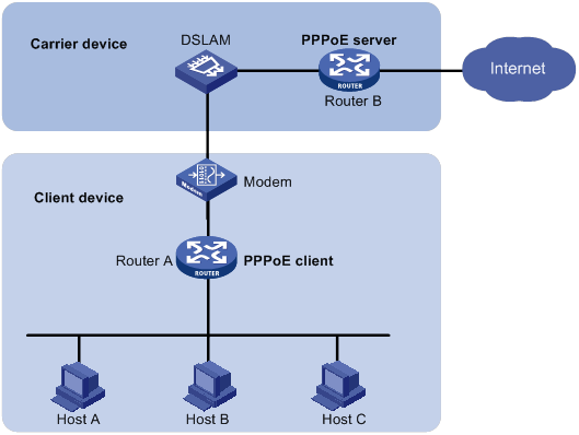
· As shown in Figure 11, a PPPoE session is established between each host (PPPoE client) and the carrier router (PPPoE server). The service provider assigns an account to each host for billing and control. The host must be installed with PPPoE client software.
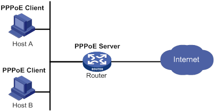
Configuring the PPPoE server
Configuring a PPPoE session
|
Step |
Command |
Remarks |
|
1. Enter system view. |
system-view |
N/A |
|
2. Create a VT interface and enter VT interface view. |
interface virtual-template number |
N/A |
|
3. Set PPP parameters. |
See "Configuring PPP." |
If authentication is needed, use the PPPoE server as the authenticator. |
|
4. Enable MRU verification. |
ppp lcp echo mru verify [ minimum value ] |
By default, MRU verification is disabled. |
|
5. Return to system view. |
quit |
N/A |
|
6. Enter Layer 3 Ethernet interface/subinterface, Layer 3 virtual Ethernet interface/subinterface, VLAN interface, Layer 3 aggregate interface/subinterface, L3VE interface/subinterface, or EFM interface/subinterface view. |
interface interface-type interface-number |
N/A |
|
7. Enable the PPPoE server on the interface and bind this interface to the specified VT interface. |
pppoe-server bind virtual-template number |
By default, the PPPoE server is disabled on the interface. |
|
8. (Optional.) Configure an access controller (AC) name for the PPPoE server. |
pppoe-server tag ac-name name |
By default, the AC name for the PPPoE server is the device name. PPPoE clients can choose a PPPoE server according to the AC name. The PPPoE client on H3C devices do not support this feature. |
|
9. (Optional.) Enable the PPPoE server to support the ppp-max-payload tag and specify a range for the PPP maximum payload. |
pppoe-server tag ppp-max-payload [ minimum minvalue maximum maxvalue ] |
By default, The PPPoE server does not support the ppp-max-payload tag. |
|
10. (Optional.) Set a service name for the PPPoE server |
pppoe-server tag service-name name |
By default, the PPPoE server does not have a service name. |
|
11. (Optional) Set the response delay time for user access. |
pppoe-server access-delay delay-time |
By default, no response delay time is set. |
|
12. Return to system view. |
quit |
N/A |
|
13. Configure the PPPoE server to perform authentication, authorization, and accounting for PPP users. |
See Security Configuration Guide. |
N/A |
Setting the maximum number of PPPoE sessions
PPPoE can establish a session when none of the following limits are reached:
· Limit for a user on an interface.
· Limit for a VLAN on an interface.
· Limit on an interface.
· Limit on a card. (Distributed devices in standalone.)
· Limit on a device. (Centralized devices in standalone mode.)
New maximum number settings apply only to subsequently established PPPoE sessions.
The maximum number of PPPoE sessions supported by a device varies by license or device model.
The maximum number of PPPoE sessions set for a device cannot be greater than the maximum number of PPPoE sessions supported by the device. (Centralized devices in standalone mode.)
To configure the maximum number of PPPoE sessions:
|
Step |
Command |
Remarks |
|
1. Enter system view. |
system-view |
N/A |
|
2. Enter Layer 3 Ethernet interface/subinterface, Layer 3 virtual Ethernet interface/subinterface, VLAN interface, Layer 3 aggregate interface/subinterface, L3VE interface/subinterface, or EFM interface/subinterface view. |
interface interface-type interface-number |
The PPPoE server is enabled on the interface. |
|
3. Set the maximum number of PPPoE sessions on an interface. |
pppoe-server session-limit number |
By default, the number of PPPoE sessions on an interface is not limited. |
|
4. Set the maximum number of PPPoE sessions for a VLAN on an interface. |
pppoe-server session-limit per-vlan number |
By default, the number of PPPoE sessions for a VLAN on an interface is not limited. |
|
5. Set the maximum number of PPPoE sessions for a user on an interface. |
pppoe-server session-limit per-mac number |
By default, a user is allowed to create a maximum of 100 PPPoE sessions. |
|
6. Return to system view. |
quit |
N/A |
|
7. Set the maximum number of PPPoE sessions on a device (centralized devices in standalone mode). |
pppoe-server session-limit total number |
By default, the number of PPPoE sessions on a device is not limited. |
|
8. Set the maximum number of PPPoE sessions on the specified card (distributed devices in standalone mode). |
pppoe-server session-limit slot slot-number total number |
By default, the number of PPPoE sessions on a card is not limited. |
Limiting the PPPoE access rate
The device can limit the rate at which a user (identified by an MAC address) can create PPPoE sessions on an interface. If the number of PPPoE requests within the monitoring time exceeds the configured threshold, the device discards the excessive requests, and outputs log messages. If the blocking time is set to 0, the device does not block any requests, and it only outputs log messages.
The device uses a monitoring table and a blocking table to control PPP access rates:
· Monitoring table—Stores a maximum of 8000 monitoring entries. Each entry records the number of PPPoE sessions created by a user within the monitoring time. When the monitoring entries reach the maximum, the system stops monitoring and blocking session requests from new users. The aging time of monitoring entries is determined by the session-request-period argument. When the timer expires, the system starts a new round of monitoring for the user.
· Blocking table—Stores a maximum of 8000 blocking entries. The system creates a blocking entry if the access rate of a user reaches the threshold, and blocks requests from that user. When the blocking entries reach the maximum number, the system stops blocking session requests from new users and it only outputs log messages. The aging time of the blocking entries is determined by the blocking-period argument. When the timer expires, the system starts a new round of monitoring for the user.
If the access rate setting is changed, the system removes all monitoring and blocking entries, and uses the new settings to limit PPPoE access rates.
To limit the PPPoE access rate:
|
Step |
Command |
Remarks |
|
1. Enter system view. |
system-view |
N/A |
|
2. Enter Layer 3 Ethernet interface/subinterface, Layer 3 virtual Ethernet interface/subinterface, VLAN interface, Layer 3 aggregate interface/subinterface, L3VE interface/subinterface, or EFM interface/subinterface view. |
interface interface-type interface-number |
The PPPoE server is enabled on the interface. |
|
3. Set the PPPoE access limit. |
pppoe-server throttle per-mac session-requests session-request-period blocking-period |
By default, the PPPoE access rate is not limited. |
|
4. Display information about blocked users (centralized devices in standalone mode). |
display pppoe-server throttled-mac [ interface interface-type interface-number ] |
Available in any view. |
|
5. Display information about blocked users (distributed devices in standalone mode). |
display pppoe-server throttled-mac { slot slot-number | interface interface-type interface-number } |
Available in any view. |
Configuring the NAS-Port-ID attribute
The PPPoE server on a BAS device uses the RADIUS NAS-Port-ID attribute to send the access line ID received from a DSLAM device to the RADIUS server. The access line ID includes the circuit-id and remote-id. The RADIUS server compares the received NAS-Port-ID attribute with the local line ID information to verify the location of the user.
You can configure the content of the NAS-Port-ID attribute that the PPPoE server sends to the RADIUS server.
To configure the NAS-Port-ID attribute:
|
Step |
Command |
Remarks |
|
1. Enter system view. |
system-view |
N/A |
|
2. Enter Layer 3 Ethernet interface/subinterface, Layer 3 virtual Ethernet interface/subinterface, VLAN interface, Layer 3 aggregate interface/subinterface, L3VE interface/subinterface, or EFM interface/subinterface view. |
interface interface-type interface-number |
The PPPoE server is enabled on the interface. |
|
3. Configure the content of the NAS-Port-ID attribute. |
pppoe-server access-line-id content { all [ separator ] | circuit-id | remote-id } |
By default, the NAS-Port-ID attribute contains only the circuit-id. |
|
4. Configure the NAS-Port-ID attribute to include the BAS information automatically. |
pppoe-server access-line-id bas-info [ cn-163 ] |
By default, the NAS-Port-ID attribute does not include the BAS information automatically. |
|
5. Configure the PPPoE server to trust the access line ID in received packets. |
pppoe-server access-line-id trust |
By default, the PPPoE server does not trust the access line ID in received packets. |
|
6. Configure the format that is used to parse the circuit-id. |
pppoe-server access-line-id circuit-id parse-mode { cn-telecom | tr-101 } |
The default mode is TR-101. |
|
7. Configure the transmission format for the circuit-id. |
pppoe-server access-line-id circuit-id trans-format { ascii | hex } |
The default format is a string of characters. |
|
8. Configure the transmission format for the remote-id. |
pppoe-server access-line-id remote-id trans-format { ascii | hex } |
The default format is a string of characters. |
Configuring a VA pool
The PPPoE server creates a VA interface for a PPPoE session to transmit packets between PPPoE and PPP, and removes the VA interface when the user goes offline. Creating and removing VA interfaces take time.
You can configure VA pools to improve the performance of PPPoE session establishment and termination. A VA pool contains a group of automatically numbered VA interfaces. The PPPoE server selects a VA interface from the pool for a requesting user and places the interface back to the VA pool when the user goes offline. When the VA pool is exhausted, the system creates VA interfaces for new PPPoE sessions, and removes those VA interfaces when the users go offline.
On a VT interface, you can create one global VA pool and one regional VA pool per member device for interfaces bound with the VT interface.
· The global VA pool contains VA interfaces for logical interfaces that might span multiple devices, such as Ethernet aggregate interfaces.
· The regional VA pool contains VA interfaces for interfaces that do not span multiple devices, such as Ethernet interfaces.
When you configure a VA pool, follow these guidelines:
· To change the capacity of a VA pool, you must delete the previous configuration, and reconfigure the VA pool.
· Creating or removing a VA pool takes time. During the process of creating or removing a VA pool, users can come online or go offline, but the VA pool does not take effect.
· If the system fails to create a VA pool because of insufficient resources, you can view the available resources by using the display pppoe-server va-pool command.
· VA pools are memory intensive. Set their capacity depending on your network requirements.
· Deleting a VA pool does not log off the users who are using VA interfaces in the VA pool.
To configure a VA pool:
|
Step |
Command |
Remarks |
|
1. Enter system view. |
system-view |
N/A |
|
2. Create a VA pool (centralized devices in standalone mode). |
pppoe-server virtual-template template-number va-pool va-volume |
By default, no VA pool exists. |
|
3. Create a VA pool (distributed devices in standalone mode). |
pppoe-server virtual-template template-number [ slot slot-number ] va-pool va-volume |
By default, no VA pool exists. |
Clearing PPPoE sessions
To clear PPPoE sessions on the PPPoE server:
|
Step |
Command |
Remarks |
|
1. Enter user view. |
user-view |
N/A |
|
2. Clear PPPoE sessions. |
reset pppoe-server { all | interface interface-type interface-number | virtual-template number } |
N/A |
Configuring a PPPoE client
PPPoE client configuration includes dialer interface configuration and PPPoE session configuration.
A PPPoE session can operate in one of the following modes:
· Permanent mode—A PPPoE session is established immediately when the line is physically up. This type of session remains until the physical link comes down or until the session is disconnected.
· On-demand mode—A PPPoE session is established when there is a demand for data transmission instead of when the line is physically up. It is terminated when idled for a specific period of time.
· Diagnostic mode—A PPPoE session is established immediately after the device configurations finish. The device automatically terminates the PPPoE session and then tries to re-establish a PPPoE session at a pre-configured interval. By establishing and terminating PPPoE sessions periodically, you can monitor the operating status of the PPPoE link.
The PPPoE session operating mode is determined by your configuration on the dialer interface:
· Permanent mode—Used when you set the link idle time to 0 by using the dialer timer idle command and do not configure the dialer diagnose command.
· On-demand mode—Used when you set the link idle time to a non-zero value by using the dialer timer idle command and do not configure the dialer diagnose command.
· Diagnostic mode—Used when you configure the dialer diagnose command.
Configuring a dialer interface
Before establishing a PPPoE session, you must first create a dialer interface and configure bundle DDR on the interface. Each PPPoE session uniquely corresponds to a dialer bundle, and each dialer bundle uniquely corresponds to a dialer interface. A PPPoE session uniquely corresponds to a dialer interface.
For more information about configuring dialer interfaces, bundle DDR, and dialer bundles, see "Configuring DDR."
Configuring a dialer interface for a PPPoE client
|
Step |
Command |
Remarks |
|
1. Enter system view. |
system-view |
N/A |
|
2. Create a dialer access group and configure a dial access control rule. |
dialer-group group-number rule { ip | ipv6 } { deny | permit | acl { acl-number | name acl-name } } |
By default, no dialer group exists. |
|
3. Create a dialer interface and enter its view. |
interface dialer number |
N/A |
|
4. Assign an IP address to the interface. |
ip address { address mask | ppp-negotiate } |
By default, no IP address is configured. |
|
5. Enable bundle DDR on the interface. |
dialer bundle enable |
By default, no DDR is enabled. |
|
6. Associate the interface with the dial access control rule by associating the interface with the corresponding dialer access group. |
dialer-group group-number |
By default, a dialer interface is not assigned to any dialer group. |
|
7. Configure the link-idle timeout timer. |
dialer timer idle idle [ in | in-out ] |
The default setting is 120 seconds. When this timer is set to 0 seconds, the PPPoE session operates in permanent mode. Otherwise, the PPPoE session operates in on-demand mode. |
|
8. Configure the DDR application to operate in diagnostic mode. |
dialer diagnose [ interval interval ] |
By default, the DDR application operates in non-diagnostic mode. When DDR operates in diagnostic mode, the link-idle timeout timer is ignored. |
|
9. Set the auto-dial interval. |
dialer timer autodial autodial-interval |
The default setting is 300 seconds. In permanent or diagnostic mode, DDR starts the auto-dial timer after the link is disconnected and originates a new call when the auto-dial timer expires. As a best practice, set a shorter auto-dial interval for DDR to soon originate a new call. |
|
10. Set the MTU for the dialer interface |
mtu size |
By default, the MTU on a dialer interface is 1500 bytes. The dialer interface fragments a packet that exceeds the configured MTU, and adds a 2-byte PPP header and a 6-byte PPPoE header to each fragment. You should modify the MTU of a dialer interface to make sure the total length of any fragment packet is less than the MTU of the physical interface. |
Configuring a PPPoE session
|
Step |
Command |
Remarks |
|
1. Enter system view. |
system-view |
N/A |
|
2. Enter Layer 3 Ethernet interface/subinterface, Layer 3 virtual Ethernet interface/subinterface, VLAN interface view, or Layer 3 aggregate interface/subinterface view. |
interface interface-type interface-number |
N/A |
|
3. Create a PPPoE session and specify a dialer bundle for the session. |
pppoe-client dial-bundle-number number [ no-hostuniq ] |
By default, no PPPoE sessions are created. The number argument in this command must take the same value as the configured dialer interface number. |
Resetting a PPPoE session
After you reset a PPPoE session in permanent mode, the device establishes a new PPPoE session when the autodial timer expires.
After you reset a PPPoE session in on-demand mode, the device establishes a new PPPoE session when there is a demand for data transmission.
To reset a PPPoE session:
|
Step |
Command |
Remarks |
|
1. Reset a PPPoE session. |
reset pppoe-client { all | dial-bundle-number number } |
Available in user view. |
Displaying and maintaining PPPoE
Displaying and maintaining PPPoE server
Execute display commands in any view.
|
Task |
Command |
|
Display summary information for PPPoE sessions (centralized devices in standalone mode). |
display pppoe-server session summary [ interface interface-type interface-number ] |
|
Display summary information for PPPoE sessions (distributed devices in standalone mode). |
display pppoe-server session summary { slot slot-number | interface interface-type interface-number } |
|
Display packet statistics for PPPoE sessions (centralized devices in standalone mode). |
display pppoe-server session packet [ interface interface-type interface-number ] |
|
Display packet statistics for PPPoE sessions (distributed devices in standalone mode). |
display pppoe-server session packet { slot slot-number | interface interface-type interface-number } |
|
Display information about blocked users (centralized devices in standalone mode). |
display pppoe-server throttled-mac [ interface interface-type interface-number ] |
|
Display VA pool information. |
display pppoe-server va-pool |
Displaying and maintaining PPPoE client
Execute display commands in any view and reset commands in user view.
|
Task |
Command |
|
Display summary information for a PPPoE session. |
display pppoe-client session summary [ dial-bundle-number number ] |
|
Display the protocol packet statistics for a PPPoE session. |
display pppoe-client session packet [ dial-bundle-number number ] |
|
Clear the protocol packet statistics for a PPPoE session. |
reset pppoe-client session packet [ dial-bundle-number number ] |
PPPoE configuration examples
PPPoE server configuration example
Network requirements
As shown in Figure 12, Host A and Host B run PPPoE client dialup software. The PPPoE server on the router performs local authentication and assigns IP addresses to the clients.
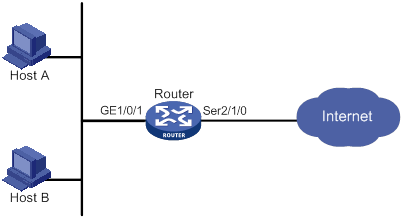
Configuration procedure
# Create a PPPoE user.
<Router> system-view
[Router] local-user user1 class network
[Router-luser-network-user1] password simple pass1
[Router-luser-network-user1] service-type ppp
[Router-luser-network-user1] quit
# Configure Virtual-Template 1 to use CHAP for authentication and use a PPP address pool for IP address assignment.
[Router] interface virtual-template 1
[Router-Virtual-Template1] ppp authentication-mode chap domain system
[Router-Virtual-Template1] ppp chap user user1
[Router-Virtual-Template1] remote address pool 1
[Router-Virtual-Template1] ip address 1.1.1.1 255.0.0.0
[Router-Virtual-Template1] quit
# Configure a PPP address pool that contains nine assignable IP addresses.
[Router] ip pool 1 1.1.1.2 1.1.1.10
# Enable the PPPoE server on GigabitEthernet 1/0/1, and bind the interface to Virtual-Template 1.
[Router] interface gigabitethernet 1/0/1
[Router-GigabitEthernet1/0/1] pppoe-server bind virtual-template 1
[Router-GigabitEthernet1/0/1] quit
# Configure local authentication for the default ISP domain (system).
[Router] domain system
[Router-isp-system] authentication ppp local
[Router-isp-system] quit
Verifying the configuration
# Verify that Host A and Host B can access the Internet by using username user1 and password pass1. (Details not shown.)
PPPoE server IP address assignment through the local DHCP server configuration example
Network requirements
As shown in Figure 13, configure the PPPoE server as a DHCP server to assign an IP address to the host.
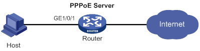
Configuration procedure
# Configure Virtual-Template 10 to use PAP for authentication and use a DHCP address pool for IP address assignment.
<Router> system-view
[Router] interface virtual-template 10
[Router-Virtual-Template10] ppp authentication-mode pap
[Router-Virtual-Template10] remote address pool pool1
[Router-Virtual-Template10] quit
# Enable the PPPoE server on GigabitEthernet 1/0/1, and bind the interface to Virtual-Template 10.
[Router] interface gigabitethernet 1/0/1
[Router-GigabitEthernet1/0/1] pppoe-server bind virtual-template 10
[Router-GigabitEthernet1/0/1] quit
# Enable DHCP.
[Router] dhcp enable
# Configure DHCP address pool pool1.
[Router] dhcp server ip-pool pool1
[Router-dhcp-pool-pool1] network 1.1.1.0 24
[Router-dhcp-pool-pool1] gateway-list 1.1.1.1 export-route
[Router-dhcp-pool-pool1] quit
# Create a PPPoE user.
[Router] local-user user1 class network
[Router-luser-network-user1] password simple pass1
[Router-luser-network-user1] service-type ppp
[Router-luser-network-user1] quit
Verifying the configuration
# Log in to the router by using username user1 and password pass1.
# Display information about IP addresses assigned by the DHCP server.
[Router] display dhcp server ip-in-use
IP address Client identifier/ Lease expiration Type
Hardware address
1.1.1.2 3030-3030-2e30-3030- Unlimited Auto(C)
662e-3030-3033-2d45-
7468-6572-6e65-74
The output shows that the router has assigned an IP address to the host.
PPPoE server IP address assignment through a remote DHCP server configuration example
Network requirements
As shown in Figure 14, configure the PPPoE server as a DHCP relay agent to relay an IP address from the DHCP server to the host.
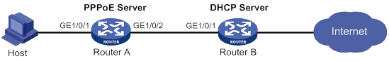
Configuration procedure
1. Configure Router A as the PPPoE server:
# Configure Virtual-Template 10 to use PAP for authentication and use a DHCP address pool for IP address assignment.
<RouterA> system-view
[RouterA] interface virtual-template 10
[RouterA-Virtual-Template10] ppp authentication-mode pap
[RouterA-Virtual-Template10] remote address pool pool1
[RouterA-Virtual-Template10] quit
# Enable the PPPoE server on GigabitEthernet 1/0/1, and bind the interface to Virtual-Template 10.
[RouterA] interface gigabitethernet 1/0/1
[RouterA-GigabitEthernet1/0/1] pppoe-server bind virtual-template 10
[RouterA-GigabitEthernet1/0/1] quit
# Enable DHCP.
[RouterA] dhcp enable
# Enable recording of relay entries on the relay agent.
[RouterA] dhcp relay client-information record
# Create DHCP relay address pool pool1.
[RouterA] dhcp server ip-pool pool1
# Specify a gateway address for the clients in pool1.
[RouterA-dhcp-pool-pool1] gateway-list 2.2.2.1 export-route
# Specify a DHCP server for pool1.
[RouterA-dhcp-pool-pool1] remote-server 10.1.1.1
[RouterA-dhcp-pool-pool1] quit
# Specify an IP address for GigabitEthernet 1/0/2.
[RouterA] interface gigabitethernet 1/0/2
[RouterA-GigabitEthernet1/0/2] ip address 10.1.1.2 24
[RouterA-GigabitEthernet1/0/2] quit
# Create a PPPoE user.
[RouterA] local-user user1 class network
[RouterA-luser-network-user1] password simple pass1
[RouterA-luser-network-user1] service-type ppp
[RouterA-luser-network-user1] quit
2. Configure Router B as a DHCP server:
# Enable DHCP.
<RouterB> system-view
[RouterB] dhcp enable
# Create DHCP address pool pool1, and specify a primary subnet and a gateway address for DHCP clients.
[RouterB] dhcp server ip-pool pool1
[RouterB-dhcp-pool-pool1] network 2.2.2.0 24
[RouterB-dhcp-pool-pool1] gateway-list 2.2.2.1
[RouterB-dhcp-pool-pool1] quit
# Specify an IP address for GigabitEthernet 1/0/1.
[RouterB] interface gigabitethernet 1/0/1
[RouterB-GigabitEthernet1/0/1] ip address 10.1.1.1 24
[RouterB-GigabitEthernet1/0/1] quit
# Configure a static route to the PPPoE server.
[RouterB] ip route-static 2.2.2.0 24 10.1.1.2
Verifying the configuration
# Log in to Router A by using username user1 and password pass1.
# Display relay entries on the DHCP relay agent on Router A.
[RouterA] display dhcp relay client-information
Total number of client-information items: 1
Total number of dynamic items: 1
Total number of temporary items: 0
IP address MAC address Type Interface VPN name
2.2.2.3 00e0-0000-0001 Dynamic VA1 N/A
# Display information about the assigned IP addresses on Router B.
[RouterB] display dhcp server ip-in-use
IP address Client identifier/ Lease expiration Type
Hardware address
2.2.2.3 0030-3065-302e-3030- Dec 30 11:28:18 2016 Auto(C)
3030-2e30-3030-312d-
6666-6666-6666-6666
The output shows that Router B has assigned an IP address to the host.
PPPoE server RADIUS-based IP address assignment configuration example
Network requirements
As shown in Figure 15, configure the PPPoE server to meet the following requirements:
· The PPPoE server uses the RADIUS server to perform authentication, authorization, and accounting for access users
· The RADIUS server assigns access users a PPP address pool named pool1 and a VPN instance named vpn1.
· Users in vpn1 obtain IP addresses from PPP address pool pool1.
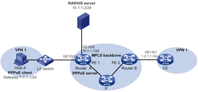
Configuration procedure
1. Configure the MPLS L3VPN feature.
For the two ends of VPN 1 to communicate with each other, specify the same route target attributes on the two PEs (Router A and Router B). This example describes only the authentication-related configuration on the PE that is connected to the PPPoE client. For information about configuring MPLS L3VPN, see MPLS Configuration Guide.
2. Configure the RADIUS server:
This example uses Free RADIUS that runs in the Linux operating system.
# Add the following text to the client.conf file to configure RADIUS client information.
client 10.1.1.1/24 {
secret = radius
shortname = sr88
}
Where, secret represents the shared key for authentication, authorization, and accounting.
# Add the following text to the users.conf file to configure legal user information.
user1 Auth-Type == CHAP,User-Password := pass1
Service-Type = Framed-User,
Framed-Protocol = PPP,
Framed-IPv6-Pool = "pool1",
H3C-VPN-Instance = "vpn1",
3. Configure Router A:
a. Configure the PPPoE server:
# Configure Virtual-Template 1 to use CHAP for authentication and use ISP domain dm1 as the authentication domain.
<RouterA> system-view
[RouterA] interface virtual-template 1
[RouterA-Virtual-Template1] ppp authentication-mode chap domain dm1
[RouterA-Virtual-Template1] quit
# Create VPN instance vpn1.
[RouterA] ip vpn-instance vpn1
# Create a PPP address pool that contains nine assignable IP addresses.
[RouterA] ip pool pool1 1.1.1.2 1.1.1.10 group 1
# Specify gateway address 1.1.1.1 and VPN instance vpn1 for pool1.
[RouterA] ip pool pool1 gateway 1.1.1.1 vpn-instance vpn1
# Configure a PPP address pool route for pool1.
[RouterA] ppp ip-pool route 1.1.1.1 24 vpn-instance vpn1
# Enable the PPPoE server on GigabitEthernet 1/0/1, and bind the interface to Virtual-Template 1.
[RouterA] interface gigabitethernet 1/0/1
[RouterA-GigabitEthernet1/0/1] pppoe-server bind virtual-template 1
[RouterA-GigabitEthernet1/0/1] quit
b. Configure a RADIUS scheme:
# Create a RADIUS scheme named rs1, and enter its view.
[RouterA] radius scheme rs1
# Specify the primary authentication server and the primary accounting server.
[RouterA-radius-rs1] primary authentication 10.1.1.2
[RouterA-radius-rs1] primary accounting 10.1.1.2
# Set the shared key for secure communication with the server to radius in plain text.
[RouterA-radius-rs1] key authentication simple radius
[RouterA-radius-rs1] key accounting simple radius
# Exclude domain names in the usernames sent to the RADIUS server.
[RouterA-radius-rs1] user-name-format without-domain
[RouterA-radius-rs1] quit
c. Configure an authentication domain:
# Create an ISP domain named dm1.
[RouterA] domain dm1
# In ISP domain dm1, perform RADIUS authentication, authorization, and accounting for users based on scheme rs1.
[RouterA-isp-dm1] authentication ppp radius-scheme rs1
[RouterA-isp-dm1] authorization ppp radius-scheme rs1
[RouterA-isp-dm1] accounting ppp radius-scheme rs1
[RouterA-isp-dm1] quit
Verifying the configuration
# Verify that Host A can successfully ping CE. (Details not shown.)
# Verify that the PPPoE client has obtained an IP address from pool1.
[RouterA] display ip pool pool1
Group name: 1
Pool name Start IP address End IP address Free In use
pool1 1.1.1.2 1.1.1.10 8 1
In use IP addresses:
IP address Interface
1.1.1.2 VA0
PPPoE client in permanent mode configuration example
Network requirements
As shown in Figure 16, Router A serves as a PPPoE server. Configure Router B as a PPPoE client operating in permanent mode.
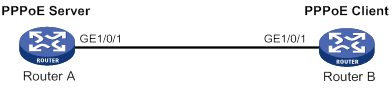
Configuration procedure
1. Configure Router A as the PPPoE server:
# Configure an IP address for Virtual-Template 1 and specify an IP address for the peer.
<RouterA> system-view
[RouterA] interface virtual-template 1
[RouterA-Virtual-Template1] ip address 1.1.1.1 255.0.0.0
[RouterA-Virtual-Template1] remote address 1.1.1.2
[RouterA-Virtual-Template1] quit
# Enable the PPPoE server on GigabitEthernet 1/0/1, and bind the interface to Virtual-Template 1.
[RouterA] interface gigabitethernet 1/0/1
[RouterA-GigabitEthernet1/0/1] pppoe-server bind virtual-template 1
[RouterA-GigabitEthernet1/0/1] quit
2. Configure Router B as the PPPoE client:
# Create dialer access group 1 and configure a dial access control rule for it.
<RouterB> system-view
[RouterB] dialer-group 1 rule ip permit
# Enable bundle DDR on Dialer 1.
[RouterB] interface dialer 1
[RouterB-Dialer1] dialer bundle enable
# Associate Dialer 1 with dialer access group 1.
[RouterB-Dialer1] dialer-group 1
[RouterB-Dialer1] quit
# Configure Dialer 1 to obtain an IP address through PPP negotiation.
[RouterB-Dialer1] ip address ppp-negotiate
# Configure a PPPoE session that corresponds to dialer bundle 1 (dialer bundle 1 corresponds to Dialer 1).
[RouterB] interface gigabitethernet 1/0/1
[RouterB-GigabitEthernet1/0/1] pppoe-client dial-bundle-number 1
[RouterB-GigabitEthernet1/0/1] quit
# Configure the PPPoE session to operate in permanent mode.
[RouterB] interface dialer 1
[RouterB-Dialer1] dialer timer idle 0
# Set the DDR auto-dial interval to 60 seconds.
[RouterB-Dialer1] dialer timer autodial 60
[RouterB-Dialer1] quit
# Configure a static route.
[RouterB] ip route-static 1.1.1.1 255.0.0.0 dialer 1
Verifying the configuration
# Display summary information about the PPPoE session established between Router B and Router A (PPPoE server).
[RouterB-Dialer1] display pppoe-client session summary
Bundle ID Interface VA RemoteMAC LocalMAC State
1 1 GE1/0/1 VA0 00e0-1400-4300 00e0-1500-4100 SESSION
PPPoE client in on-demand mode configuration example
Network requirements
As shown in Figure 17, Router A serves as a PPPoE server. Configure Router B as a PPPoE client operating in on-demand mode, and set the link idle-timeout timer to 150 seconds.
Configuration procedure
1. Configure Router A as the PPPoE server:
# Configure an IP address for Virtual-Template 1 and specify an IP address for the peer.
<RouterA> system-view
[RouterA] interface virtual-template 1
[RouterA-Virtual-Template1] ip address 1.1.1.1 255.0.0.0
[RouterA-Virtual-Template1] remote address 1.1.1.2
[RouterA-Virtual-Template1] quit
# Enable the PPPoE server on GigabitEthernet 1/0/1, and bind the interface to Virtual-Template 1.
[RouterA] interface gigabitethernet 1/0/1
[RouterA-GigabitEthernet1/0/1] pppoe-server bind virtual-template 1
[RouterA-GigabitEthernet1/0/1] quit
2. Configure Router B as the PPPoE client:
# Create dialer access group 1 and configure a dial access control rule for it.
<RouterB> system-view
[RouterB] dialer-group 1 rule ip permit
# Enable bundle DDR on Dialer 1.
[RouterB] interface dialer 1
[RouterB-Dialer1] dialer bundle enable
# Associate Dialer 1 with dialer access group 1.
[RouterB-Dialer1] dialer-group 1
[RouterB-Dialer1] quit
# Configure Dialer 1 to obtain an IP address through PPP negotiation.
[RouterB-Dialer1] ip address ppp-negotiate
# Configure a PPPoE session that corresponds to dialer bundle 1 (dialer bundle 1 corresponds to Dialer 1).
[RouterB] interface gigabitethernet 1/0/1
[RouterB-GigabitEthernet1/0/1] pppoe-client dial-bundle-number 1
[RouterB-GigabitEthernet1/0/1] quit
# Configure a static route.
[RouterB] ip route-static 1.1.1.1 255.0.0.0 dialer 1
# Set the link-idle timeout timer to 150 seconds.
[RouterB] interface dialer 1
[RouterB-Dialer1] dialer timer idle 150
[RouterB-Dialer1] quit
Verifying the configuration
# Display summary information about the PPPoE session established between Router B and Router A (PPPoE server).
[RouterB-Dialer1] display pppoe-client session summary
Bundle ID Interface VA RemoteMAC LocalMAC State
1 1 GE1/0/1 VA0 00e0-1400-4300 00e0-1500-4100 SESSION
PPPoE client in diagnostic mode configuration example
Network requirements
As shown in Figure 18, Router A serves as a PPPoE server. Configure Router B as a PPPoE client operating in diagnostic mode, and set the diagnostic interval to 200 seconds.
Configuration procedure
1. Configure Router A as the PPPoE server:
# Configure an IP address for Virtual-Template 1 and specify an IP address for the peer.
<RouterA> system-view
[RouterA] interface virtual-template 1
[RouterA-Virtual-Template1] ip address 1.1.1.1 255.0.0.0
[RouterA-Virtual-Template1] remote address 1.1.1.2
[RouterA-Virtual-Template1] quit
# Enable the PPPoE server on GigabitEthernet 1/0/1, and bind the interface to Virtual-Template 1.
[RouterA] interface gigabitethernet 1/0/
[RouterA-GigabitEthernet1/0/1] pppoe-server bind virtual-template 1
[RouterA-GigabitEthernet1/0/1] quit
2. Configure Router B as the PPPoE client:
# Create dialer access group 1 and configure a dial access control rule for it.
<RouterB> system-view
[RouterB] dialer-group 1 rule ip permit
# Enable bundle DDR on Dialer 1.
[RouterB] interface dialer 1
[RouterB-Dialer1] dialer bundle enable
# Associate Dialer 1 with dialer access group 1.
[RouterB-Dialer1] dialer-group 1
[RouterB-Dialer1] quit
# Configure Dialer 1 to obtain an IP address through PPP negotiation.
[RouterB-Dialer1] ip address ppp-negotiate
# Configure a PPPoE session that corresponds to dialer bundle 1 (dialer bundle 1 corresponds to Dialer 1).
[RouterB] interface gigabitethernet 1/0/1
[RouterB-GigabitEthernet1/0/1] pppoe-client dial-bundle-number 1
[RouterB-GigabitEthernet1/0/1] quit
# Configure the PPPoE session to operate in diagnostic mode, and set the diagnostic interval to 200 seconds.
[RouterB] interface dialer 1
[RouterB-Dialer1] dialer diagnose interval 200
# Set the DDR auto-dial interval to 10 seconds.
[RouterB-Dialer1] dialer timer autodial 10
Verifying the configuration
# Display summary information about the PPPoE session established between Router B and Router A (PPPoE server).
[RouterB-Dialer1] display pppoe-client session summary
Bundle ID Interface VA RemoteMAC LocalMAC State
1 1 GE1/0/1 VA0 00e0-1400-4300 00e0-1500-4100 SESSION
Configuration example for connecting a LAN to the Internet through an ADSL modem
Network requirements
As shown in Figure 19:
· Router A provides Internet access for Host A, Host B, and Host C. It connects to the DSLAM through an ADSL modem and a permanent PPPoE session.
· The username and password of the ADSL account are user1 and 123456.
· Router A operates as a PPPoE client, and it allows the hosts in the LAN to access the Internet without PPPoE client software.
· Router B operates as the PPPoE server. It performs RADIUS authentication and accounting.
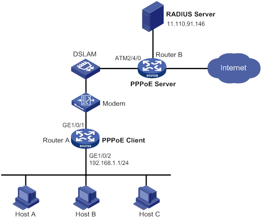
Configuration procedure
1. Configure Router A as a PPPoE client:
# Create dialer access group 1 and configure a dial access control rule for it.
<RouterA> system-view
[RouterA] dialer-group 1 rule ip permit
# Enable bundle DDR on Dialer 1.
[RouterA] interface dialer 1
[RouterA-Dialer1] dialer bundle enable
# Associate Dialer 1 with dialer access group 1.
[RouterA-Dialer1] dialer-group 1
# Configure Dialer 1 to obtain an IP address through PPP negotiation.
[RouterA-Dialer1] ip address ppp-negotiate
# Configure the PPPoE session to operate in permanent mode.
[RouterA-Dialer1] dialer timer idle 0
# Configure the PAP username and password.
[RouterA-Dialer1] ppp pap local-user user1 password simple 123456
[RouterA-Dialer1] quit
# Configure a PPPoE session.
[RouterA] interface gigabitethernet 1/0/1
[RouterA-GigabitEthernet1/0/1] pppoe-client dial-bundle-number 1
[RouterA-GigabitEthernet1/0/1] quit
# Configure an IP address for the LAN interface.
[RouterA] interface gigabitethernet 1/0/2
[RouterA-GigabitEthernet1/0/2] ip address 192.168.1.1 255.255.255.0
[RouterA-GigabitEthernet1/0/2] quit
# Configure a default route.
[RouterA] ip route-static 0.0.0.0 0 dialer 1
If the hosts in the LAN use private addresses, configure NAT on Router A. For more information about NAT, see Layer 3—IP Services Configuration Guide.
2. Configure Router B as the PPPoE server:
# Configure Virtual-Template 1 to use PAP for authentication and use a PPP address pool to assign IP addresses.
<RouterB> system-view
[RouterB] interface virtual-template 1
[RouterB-Virtual-Template1] ppp authentication-mode pap domain system
[RouterB-Virtual-Template1] remote address pool 1
[RouterB-Virtual-Template1] ip address 1.1.1.1 255.0.0.0
[RouterB-Virtual-Template1] quit
# Configure a local PPP address pool that contains nine assignable IP addresses.
[RouterB] ip pool 1 1.1.1.2 1.1.1.10
# Enable the PPPoE server on the Virtual-Ethernet 1.
[RouterB] interface virtual-ethernet 2/0/0
[RouterB-Virtual-Ethernet2/0/0] mac-address 0001-0000-0001
[RouterB-Virtual-Ethernet2/0/0] pppoe-server bind virtual-template 1
[RouterB-Virtual-Ethernet2/0/0] quit
# Configure an ATM interface.
[RouterB] interface atm 2/4/0.1
[RouterB-ATM2/4/0.1] pvc to_adsl_a 0/60
[RouterB-ATM2/4/0.1-pvc-to_adsl_a-0/60] map bridge virtual-ethernet 2/0/0
[RouterB-ATM2/4/0.1-pvc-to_adsl_a-0/60] quit
[RouterB-Atm2/4/0.1] quit
# Configure the default ISP domain (system) to use the RADIUS scheme for authentication, authorization, and accounting.
[RouterB] domain system
[RouterB-isp-system] authentication ppp radius-scheme cams
[RouterB-isp-system] authorization ppp radius-scheme cams
[RouterB-isp-system] accounting ppp radius-scheme cams
[RouterB-isp-system] quit
# Configure a RADIUS scheme, and assign an IP address and port number for the RADIUS server.
[RouterB] radius scheme cams
[RouterB-radius-cams] primary authentication 11.110.91.146 1812
[RouterB-radius-cams] primary accounting 11.110.91.146 1813
# Set the shared keys for secure communication with the RADIUS server to expert in plain text.
[RouterB-radius-cams] key authentication simple expert
[RouterB-radius-cams] key accounting simple expert
[RouterB-radius-cams] quit
3. Configure the RADIUS server:
# Configure the authentication and accounting passwords as expert.
# Add a PPPoE user with username user1 and password 123456.
For more information about RADIUS, see Security Configuration Guide.
Verifying the configuration
# Display summary information for the PPPoE session between Router A and Router B.
[RouterA] display pppoe-client session summary
Bundle ID Interface VA RemoteMAC LocalMAC State
1 1 GE1/0/1 VA0 0001-0000-0001 00e0-1500-4100 SESSION
Host A, Host B, and Host C can thus access the Internet. For example, they can browse a web page through IE.
Configuring L2TP
Overview
The Layer 2 Tunneling Protocol (L2TP) is a Virtual Private Dialup Network (VPDN) tunneling protocol. L2TP sets up point-to-point tunnels across a public network (for example, the Internet) and transmits encapsulated PPP frames (L2TP packets) over the tunnels. With L2TP, remote users can access the private networks through L2TP tunnels after connecting to a public network by using PPP.
As a Layer 2 VPN technology, L2TP provides a secure, cost-effective solution for remote users to access private networks.
Typical L2TP networking
Figure 20 L2TP network diagram
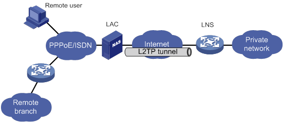
As shown in Figure 20, a typical L2TP network has the following components:
· Remote system—A remote system is usually a remote user's host or a remote branch's device that needs to access the private network.
· LAC—An L2TP access concentrator (LAC) is both PPP and L2TP capable. It is usually a network access server (NAS) located at a local ISP, which provides access services mainly for PPP users.
An LAC is an endpoint of an L2TP tunnel and lies between an LNS and a remote system. It encapsulates packets received from a remote system by using L2TP and then sends the encapsulated packets to the LNS. It decapsulates packets received from the LNS and then sends the decapsulated packets to the intended remote system.
· LNS—An L2TP network server (LNS) is both PPP and L2TP capable. It is usually an edge device on an enterprise network.
An LNS is the other endpoint of an L2TP tunnel. It is the logical termination point of a PPP session tunneled by the LAC. L2TP extends the termination point of a PPP session from a NAS to an LNS by establishing a tunnel.
L2TP message types and encapsulation structure
L2TP uses the following types of messages:
· Control messages—Used to establish, maintain, and delete L2TP tunnels and sessions. Control messages are transmitted over a reliable control channel, which supports flow control and congestion control.
· Data messages—Used to encapsulate PPP frames, as shown in Figure 21. Data messages are transmitted over an unreliable data channel and are not retransmitted when packet loss occurs. Data messages can use sequence numbers to reorder packets that are disordered during transport.
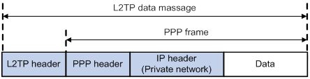
As shown in Figure 22, both control messages and data messages are encapsulated in UDP datagrams.
Figure 22 L2TP encapsulation structure
![]()
L2TP tunnel and session
An L2TP tunnel is a virtual point-to-point connection between an LAC and an LNS. Multiple L2TP tunnels can be established between an LNS and an LAC. An L2TP tunnel can carry one or more L2TP sessions. Each L2TP session corresponds to a PPP session and is multiplexed on an L2TP tunnel. An L2TP session is established between the LAC and LNS when an end-to-end PPP session is established between a remote system and the LNS. Data frames for the PPP session are transmitted over the tunnel between the LAC and LNS.
L2TP tunneling modes and tunnel establishment process
L2TP tunneling modes include NAS-initiated, client-initiated, and LAC-auto-initiated.
NAS-initiated tunneling mode
As shown in Figure 23, a remote system dials in to the LAC through a PPPoE/ISDN network. The LAC initiates a tunneling request to the LNS over the Internet.
Figure 23 NAS-initiated tunneling mode
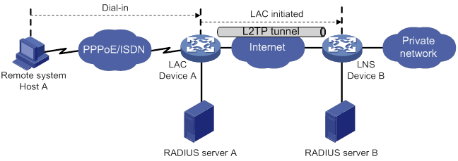
A NAS-initiated tunnel has the following characteristics:
· The remote system only needs to support PPP, and it does not need to support L2TP.
· Authentication and accounting of the remote system can be implemented on the LAC or LNS.
Figure 24 NAS-initiated tunnel establishment process
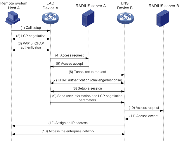
As shown in Figure 24, the following workflow is used to establish a NAS-initiated tunnel:
1. A remote system (Host A) initiates a PPP connection to the LAC (Device A).
2. The remote system and LAC perform PPP LCP negotiation.
3. The LAC authenticates PPP user information of Host A by using PAP or CHAP.
4. The LAC sends the authentication information (username and password) to its RADIUS server (RADIUS server A) for authentication.
5. RADIUS server A authenticates the user and returns the result.
6. The LAC initiates an L2TP tunneling request to the LNS (Device B) when the following conditions exist:
? The user passes the authentication.
? The user is determined to be an L2TP user according to the username or the ISP domain to which the user belongs.
7. If tunnel authentication is needed, the LAC and LNS send CHAP challenge messages to authenticate each other before successfully establishing an L2TP tunnel.
8. The LAC and LNS negotiate to establish L2TP sessions.
9. The LAC sends PPP user information and PPP negotiation parameters to the LNS.
10. The LNS sends the authentication information to its RADIUS server (RADIUS server B) for authentication.
11. RADIUS server B authenticates the user and returns the result.
12. If the user passes the authentication, the LNS assigns a private IP address to the remote system (Host A).
13. The PPP user can access internal resources of the enterprise.
In steps 12 and 13, the LAC forwards packets for the remote system and LNS. Host A and LAC exchange PPP frames, and the LAC and LNS exchange L2TP packets.
Client-initiated tunneling mode
As shown in Figure 25, a remote system running L2TP (LAC client) has a public IP address to communicate with the LNS through the Internet. The LAC client can directly initiate a tunneling request to the LNS without any dedicated LAC devices.
Figure 25 Client-initiated tunneling mode
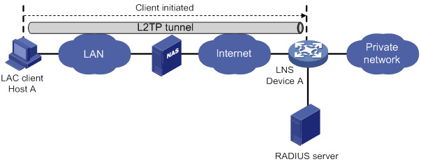
A client-initiated tunnel has the following characteristics:
· A client-initiated tunnel has higher security because it is established between a remote system and the LNS.
· The remote system must support L2TP and be able to communicate with the LNS. This causes poor expandability.
As shown in Figure 26, the workflow for establishing a client-initiated tunnel is similar to that for establishing a NAS-initiated tunnel. (Details not shown.)
Figure 26 Client-initiated tunnel establishment process
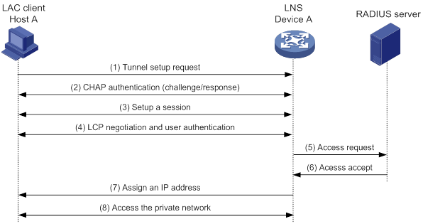
LAC-auto-initiated tunneling mode
In NAS-initiated mode, a remote system must successfully dial in to the LAC through PPPoE or ISDN.
In LAC-auto-initiated mode, you can use the l2tp-auto-client command on the LAC to trigger the LAC to initiate a tunneling request to the LNS. When a remote system accesses the private network, the LAC forwards data through the L2TP tunnel.
Figure 27 LAC-auto-initiated tunneling mode
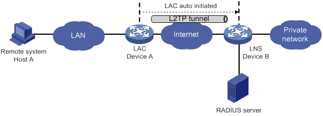
An LAC-auto-initiated tunnel has the following characteristics:
· The connection between a remote system and the LAC is not confined to a dial-up connection and can be any IP-based connection.
· An L2TP session is established immediately after an L2TP tunnel is established. Then, the LAC and LNS, acting as the PPPoE client and PPPoE server, respectively, perform PPP negotiation.
· An L2TP tunnel can carry only one L2TP session.
· The LNS assigns a private IP address to the LAC instead of to the remote system.
As shown in Figure 28, the workflow for establishing an LAC-auto-initiated tunnel is similar to that for establishing a NAS-initiated tunnel. (Details not shown.)
Figure 28 Establishment process for LAC-auto-initiated tunnels
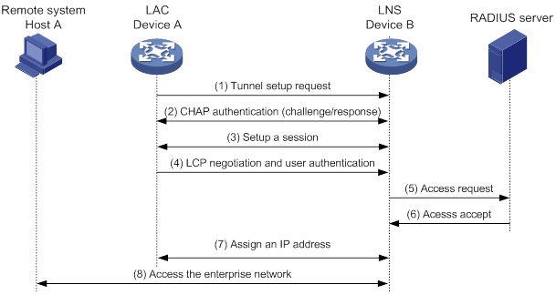
L2TP features
· Flexible identity authentication mechanism and high security—L2TP by itself does not provide security for connections. However, it has all the security features of PPP and allows for PPP authentication (CHAP or PAP). L2TP can also cooperate with IPsec to improve security for tunneled data.
· Multiprotocol transmission—L2TP tunnels PPP frames, which can be used to encapsulate packets of multiple network layer protocols.
· RADIUS authentication—An LAC or LNS can send the username and password of a remote user to a RADIUS server for authentication.
· Private address allocation—An LNS can dynamically allocate private addresses to remote users. This facilitates address allocation for private internets (RFC 1918) and improves security.
· Flexible accounting—Accounting can be simultaneously performed on the LAC and LNS. This allows bills to be generated on the ISP side and charging and auditing to be processed on the enterprise gateway. L2TP can provide accounting data, including inbound and outbound traffic statistics (in packets and bytes) and the connection's start time and end time. The AAA server uses these data for flexible accounting.
· Reliability—L2TP supports LNS backup. When the connection to the primary LNS is torn down, an LAC can establish a new connection to a secondary LNS. This redundancy enhances the reliability of L2TP services.
· Issuing tunnel attributes by RADIUS server to LAC—In NAS-initiated mode, the tunnel attributes can be issued by the RADIUS server to the LAC. For the LAC to receive these attributes, enable L2TP and configure remote AAA authentication for PPP users on the LAC.
When an L2TP user dials in to the LAC, the LAC as the RADIUS client sends the user information to the RADIUS server. The RADIUS server authenticates the PPP user, returns the result to the LAC, and issues L2TP tunnel attributes for the PPP user to the LAC. The LAC then sets up an L2TP tunnel and sessions based on the issued L2TP tunnel attributes.
Table 2 Tunnel attributes that can be issued by the RADIUS server
|
Attribute number |
Attribute name |
Description |
|
64 |
Tunnel-Type |
Tunnel type, which can only be L2TP. |
|
65 |
Tunnel-Medium-Type |
Transmission medium type for the tunnel, which can only be IPv4. |
|
67 |
Tunnel-Server-Endpoint |
IP address of the LNS. |
|
69 |
Tunnel-Password |
Key used to authenticate a peer of the tunnel. |
|
81 |
Tunnel-Private-Group-ID |
Group ID for the tunnel. The LAC sends this value to the LNS for the LNS to perform an operation accordingly. |
|
82 |
Tunnel-Assignment-ID |
Assignment ID for the tunnel. It is used to indicate the tunnel to which a session is assigned. L2TP users with the same Tunnel-Assignment-ID, Tunnel-Server-Endpoint, and Tunnel-Password attributes share an L2TP tunnel. |
|
90 |
Tunnel-Client-Auth-ID |
Tunnel name. It is used to indicate the local tunnel. |
The RADIUS server can issue only one set of the L2TP tunnel attributes in a RADIUS packet.
The RADIUS-issued tunnel attributes override the tunnel attributes manually configured on the LAC, but not vice versa.
· L2TP tunnel switching—Also called multihop L2TP tunneling. As shown in Figure 29, the Layer 2 tunnel switch (LTS) terminates L2TP packets from each LAC as an LNS. It then sends these packets to a destination LNS as an LAC.
L2TP tunnel switching has the following features:
? Simplified configuration and deployment—When LACs and LNSs are in different management domains:
- All LACs consider the LTS as an LNS and do not need to differentiate LNSs on the network.
- All LNSs consider the LTS as an LAC and are not affected by the addition or deletion of LACs.
? L2TP tunnel sharing—Different users can share the same L2TP tunnel between the LAC and the LTS. The LTS distributes data of different users to different LNSs.
Figure 29 L2TP tunnel switching network diagram
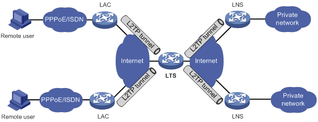
L2TP-based EAD
EAD authenticates PPP users that pass the access authentication. PPP users that pass EAD authentication can access network resources. PPP users that fail EAD authentication can only access the resources in the quarantine areas.
EAD uses the following procedure:
1. The iNode client uses L2TP to access the LNS. After the client passes the PPP authentication, the CAMS/IMC server assigns isolation ACLs to the LNS. The LNS uses the isolation ACLs to filter incoming packets.
2. After the IPCP negotiation, the LNS sends the IP address of the CAMS/IMC server to the iNode client. The server IP address is permitted by the isolation ACLs.
3. The CAMS/IMC server authenticates the iNode client and performs security check for the iNode client. If the iNode client passes security check, the CAMS/IMC server assigns security ACLs for the iNode client to the LNS. The iNode client can access network resources.
Protocols and standards
· RFC 1661, The Point-to-Point Protocol (PPP)
· RFC 1918, Address Allocation for Private Internets
· RFC 2661, Layer Two Tunneling Protocol "L2TP"
· RFC 2868, RADIUS Attributes for Tunnel Protocol Support
Feature and hardware compatibility
The device does not support this feature in IRF mode.
The LNS mode is not supported on MSR810-LMS and MSR810-LUS routers.
L2TP configuration task list
When you configure L2TP, perform the following tasks:
1. Determine the network devices needed according to the networking environment.
? For NAS-initiated mode and LAC-auto-initiated mode, configure both the LAC and the LNS.
? For client-initiated mode, you only need to configure the LNS.
2. Configure the devices based on the intended role (LAC or LNS) on the network.
To configure a device as an LAC in NAS-initiated or LAC-auto-initiated mode, complete the following tasks:
|
Tasks at a glance |
Remarks |
|
(Required.) Configuring basic L2TP capabilities |
N/A |
|
· (Required.) Configuring an LAC to initiate tunneling requests for a user · (Required.) Specifying LNS IP addresses · (Optional) Configuring the source IP address of L2TP tunnel packets · (Optional.) Enabling transferring AVP data in hidden mode · (Required.) Configuring AAA authentication on an LAC · (Required.) Configuring an LAC to automatically establish an L2TP tunnel |
The first and fifth tasks are required for NAS-initiated mode and unnecessary for LAC-auto-initiated mode. The last task is required for LAC-auto-initiated mode and unnecessary for NAS-initiated mode. |
|
(Optional.) Configuring optional L2TP parameters: · Configuring L2TP tunnel authentication · Enabling session flow control · Setting the DSCP value of L2TP packets · Assigning a tunnel peer to a VPN |
N/A |
|
(Optional.) Configuring IMSI/SN binding authentication |
N/A |
To configure a device as an LNS in NAS-initiated, client-initiated, or LAC-auto-initiated mode, complete the following tasks:
|
Tasks at a glance |
|
(Required.) Configuring basic L2TP capabilities |
|
· (Required.) Creating a VT interface · (Optional.) Configuring a VA pool · (Required.) Configuring an LNS to accept L2TP tunneling requests from an LAC · (Optional.) Configuring user authentication on an LNS · (Optional.) Configuring AAA authentication on an LNS |
|
(Optional.) Configuring optional L2TP parameters: · Configuring L2TP tunnel authentication · Enabling session flow control · Setting the DSCP value of L2TP packets |
|
(Optional.) Enabling L2TP-based EAD |
|
(Optional.) Configuring IMSI/SN binding authentication |
Configuring basic L2TP capabilities
Basic L2TP capability configuration includes the following tasks:
· Enabling L2TP—L2TP must be enabled for L2TP configurations to take effect.
· Creating an L2TP group—An L2TP group is intended to represent a group of parameters. This enables not only flexible L2TP configuration on devices, but also one-to-one and one-to-many networking applications for LACs and LNSs. An L2TP group has local significance only. However, the relevant settings of the L2TP groups on the LAC and LNS must match. For example, the local tunnel name configured on the LAC must match the tunnel peer name configured on the LNS.
· Configuring the local tunnel name—The local tunnel name identifies the tunnel at the local end during tunnel negotiation between an LAC and an LNS.
To configure basic L2TP capabilities:
|
Step |
Command |
Remarks |
|
1. Enter system view. |
system-view |
N/A |
|
2. Enable L2TP. |
l2tp enable |
By default, L2TP is disabled. |
|
3. Create an L2TP group, specify its mode, and enter its view. |
l2tp-group group-number mode { lac | lns } |
By default, no L2TP group is created. Specify the mode as lac on the LAC side and as lns on the LNS side. |
|
4. Specify the local tunnel name. |
tunnel name name |
Optional. By default, the device name is used. |
Configuring an LAC
An LAC establishes tunnels with LNSs and forwards packets between LNSs and remote systems.
Configuring an LAC to initiate tunneling requests for a user
This task configures an LAC to initiate tunneling requests to an LNS for a user. When the PPP user information matches the specified user, the LAC determines that the PPP user is an L2TP user and initiates tunneling requests to the LNS.
You can specify a user by configuring one of the following items:
· Fully qualified name—The LAC initiates tunneling requests to the LNS only if the username of a PPP user matches the configured fully qualified name.
· Domain name—The LAC initiates tunneling requests to the LNS only if the ISP domain name of a PPP user matches the configured domain name.
To configure an LAC to initiate tunneling requests for a user:
|
Step |
Command |
Remarks |
|
1. Enter system view. |
system-view |
N/A |
|
2. Enter L2TP group view in LAC mode. |
l2tp-group group-number [ mode lac ] |
N/A |
|
3. Configure the LAC to initiate tunneling requests for a user. |
user { domain domain-name | fullusername user-name } |
By default, an LAC does not initiate tunneling requests for any users. |
Specifying LNS IP addresses
You can specify up to five LNS IP addresses. The LAC initiates an L2TP tunneling request to its specified LNSs consecutively in their configuration order until it receives an acknowledgment from an LNS. That LNS then becomes the tunnel peer.
To specify LNS IP addresses:
|
Step |
Command |
Remarks |
|
1. Enter system view. |
system-view |
N/A |
|
2. Enter L2TP group view in LAC mode. |
l2tp-group group-number [ mode lac ] |
N/A |
|
3. Specify LNS IP addresses. |
lns-ip { ip-address }&<1-5> |
By default, no LNS IP addresses are specified. |
Configuring the source IP address of L2TP tunnel packets
As a best practice to ensure high availability, use the IP address of a loopback interface as the source IP address of L2TP tunnel packets on the LAC. If equal cost routing paths exist between the LAC and LNS, you must use the IP address of a loopback interface as the source IP address of L2TP tunnel packets. To do so, use the source-ip command or use the RADIUS server to assign a loopback interface address.
To configure the source IP address of L2TP tunnel packets:
|
Step |
Command |
Remarks |
|
1. Enter system view. |
system-view |
N/A |
|
2. Enter L2TP group view in LAC mode. |
l2tp-group group-number [ mode lac ] |
N/A |
|
3. Configure the source IP address of L2TP tunnel packets. |
source-ip ip-address |
By default, the source IP address of L2TP tunnel packets is the IP address of the egress interface. |
Enabling transferring AVP data in hidden mode
L2TP uses Attribute Value Pairs (AVPs) to transmit tunnel negotiation parameters, session negotiation parameters, and user authentication information. Transferring AVP data in hidden mode can hide sensitive AVP data such as user passwords. This feature encrypts AVP data with the key configured by using the tunnel password command before transmission.
This configuration takes effect only when the tunnel authentication feature is enabled. For more information about configuring tunnel authentication, see "Configuring L2TP tunnel authentication."
To enable transferring AVP data in hidden mode:
|
Step |
Command |
Remarks |
|
1. Enter system view. |
system-view |
N/A |
|
2. Enter L2TP group view in LAC mode. |
l2tp-group group-number [ mode lac ] |
N/A |
|
3. Enable transferring AVP data in hidden mode. |
tunnel avp-hidden |
By default, AVP data is transferred in plain text. |
Configuring AAA authentication on an LAC
You can configure AAA authentication an LAC to authenticate the remote dialup users and initiate a tunneling request only for qualified users. A tunnel will not be established for unqualified users.
The device supports both local AAA authentication and remote AAA authentication.
· For local AAA authentication, create a local user and configure a password for each remote user on the LAC. The LAC then authenticates a remote user by matching the provided username and password with those configured locally.
· For remote AAA authentication, configure the username and password of each user on the RADIUS/HWTACACS server. The LAC then sends the remote user's username and password to the server for authentication.
For more information about configuring AAA authentication, see Security Configuration Guide.
To enable AAA authentication on an LAC, you also need to configure PAP or CHAP authentication for PPP users on the user access interfaces. For information about configuring PAP or CHAP, see "Configuring PPP and MP."
Configuring an LAC to automatically establish an L2TP tunnel
To configure an LAC to automatically establish an L2TP tunnel, perform the following tasks:
· Create a virtual PPP interface and configure an IP address for the interface.
· In virtual PPP interface view, use the ppp pap or ppp chap command to configure the side to be authenticated by PPP as follows:
? Specify the PPP authentication method for the PPP user.
? Configure the username and password of the PPP user.
The LNS then authenticates the PPP user. For more information, see "Configuring PPP and MP."
· Trigger the LAC to automatically establish an L2TP tunnel.
To configure an LAC to automatically establish an L2TP tunnel:
|
Step |
Command |
Remarks |
|
1. Enter system view. |
system-view |
N/A |
|
2. Create a virtual PPP interface and enter its view. |
interface virtual-ppp interface-number |
By default, no virtual PPP interface is created. |
|
3. Configure the IP address of the virtual PPP interface. |
·
Assign an IP address to the virtual PPP
interface. ·
Enable IP address negotiation on the virtual
PPP interface. |
By default, no IP address is configured. |
|
4. Configure the peer to be authenticated. |
See "Configuring PPP and MP." |
N/A |
|
5. Configure the LAC to automatically establish an L2TP tunnel with the LNS. |
l2tp-auto-client l2tp-group group-number |
By default, an LAC does not establish an L2TP tunnel. An L2TP tunnel automatically established in LAC-auto-initiated mode exists until you remove the tunnel by using the undo l2tp-auto-client or undo l2tp-group group-number command. |
|
6. (Optional.) Set the description for the interface. |
description text |
By default, the description of an interface is in the format of interface-name Interface, for example, Virtual-PPP254 Interface. |
|
7. Set the MTU size of the interface. |
mtu size |
The default setting is 1500 bytes. |
|
8. (Optional.) Set the keepalive interval. |
timer-hold seconds |
The default setting is 10 seconds. |
|
9. (Optional.) Set the keepalive retry limit. |
timer-hold retry retries |
The default setting is 5. |
|
10. (Optional.) Specify a primary traffic processing slot for the interface (distributed devices in standalone mode). |
service slot slot-number |
By default, no primary traffic processing slot is specified for an interface. |
|
11. (Optional.) Specify a backup traffic processing slot for the interface (distributed devices in standalone mode). |
service standby slot |
By default, no backup traffic processing slot is specified for an interface. |
|
12. (Optional.) Set the expected bandwidth for the interface. |
bandwidth bandwidth-value |
By default, the expected bandwidth (in kbps) is interface baudrate divided by 1000. |
|
13. (Optional.) Restore the default settings for the interface. |
default |
N/A |
|
14. (Optional.) Bring up the interface. |
undo shutdown |
By default, an interface is up. |
Configuring an LNS
An LNS responds to the tunneling requests from an LAC, authenticates users, and assigns IP addresses to users.
Creating a VT interface
After an L2TP session is established, a virtual access (VA) interface is needed for data exchange with the peer. The system will dynamically create VA interfaces based on the parameters of the virtual template (VT) interface. To configure an LNS, first create a VT interface and configure the following parameters for it:
· Interface IP address.
· Authentication mode for PPP users.
· IP addresses allocated by the LNS to PPP users.
For information about configuring VT interfaces, see "Configuring PPP and MP" and Layer 3—IP Services Configuration Guide.
Configuring a VA pool
A VA pool contains a group of VA interfaces. You can configure a VA pool to improve the performance of establishing or terminating L2TP connections. The LNS selects a VA interface from the pool for a requesting user and releases the VA interface when the user goes offline. When a VA pool is exhausted, the system creates a VA interface for an L2TP connection and deletes it when the user goes offline.
Configuration guidelines
When you configure a VA pool, follow these guidelines:
· A VT interface can be associated with only one VA pool. To change the capacity of a VA pool, delete the previous configuration and reconfigure the VA pool.
· Creating or deleting a VA pool takes time. During the process of creating or deleting a VA pool, users can come online or go offline, but the VA pool does not take effect.
· The system might create a VA pool that contains VA interfaces less than the specified number because of insufficient resources. To view the number of available VA interfaces and the current state of the VA pool, use the display l2tp va-pool command.
· Create a VA pool with an appropriate capacity, because a VA pool occupies much system memory.
· Deleting a VA pool does not log off the users who are using VA interfaces in the VA pool.
Configuration procedure
To configure a VA pool:
|
Step |
Command |
Remarks |
|
1. Enter system view. |
system-view |
N/A |
|
2. Create a VA pool. |
l2tp virtual-template template-number va-pool va-volume |
By default, no VA pool is created. |
Configuring an LNS to accept L2TP tunneling requests from an LAC
When receiving a tunneling request, an LNS performs the following operations:
· Determines whether to accept the tunneling request by checking whether the name of the tunnel peer (LAC) matches the one configured.
· Determines the VT interface to be used for creating the VA interface.
To configure an LNS to accept L2TP tunneling requests from an LAC:
|
Step |
Command |
Remarks |
|
|
1. Enter system view. |
system-view |
N/A |
|
|
2. Enter L2TP group view in LNS mode. |
l2tp-group group-number [ mode lns ] |
N/A |
|
|
3. Configure the LNS to accept tunneling requests from an LAC and specify the VT interface to be used for tunnel setup. |
·
If the L2TP group number is 1: ·
If the L2TP group number is not 1: |
By default, an LNS denies tunneling requests from any LAC. If the L2TP group number is 1, the remote remote-name option is optional. If you do not specify this option, the LNS accepts tunneling requests from any LAC. |
|
Configuring user authentication on an LNS
An LNS can be configured to authenticate a user that has passed authentication on the LAC to increase security. In this case, the user is authenticated once on the LAC and once on the LNS. An L2TP tunnel can be established only when both authentications succeed.
An LNS provides the following authentication methods in ascending order of priority:
· Proxy authentication—The LNS uses the LAC as an authentication proxy. The LAC sends the LNS all user authentication information from users and the authentication method configured on the LAC itself. The LNS then checks the user validity according to the received information and the locally configured authentication method.
· Mandatory CHAP authentication—The LNS uses CHAP authentication to reauthenticate users who have passed authentication on the LAC.
· LCP renegotiation—The LNS ignores the LAC proxy authentication information and performs a new round of LCP negotiation with the user.
The LNS chooses an authentication method depending on your configuration.
· If you configure both LCP renegotiation and mandatory CHAP authentication, the LNS uses LCP renegotiation.
· If you configure only mandatory CHAP authentication, the LNS performs CHAP authentication for users after proxy authentication succeeds.
· If you configure neither LCP renegotiation nor mandatory CHAP authentication, the LNS uses the LAC for proxy authentication.
Configuring mandatory CHAP authentication
When mandatory CHAP authentication is configured, a user who uses an LAC to initiate tunneling requests is authenticated by both the LAC and the LNS. Some users might not support the authentication on the LNS. In this situation, do not enable this feature, because CHAP authentication on the LNS will fail.
For this feature to take effect, you must also configure CHAP authentication for the PPP user on the VT interface of the LNS.
To configure mandatory CHAP authentication:
|
Step |
Command |
Remarks |
|
1. Enter system view. |
system-view |
N/A |
|
2. Enter L2TP group view in LNS mode. |
l2tp-group group-number [ mode lns ] |
N/A |
|
3. Configure mandatory CHAP authentication. |
mandatory-chap |
By default, CHAP authentication is not performed on an LNS. This command is effective only on NAS-initiated L2TP tunnels. |
Configuring LCP renegotiation
To establish a NAS-initiated L2TP tunnel, a user first negotiates with the LAC at the start of a PPP session. If the negotiation succeeds, the LAC initiates an L2TP tunneling request and sends user information to the LNS. The LNS then authenticates the user according to the proxy authentication information received.
For the LNS not to accept LCP negotiation parameters, configure this feature to perform a new round of LCP negotiation between the LNS and the user. In this case, the LNS authenticates the user by using the authentication method configured on the corresponding VT interface.
If you enable LCP renegotiation but configure no authentication for the corresponding VT interface, the LNS does not perform an additional authentication for users.
To configure the LNS to perform LCP renegotiation with users:
|
Step |
Command |
Remarks |
|
1. Enter system view. |
system-view |
N/A |
|
2. Enter L2TP group view in LNS mode. |
l2tp-group group-number [ mode lns ] |
N/A |
|
3. Configure the LNS to perform LCP renegotiation with users. |
mandatory-lcp |
By default, an LNS does not perform LCP renegotiation with users. This command is effective only on NAS-initiated L2TP tunnels. |
Configuring AAA authentication on an LNS
After you configure AAA authentication on an LNS, the LNS can authenticate the usernames and passwords of remote access users. If a user passes AAA authentication, the user can communicate with the LNS to access the private network.
Configure AAA authentication on the LNS in one of the following cases:
· LCP renegotiation is not configured in NAS-initiated mode.
· The VT interface is configured with PPP user authentication and LCP renegotiation is configured in NAS-initiated mode.
· The VT interface is configured with PPP user authentication in client-initiated mode or LAC-auto-initiated mode.
LNS side AAA configurations are similar to those on an LAC (see "Configuring AAA authentication on an LAC").
Configuring optional L2TP parameters
The optional L2TP parameter configuration tasks apply to both LACs and LNSs.
Configuring L2TP tunnel authentication
Tunnel authentication allows the LAC and LNS to authenticate each other. Either the LAC or the LNS can initiate a tunnel authentication request.
You can enable tunnel authentication on both sides or either side.
To ensure a successful tunnel establishment when tunnel authentication is enabled on both sides or either side, set the same non-null key on the LAC and the LNS. To set the tunnel authentication key, use the tunnel password command.
When neither side is enabled with tunnel authentication, the key settings of the LAC and the LNS do not affect the tunnel establishment.
To ensure tunnel security, enable tunnel authentication.
For the tunnel authentication key change to take effect, change the tunnel authentication key before tunnel negotiation is performed.
To configure L2TP tunnel authentication:
|
Step |
Command |
Remarks |
|
1. Enter system view. |
system-view |
N/A |
|
2. Enter L2TP group view. |
l2tp-group group-number [ mode { lac | lns } ] |
N/A |
|
3. Enable L2TP tunnel authentication. |
tunnel authentication |
By default, L2TP tunnel authentication is enabled. |
|
4. Set the tunnel authentication key. |
tunnel password { cipher | simple } string |
By default, no key is set. |
Setting the Hello interval
To check the connectivity of a tunnel, the LAC and LNS periodically send each other Hello packets. At receipt of a Hello packet, the LAC or LNS returns a response packet. If the LAC or LNS receives no response packets from the peer within the Hello interval, it retransmits the Hello packet. If it receives no response packets from the peer after transmitting the Hello packet five times, it considers the L2TP tunnel to be down.
To set the Hello interval:
|
Step |
Command |
Remarks |
|
1. Enter system view. |
system-view |
N/A |
|
2. Enter L2TP group view. |
l2tp-group group-number [ mode { lac | lns } ] |
N/A |
|
3. Set the Hello interval. |
tunnel timer hello hello-interval |
The default setting is 60 seconds. |
Enabling session flow control
This feature adds sequence numbers to transmitted packets and uses them to reorder packets arriving out of order and to detect lost packets.
This feature takes effect on both sent and received L2TP data messages. The L2TP sessions support this feature if either the LAC or LNS is enabled with this feature.
To enable session flow control:
|
Step |
Command |
Remarks |
|
1. Enter system view. |
system-view |
N/A |
|
2. Enter L2TP group view. |
l2tp-group group-number [ mode { lac | lns } ] |
N/A |
|
3. Enable the session flow control feature. |
tunnel flow-control |
By default, this feature is disabled. |
Setting the DSCP value of L2TP packets
The DSCP field is the first 6 bits of the IP ToS byte. This field marks the priority of IP packets for forwarding. This feature sets the DSCP value for the IP packet when L2TP encapsulates a PPP frame into an IP packet.
To set the DSCP value of L2TP packets:
|
Step |
Command |
Remarks |
|
1. Enter system view. |
system-view |
N/A |
|
2. Enter L2TP group view. |
l2tp-group group-number [ mode { lac | lns } ] |
N/A |
|
ip dscp dscp-value |
The default setting is 0. |
Assigning a tunnel peer to a VPN
By default, the device transmits L2TP control messages and data messages over the public network. With this feature, the device transmits them in a VPN by searching the routing table in the VPN.
When one L2TP endpoint is in a VPN, assign the peer endpoint to the VPN for correct packet forwarding between the two endpoints.
To assign the tunnel peer to a VPN:
|
Step |
Command |
Remarks |
|
1. Enter system view. |
system-view |
N/A |
|
2. Enter L2TP group view. |
l2tp-group group-number [ mode { lac | lns } ] |
N/A |
|
3. Assign the tunnel peer to a VPN. |
vpn-instance vpn-instance-name |
By default, a tunnel peer belongs to the public network. The tunnel peer and the physical port connecting to the tunnel peer should belong to the same VPN. The VPN to which this physical port belongs is configured by using the ip binding vpn-instance command. |
Setting the TSA ID of the LTS
To detect loops, the LTS compares the configured TSA ID with each TSA ID AVP in a received ICRQ packet.
· If a match is found, a loop exists. The LTS immediately tears down the session.
· If no match is found, the LTS performs the following operations:
? Encapsulates the configured TSA ID into a new TSA ID AVP.
? Appends it to the packet.
? Sends the packet to the next hop LTS.
To avoid loop detection errors, make sure the TSA ID of each LTS is unique.
To set the TSA ID of the LTS:
|
Step |
Command |
Remarks |
|
1. Enter system view. |
system-view |
N/A |
|
2. Set the TSA ID of the LTS and enable L2TP loop detection on the LTS. |
l2tp tsa-id tsa-id |
By default, the TSA ID of the LTS is not configured, and L2TP loop detection is disabled on the LTS. |
Setting the sending window size for an L2TP tunnel
The packet processing capability of a peer end might mismatch the receiving window size of the peer end in some networks. For example, the actual packet processing capability of the peer end is 10, but the receiving window size of the peer end is 20. To ensure stable L2TP services, you can adjust the sending window size for the device to match the actual packet processing capability of the peer end.
The sending window size set in L2TP group view is obtained in the L2TP tunnel establishment process.
· If the sending window size is 0, the device uses the default sending window size.
· If the sending window size is not 0, the device uses the specified value as the sending window size.
Changing the sending window size after an L2TP tunnel is established does not affect the established L2TP tunnel.
To set the sending window size for an L2TP tunnel:
|
Step |
Command |
Remarks |
|
1. Enter system view. |
system-view |
N/A |
|
2. Enter L2TP group view. |
l2tp-group group-number [ mode { lac | lns } ] |
N/A |
|
3. Set the sending window size for the L2TP tunnel. |
tunnel window send size |
By default, the sending window size for an L2TP tunnel is 0, which means using the value of the receiving window size carried in messages sent by the peer end in the tunnel establishment process. If the messages from the peer end carry no receiving window size in the tunnel establishment process, the sending window size for the device is 4. |
Enabling L2TP-based EAD
Configuration guidelines
Follow these guidelines when you configure L2TP-based EAD:
· EAD authentication fails if no ACLs or rules are configured on the CAMS/IMC server even if EAD is enabled on the LNS.
· The LNS can use different ACLs to filter packets from different iNode clients.
· As a best practice, use EAD authentication for iNode clients on the Internet and use Portal authentication for iNode clients on a LAN.
Configuration prerequisites
Make sure Portal, AAA, RADIUS, and the security service server are configured as required before you enable L2TP-based EAD. For more information about AAA, RADIUS, and Portal, see Security Configuration Guide. For more information about the security service configuration, see CAMS EAD help and iMC EAD help.
Configuration procedure
|
Step |
Command |
Remarks |
|
1. Enter system view. |
system-view |
N/A |
|
2. Create a VT interface and enter its view |
interface virtual-template interface-number |
N/A |
|
3. Enable L2TP-based EAD. |
ppp access-control enable |
By default, L2TP-based EAD is disabled. |
Configuring IMSI/SN binding authentication
Configuring IMSI/SN binding authentication on the LNS
Configure this feature on the LNS in either of the following conditions:
· A 3G or 4G router acts as a client and accesses the LNS in client-initiated mode.
· A 4G router acts as an LAC and is automatically triggered to access the LNS in LAC-auto-initiated mode.
To configure IMSI/SN binding authentication on the LNS:
|
Step |
Command |
Remarks |
|
1. Enter system view. |
system-view |
N/A |
|
2. Enter VT interface view. |
interface virtual-template interface-number |
N/A |
|
3. Configure IMSI/SN binding authentication information. |
·
(Method 1) Enable the LNS to initiate IMSI/SN
binding authentication requests. ·
(Method 2) Configure the separator for
the received authentication information. |
Use one of the methods. By default, the LNS does not initiate IMSI/SN binding authentication requests and no separator is configured for the received authentication information |
|
4. (Optional.) Replace the client username with the IMSI or SN information for authentication. |
ppp user replace { imsi | sn } |
By default, the client username is used for authentication. |
Configuring IMSI/SN binding authentication on the LAC
This feature is supported only when the device acts as a 4G router. Whether the device can act as a 4G router depends on the device model.
When the 4G router acts as an LAC that is triggered to initiate tunneling requests to the LNS by using the LAC-auto-initiated mode, configure IMSI/SN binding authentication on the LAC. For more information about 4G routers, see "Managing a 3G/4G modem".
To configure IMSI/SN binding authentication on the LAC:
|
Step |
Command |
Remarks |
|
1. Enter system view. |
system-view |
N/A |
|
2. Create a virtual PPP interface and enter its view. |
interface virtual-ppp interface-number |
By default, no virtual PPP interface exists. |
|
3. Enable the LAC to accept the IMSI binding authentication requests from the LNS. |
ppp lcp imsi accept |
By default, the LAC does not accept IMSI binding authentication requests. |
|
4. Enable the LAC to accept the SN binding authentication requests from the LNS. |
ppp lcp sn accept |
By default, the LAC does not accept SN binding authentication requests. |
|
5. Configure the separator for the sent authentication information. |
ppp user attach-format imsi-sn split splitchart |
By default, no separator is configured for the sent authentication information. |
|
6. (Optional.) Configure the IMSI information on the LAC. |
ppp lcp imsi string imsi-info |
By default, the LAC automatically obtains the IMSI information from the device. |
|
7. (Optional.) Configure the SN information on the LAC. |
ppp lcp sn string sn-info |
By default, the LAC automatically obtains the SN information from the device. |
|
8. Return to system view. |
quit |
N/A |
|
9. Enter cellular interface view. |
controller cellular cellular-number |
N/A |
|
10. Bind the IMSI of the local SIM card to the virtual PPP interface. |
imsi bind virtual-ppp interface-number |
By default, the IMSI of the local SIM card is not bound to any interface. |
Configuring IMSI/SN binding authentication on the client
This feature is supported only when the device acts as a 3G or 4G router. Whether the device can act as a 4G router depends on the device model. For more information about 3G and 4G routers, see "Managing a 3G/4G modem".
To configure IMSI/SN binding authentication on the client:
|
Step |
Command |
Remarks |
|
1. Enter system view. |
system-view |
N/A |
|
2. Enter serial interface view. |
interface serial cellular-number:set-number |
A serial interface is channelized form a cellular interface by using the serial-set command. |
|
3. Enable the client to accept the IMSI binding authentication requests from the LNS. |
ppp lcp imsi accept |
By default, the client does not accept IMSI binding authentication requests. |
|
4. Enable the client to accept the SN binding authentication requests from the LNS. |
ppp lcp sn accept |
By default, the client does not accept SN binding authentication requests. |
|
5. (Optional.) Configure the IMSI information on the client. |
ppp lcp imsi string imsi-info |
By default, the client automatically obtains the IMSI information from the device. |
|
6. (Optional.) Configure the SN information on the client. |
ppp lcp sn string sn-info |
By default, the client automatically obtains the SN information from the device. |
|
7. (Optional.) Configure the separator for the sent authentication information. |
ppp user attach-format imsi-sn split splitchart |
By default, no separator is configured for the sent authentication information. |
Displaying and maintaining L2TP
Execute display commands in any view and reset commands in user view.
|
Task |
Command |
|
Display L2TP tunnel information. |
display l2tp tunnel [ statistics ] |
|
Display L2TP session information. |
display l2tp session [ statistics ] |
|
Display information about temporary L2TP sessions. |
display l2tp session temporary |
|
Display information about virtual PPP interfaces. |
display interface [ virtual-ppp [ interface-number ] ] [ brief [ description | down ] ] |
|
Display information about L2TP VA pools. |
display l2tp va-pool |
|
Disconnect an L2TP tunnel. |
reset l2tp tunnel { id tunnel-id | name remote-name } |
|
Clear the statistics for virtual PPP interfaces. |
reset counters interface [ virtual-ppp [ interface-number ] ] |
L2TP configuration examples
Configuration example for NAS-initiated L2TP tunnel
Network requirements
As shown in Figure 30, a PPP user is connected to an LNS through an LAC.
Set up an L2TP tunnel between the LAC and LNS to allow the PPP user to access the corporate network.
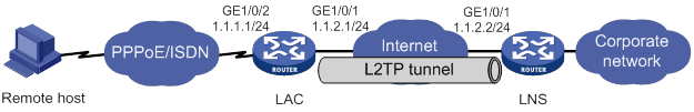
Configuration procedure
1. Configure the LAC:
# Configure IP addresses for the interfaces. (Details not shown.)
# Create a local user named vpdnuser, set the password, and enable the PPP service.
<LAC> system-view
[LAC] local-user vpdnuser class network
[LAC-luser-network-vpdnuser] password simple Hello
[LAC-luser-network-vpdnuser] service-type ppp
[LAC-luser-network-vpdnuser] quit
# Configure local authentication for PPP users in ISP domain system.
[LAC] domain system
[LAC-isp-system] authentication ppp local
[LAC-isp-system] quit
# Configure CHAP authentication on interface Virtual-Template 1.
[LAC] interface virtual-template 1
[LAC-Virtual-Template1] ppp authentication-mode chap domain system
[LAC-Virtual-Template1] quit
# Enable the PPPoE server on GigabitEthernet 1/0/2, and bind the interface to interface Virtual-Template 1.
[LAC] interface gigabitethernet 1/0/2
[LAC-GigabitEthernet1/0/2] pppoe-server bind virtual-template 1
[LAC-GigabitEthernet1/0/2] quit
# Enable L2TP.
[LAC] l2tp enable
# Create L2TP group 1 in LAC mode.
[LAC] l2tp-group 1 mode lac
# Configure the local tunnel name as LAC.
[LAC-l2tp1] tunnel name LAC
# Specify PPP user vpdnuser as the condition for the LAC to initiate tunneling requests.
[LAC-l2tp1] user fullusername vpdnuser
# Specify the LNS IP address as 1.1.2.2.
[LAC-l2tp1] lns-ip 1.1.2.2
# Enable tunnel authentication, and specify the tunnel authentication key as aabbcc.
[LAC-l2tp1] tunnel authentication
[LAC-l2tp1] tunnel password simple aabbcc
[LAC-l2tp1] quit
2. Configure the LNS:
# Configure IP addresses for the interfaces. (Details not shown.)
# Create a local user named vpdnuser, set the password, and enable the PPP service.
<LNS> system-view
[LNS] local-user vpdnuser class network
[LNS-luser-network-vpdnuser] password simple Hello
[LNS-luser-network-vpdnuser] service-type ppp
[LNS-luser-network-vpdnuser] quit
# Configure local authentication for PPP users in ISP domain system.
[LNS] domain system
[LNS-isp-system] authentication ppp local
[LNS-isp-system] quit
# Enable L2TP.
[LNS] l2tp enable
# Create a PPP address pool.
[LNS] ip pool aaa 192.168.0.10 192.168.0.20
[LNS] ip pool aaa gateway 192.168.0.1
# Create Virtual-Template 1, specify its PPP authentication mode as CHAP, and use address pool aaa to assign IP addresses to the PPP users.
[LNS] interface virtual-template 1
[LNS-virtual-template1] ppp authentication-mode chap domain system
[LNS-virtual-template1] remote address pool aaa
[LNS-virtual-template1] quit
# Create L2TP group 1 in LNS mode.
[LNS] l2tp-group 1 mode lns
# Configure the local tunnel name as LNS.
[LNS-l2tp1] tunnel name LNS
# Specify Virtual-Template 1 for receiving calls from an LAC.
[LNS-l2tp1] allow l2tp virtual-template 1 remote LAC
# Enable tunnel authentication, and specify the tunnel authentication key as aabbcc.
[LNS-l2tp1] tunnel authentication
[LNS-l2tp1] tunnel password simple aabbcc
[LNS-l2tp1] quit
3. On the remote system, enter vpdnuser as the username and Hello as the password in the dial-up network window to dial a PPPoE connection.
Verifying the configuration
After the dial-up connection is established, the remote system can obtain an IP address and can ping the private IP address of the LNS.
# On the LNS, use the display l2tp tunnel command to check the established L2TP tunnels.
[LNS] display l2tp tunnel
LocalTID RemoteTID State Sessions RemoteAddress RemotePort RemoteName
196 3542 Established 1 1.1.2.1 1701 LAC
# On the LNS, use the display l2tp session command to check the established L2TP sessions.
[LNS] display l2tp session
LocalSID RemoteSID LocalTID State
2041 64 196 Established
Configuration example for client-initiated L2TP tunnel
Network requirements
As shown in Figure 31, a PPP user directly initiates a tunneling request to the LNS to access the corporate network.
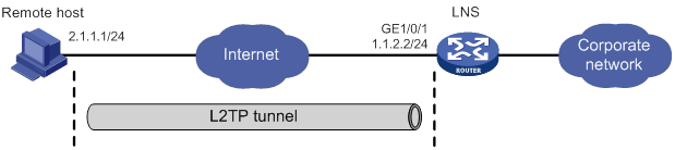
Configuration procedure
1. Configure the LNS:
# Configure IP addresses for the interfaces. (Details not shown.)
# Configure the route between the LNS and the remote host. (Details not shown.)
# Create a local user named vpdnuser, set the password, and enable the PPP service.
[LNS] local-user vpdnuser class network
[LNS-luser-network-vpdnuser] password simple Hello
[LNS-luser-network-vpdnuser] service-type ppp
[LNS-luser-network-vpdnuser] quit
# Configure local authentication for PPP users in ISP domain system.
[LNS] domain system
[LNS-isp-system] authentication ppp local
[LNS-isp-system] quit
# Enable L2TP.
[LNS] l2tp enable
# Create a PPP address pool.
[LNS] ip pool aaa 192.168.0.10 192.168.0.20
[LNS] ip pool aaa gateway 192.168.0.1
# Create Virtual-Template 1, specify its PPP authentication mode as CHAP, and use address pool aaa to assign IP addresses to the PPP users.
[LNS] interface virtual-template 1
[LNS-virtual-template1] ppp authentication-mode chap domain system
[LNS-virtual-template1] remote address pool aaa
[LNS-virtual-template1] quit
# Create L2TP group 1 in LNS mode.
[LNS] l2tp-group 1 mode lns
# Configure the local tunnel name as LNS.
[LNS-l2tp1] tunnel name LNS
# Specify Virtual-Template 1 for receiving calls.
[LNS-l2tp1] allow l2tp virtual-template 1
# Disable tunnel authentication.
[LNS-l2tp1] undo tunnel authentication
2. Configure the remote host:
# Configure the IP address of the remote host as 2.1.1.1, and configure a route to the LNS (1.1.2.2).
# Create a virtual private L2TP network connection by using the Windows system, or install the L2TP LAC client software, such as WinVPN Client.
# Complete the following configuration procedure (the procedure depends on the client software):
? Specify the PPP username as vpdnuser and the password as Hello.
? Specify the Internet interface address of the security gateway as the IP address of the LNS. In this example, the Ethernet interface for the tunnel on the LNS has an IP address of 1.1.2.2.
? Modify the connection attributes: set the protocol to L2TP, the encryption attribute to customized, and the authentication mode to CHAP.
Verifying the configuration
# On the remote host, initiate the L2TP connection. After the connection is established, the remote host can obtain the IP address 192.168.0.10 and ping the private IP address of the LNS (192.168.0.1).
# On the LNS, use the display l2tp session command to check the established L2TP session.
[LNS-l2tp1] display l2tp session
LocalSID RemoteSID LocalTID State
89 36245 10878 Established
# On the LNS, use the display l2tp tunnel command to check the established L2TP tunnel.
[LNS-l2tp1] display l2tp tunnel
LocalTID RemoteTID State Sessions RemoteAddress RemotePort RemoteName
10878 21 Established 1 2.1.1.1 1701 PC
Configuration example for LAC-auto-initiated L2TP tunnel
Network requirements
As shown in Figure 32, configure the LAC to establish an L2TP tunnel with the LNS in LAC-auto-initiated mode. When the PPP user initiates a connection, it uses the established tunnel to access the corporate network.
Configuration procedure
1. Configure the LNS:
# Configure IP addresses for the interfaces. (Details not shown.)
# Create a local user named vpdnuser, set the password, and enable the PPP service.
<LNS> system-view
[LNS] local-user vpdnuser class network
[LNS-luser-network-vpdnuser] password simple Hello
[LNS-luser-network-vpdnuser] service-type ppp
[LNS-luser-network-vpdnuser] quit
# Create Virtual-Template 1, assign an IP address to it, specify its PPP authentication mode as PAP, and assign the IP address 192.168.0.10 to the PPP user.
[LNS] interface virtual-template 1
[LNS-virtual-template1] ip address 192.168.0.1 24
[LNS-virtual-template1] ppp authentication-mode pap
[LNS-virtual-template1] remote address 192.168.0.10
[LNS-virtual-template1] quit
# Configure local authentication for PPP users in ISP domain system.
[LNS] domain system
[LNS-isp-system] authentication ppp local
[LNS-isp-system] quit
# Enable L2TP, and create L2TP group 1 in LNS mode.
[LNS] l2tp enable
[LNS] l2tp-group 1 mode lns
# Configure the local tunnel name as LNS, and specify Virtual-Template 1 for receiving tunneling requests from an LAC.
[LNS-l2tp1] tunnel name LNS
[LNS-l2tp1] allow l2tp virtual-template 1 remote LAC
# Enable tunnel authentication, and configure the authentication key as aabbcc.
[LNS-l2tp1] tunnel authentication
[LNS-l2tp1] tunnel password simple aabbcc
[LNS-l2tp1] quit
# Configure a static route so that packets destined for the PPP user will be forwarded through the L2TP tunnel.
[LNS] ip route-static 10.2.0.0 16 192.168.0.10
2. Configure the LAC:
# Configure IP addresses for the interfaces. (Details not shown.)
# Enable L2TP.
<LAC> system-view
[LAC] l2tp enable
# Create L2TP group 1 in LAC mode.
[LAC] l2tp-group 1 mode lac
# Configure the local tunnel name as LAC, and specify the IP address of the tunnel peer (LNS).
[LAC-l2tp1] tunnel name LAC
[LAC-l2tp1] lns-ip 3.3.3.2
# Enable tunnel authentication, and configure the authentication key as aabbcc.
[LAC-l2tp1] tunnel authentication
[LAC-l2tp1] tunnel password simple aabbcc
[LAC-l2tp1] quit
# Create Virtual-PPP 1. Configure its username and password as vpdnuser and Hello and PPP authentication as PAP.
[LAC] interface virtual-ppp 1
[LAC-Virtual-PPP1] ip address ppp-negotiate
[LAC-Virtual-PPP1] ppp pap local-user vpdnuser password simple Hello
[LAC-Virtual-PPP1] quit
# Configure a static route so that packets destined for the corporate network will be forwarded through the L2TP tunnel.
[LAC] ip route-static 10.1.0.0 16 virtual-ppp 1
# Trigger the LAC to establish an L2TP tunnel with the LNS.
[LAC] interface virtual-ppp 1
[LAC-Virtual-PPP1] l2tp-auto-client l2tp-group 1
3. On the remote host, configure the LAC as the gateway.
Verifying the configuration
# On the LNS, use the display l2tp session command to display the established L2TP session.
[LNS] display l2tp session
LocalSID RemoteSID LocalTID State
21409 3395 4501 Established
# On the LNS, use the display l2tp tunnel command to display the established L2TP tunnel.
[LNS] display l2tp tunnel
LocalTID RemoteTID State Sessions RemoteAddress RemotePort RemoteName
4501 524 Established 1 3.3.3.1 1701 LAC
# On the LNS, verify that you can ping 10.2.0.1, a private network address on the LAC side. This indicates that hosts on 10.2.0.0/16 and those on 10.1.0.0/16 can communicate with each other through the L2TP tunnel.
[LNS] ping -a 10.1.0.1 10.2.0.1
Ping 10.2.0.1 (10.2.0.1): 56 data bytes, press CTRL_C to break
56 bytes from 10.2.0.1: icmp_seq=0 ttl=128 time=1.000 ms
56 bytes from 10.2.0.1: icmp_seq=1 ttl=128 time=1.000 ms
56 bytes from 10.2.0.1: icmp_seq=2 ttl=128 time=1.000 ms
56 bytes from 10.2.0.1: icmp_seq=3 ttl=128 time=1.000 ms
56 bytes from 10.2.0.1: icmp_seq=4 ttl=128 time=1.000 ms
--- Ping statistics for 10.2.0.1 ---
5 packet(s) transmitted, 5 packet(s) received, 0.0% packet loss
round-trip min/avg/max/std-dev = 1.000/1.000/1.000/0.000 ms
Troubleshooting L2TP
Symptom 1: Failure to access the private network
The remote system cannot access the private network.
Analysis and solution
Possible reasons for the access failure include the following:
· Tunnel setup failure, which might occur in the following cases:
? The address of the LNS is set incorrectly on the LAC (see the lns-ip command).
? No L2TP group is configured on the LNS to receive tunneling requests from the tunnel peer (see the allow command).
? Tunnel authentication fails. Tunnel authentication must be enabled on both the LAC and LNS, and the tunnel authentication keys configured on the two sides must match.
· PPP negotiation failure, which might occur for the following reasons:
? Usernames, passwords, or both are incorrectly configured on the LAC or are not configured on the LNS.
? The LNS cannot allocate addresses. In this case, check whether IP address negotiation settings are correct on the remote system and LNS.
? The authentication type is inconsistent. For example, if the peer does not support MS-CHAP (the default authentication type for a VPN connection created on Windows 2000), the PPP negotiation will fail. In this case, change the authentication type to CHAP on Windows 2000.
Symptom 2: Data transmission failure
Data transmission fails. A connection is established, but data cannot be transmitted. For example, the LAC and LNS cannot ping each other.
Analysis and solution
Possible reasons for the data transmission failure are as follows:
· No route is available. The LAC must have a route to the private network behind the LNS, and vice versa. Otherwise, data transmission fails. You can use the display ip routing-table command on the LAC and LNS to check whether the expected routes are present. If not, configure a static route, or configure a dynamic routing protocol.
· Congestion occurs on the Internet backbone, and the packet loss ratio is high. L2TP data transmission is based on UDP, which does not provide the packet error control feature. If the line is unstable, the LAC and LNS might be unable to ping each other.
Configuring HDLC
Overview
High-level Data Link Control (HDLC) is a bit-oriented link layer protocol. HDLC can transmit any types of bit stream transparently.
HDLC supports only point-to-point link and does not support point-to-multipoint link.
HDLC supports neither IP address negotiation nor authentication. It uses keepalives to check link status.
HDLC works only on synchronous interfaces or synchronous/asynchronous interfaces in synchronous mode. HDLC is supported by serial interfaces that operate in synchronous mode and POS interfaces.
Compatibility information
Feature and hardware compatibility
This feature is supported only on Layer 2 Ethernet ports on the following modules:
· CPOS.
· CT3.
· E1.
· E1-F.
· POS.
· SAE.
· T1.
· T1-F.
Command and hardware compatibility
Commands and descriptions for centralized devices apply to the following routers:
· MSR810/810-W/810-W-DB/810-LM/810-W-LM/810-10-PoE/810-LM-HK/810-W-LM-HK/810-LMS/810-LUS.
· MSR2600-6-X1/2600-10-X1.
· MSR 2630.
· MSR3600-28/3600-51.
· MSR3600-28-SI/3600-51-SI.
· MSR3610-X1/3610-X1-DP/3610-X1-DC/3610-X1-DP-DC.
· MSR 3610/3620/3620-DP/3640/3660.
· MSR810-LM-GL/810-W-LM-GL/830-6EI-GL/830-10EI-GL/830-6HI-GL/830-10HI-GL/2600-6-X1-GL/3600-28-SI-GL.
Commands and descriptions for distributed devices apply to the following routers:
· MSR5620.
· MSR 5660.
· MSR 5680.
IPv6-related parameters are not supported on the following routers:
· MSR810/810-W/810-W-DB/810-LM/810-W-LM/810-10-PoE/810-LM-HK/810-W-LM-HK/810-LMS/810-LUS.
· MSR3600-28-SI/3600-51-SI.
Enabling HDLC encapsulation on an interface
|
Command |
Remarks |
|
|
1. Enter system view. |
system-view |
N/A |
|
2. Enter synchronous-mode serial interface view or POS interface view. |
interface interface-type interface-number |
N/A |
|
3. Enable HDLC encapsulation on the interface. |
link-protocol hdlc |
PPP encapsulation is enabled by default. |
Configuring link status polling
An HDLC-enabled interface can regularly check link status by sending keepalives to the peer at the keepalive interval at the link layer. A keepalive carries the local sender sequence number and the last received sequence number of the peer.
After sending a keepalive, an interface increments the sender sequence number by 1 in the next keepalive when the following conditions exist:
· The interface receives a response within the keepalive interval.
· The response carries the sender sequence number in the sent keepalive.
After sending a keepalive, if the interface does not receive a response within the keepalive interval, it resends the keepalive with an unchanged sequence number. When the keepalive retry limit is reached, the interface considers the link faulty and reports a link layer down event.
When you configure link status polling, follows these restrictions and guidelines:
· Link status check is disabled if you set the keepalive interval to 0.
· As a best practice, set the same keepalive interval for the two ends of a link.
· If the network has a long delay or is experiencing congestion, you can increase the keepalive interval to prevent the link from being closed.
To configure link status polling:
|
Step |
Command |
Remarks |
|
1. Enter system view. |
system-view |
N/A |
|
2. Enter interface view. |
interface interface-type interface-number |
N/A |
|
3. Set the keepalive interval. |
timer hold seconds |
By default, the keepalive interval is 10 seconds. |
|
4. Set the keepalive retry limit. |
timer-hold retry retries |
By default, the keepalive retry limit is 5. |
Displaying and maintaining HDLC
Execute display commands in any view and reset commands in user view.
|
Task |
Command |
|
Display the HDLC configuration on an interface. |
display interface serial interface-number display interface pos interface-number |
|
Clear the statistics and restart statistics collection on interfaces. |
reset counters interface [ serial [ interface-number ] ] reset counters interface [ pos [ interface-number ] ] |
HDLC configuration example
Network requirements
As shown in Figure 33, Router A and Router B are connected by POS interfaces.
Run HDLC on the link between them.
Configuration procedure
Configuring Router A
# Configure the clock mode of POS 2/2/0 as master.
<RouterA> system-view
[RouterA] interface pos 2/2/0
[RouterA-Pos2/2/0] clock master
# Enable HDLC encapsulation on POS 2/2/0.
[RouterA-Pos2/2/0] link-protocol hdlc
# Assign an IP address to POS 2/2/0.
[RouterA-Pos2/2/0] ip address 12.1.1.1 24
[RouterA-Pos2/2/0] quit
Configuring Router B
# Enable HDLC encapsulation on POS 2/2/0.
<RouterB> system-view
[RouterB] interface pos 2/2/0
[RouterB-Pos2/2/0] link-protocol hdlc
# Assign an IP address to POS 2/2/0.
[RouterB-Pos2/2/0] ip address 12.1.1.2 24
Verifying the configuration
# Ping a router from the other router, for example, ping Router B from Router A.
[RouterA] ping 12.1.1.2
Ping 12.1.1.2 (12.1.1.2): 56 data bytes, press CTRL_C to break
56 bytes from 12.1.1.2: icmp_seq=0 ttl=254 time=2.137 ms
56 bytes from 12.1.1.2: icmp_seq=1 ttl=254 time=2.051 ms
56 bytes from 12.1.1.2: icmp_seq=2 ttl=254 time=1.996 ms
56 bytes from 12.1.1.2: icmp_seq=3 ttl=254 time=1.963 ms
56 bytes from 12.1.1.2: icmp_seq=4 ttl=254 time=1.991 ms
--- Ping statistics for 12.1.1.2 ---
5 packet(s) transmitted, 5 packet(s) received, 0.0% packet loss
round-trip min/avg/max/std-dev = 1.963/2.028/2.137/0.062 ms
The output shows that Router A can successfully ping Router B.
Configuring HDLC link bundling
Overview
HDLC link bundling bundles multiple interfaces using HDLC encapsulation (also known as HDLC interfaces) together to form one logical link.
HDLC link bundling delivers the following benefits:
· Load balancing—Incoming/outgoing traffic is distributed across multiple HDLC link bundle member interfaces.
· Increased bandwidth—The bandwidth of the HDLC link bundle interface is the total bandwidth of all available member interfaces.
· Improved connection reliability—When a member interface goes down, the traffic on it automatically switches over to other available member interfaces. This avoids service interruption and improves the connection reliability of the whole HDLC link bundle.
Basic concepts
HDLC link bundle interface
An HDLC link bundle interface is a logical interface comprising a bundle of HDLC links.
HDLC link bundle
An HDLC link bundle is a group of HDLC interfaces. When you create an HDLC link bundle interface, an HDLC link bundle numbered the same as the HDLC link bundle interface is automatically generated.
Member interface
An interface assigned to an HDLC link bundle is called an HDLC link bundle member interface. Only POS interface and serial interfaces with HDLC encapsulation enabled can be assigned to an HDLC link bundle.
Member interfaces in an HDLC link bundle use the configuration on the HDLC link bundle interface to process Layer 3 services. All layer 3 service settings on the member interfaces, including the IP address, are void when the interfaces are assigned to the HDLC link bundle.
|
|
NOTE: Interfaces of different types can be assigned to an HDLC link bundle. |
States of member interfaces
An HDLC link bundle member interface can be in one of the following states:
· Initial—The member interface is down at the link layer.
· Negotiated—The member interface is as follows:
? Up at the link layer.
? Does not meet the conditions for being a Selected interface in the HDLC link bundle.
· Ready—The member interface is as follows:
? Up at the link layer.
? Meets the conditions for being a Selected interface.
? Not Selected yet due to the following restrictions:
- The maximum number of Selected interfaces.
- The minimum number of Selected interfaces required for bringing up the HDLC link bundle.
- The minimum bandwidth required for bringing up the HDLC link bundle.
· Selected—The member interface is up at the link layer, meets the conditions for being Selected, and conforms to the restrictions. Only member interfaces in Selected state can forward traffic.
If an HDLC link bundle does not contain any Selected interfaces, the HDLC link bundle interface is brought down, and it cannot forward traffic. It will not be brought up and forward traffic until Selected interfaces are detected in the HDLC link bundle. The bandwidth of an HDLC link bundle interface is the total bandwidth of all Selected interfaces.
The states of HDLC link bundle member interfaces are determined according to the following rules:
1. An interface is placed in the Initial state if its link layer protocol is down.
2. An interface is placed in the Negotiated state when its link layer protocol goes up.
3. An interface in the Negotiated state might transit to the Selected or Ready state after completing the following selection process.
4. For example:
? The number of member interfaces in the Negotiated state is M.
? The maximum number of Selected interfaces allowed in the HDLC link bundle is set to N.
The maximum number of Selected member interfaces allowed in a bundle is set by using the bundle max-active links command. If the command is not set or the set value exceeds the hardware capability, the hardware capability applies.
? When N is no smaller than M, all the member interfaces in the Negotiated state enter the Selected state.
? When N is smaller than M, these member interfaces are sorted as follows:
- They are first sorted in the descending order of rates/baud rates.
- Member interfaces with the same rate/baud rate are sorted in the descending order of bundling priorities.
- Member interfaces with the same bundling priority are sorted in the ascending order of interface numbers.
The first N member interfaces enter the Selected state, and the remaining (M-N) member interfaces enter the Ready state.
5. For example, the number of member interfaces meeting the conditions for being Selected is P. The minimum number of Selected interfaces required for bringing up the HDLC link bundle is set to Q.
The P interfaces will be Selected when any of the following conditions exist:
? P is not smaller than Q.
? The following limits are not set:
- Minimum number of Selected interfaces required for bringing up the HDLC link bundle.
- Minimum bandwidth required for bringing up the HDLC link bundle.
None of the P member interfaces will be Selected and they all stay in the Ready state when any of the following conditions exist:
? P is smaller than Q.
? The total bandwidths of the P member interfaces is smaller than the minimum bandwidth required for bringing up the HDLC link bundle.
Load balancing modes
An HDLC link bundle forwards traffic through its Selected interfaces. When multiple Selected interfaces exist in an HDLC link bundle, the device chooses the Selected interfaces to forward traffic according to its load balancing mode.
The following load balancing modes are available:
· Per-flow load balancing—Forwards packets of the same flow out of the same Selected interface. A flow is identified by match criteria.
? For IPv4 and IPv6 packets, the match criteria include source IP address and destination IP address.
? For MPLS packets, the match criteria are MPLS labels.
· Per-packet load balancing—Distributes packets evenly across all Selected interfaces by using the round-robin method.
Compatibility information
Feature and hardware compatibility
This feature is supported only on Layer 2 Ethernet ports on the following modules:
· CE3.
· CPOS.
· CT3.
· E1.
· E1-F.
· POS.
· SAE.
· T1.
· T1-F.
Command and hardware compatibility
Commands and descriptions for centralized devices apply to the following routers:
· MSR810/810-W/810-W-DB/810-LM/810-W-LM/810-10-PoE/810-LM-HK/810-W-LM-HK/810-LMS/810-LUS.
· MSR2600-6-X1/2600-10-X1.
· MSR 2630.
· MSR3600-28/3600-51.
· MSR3600-28-SI/3600-51-SI.
· MSR3610-X1/3610-X1-DP/3610-X1-DC/3610-X1-DP-DC.
· MSR 3610/3620/3620-DP/3640/3660.
· MSR810-LM-GL/810-W-LM-GL/830-6EI-GL/830-10EI-GL/830-6HI-GL/830-10HI-GL/2600-6-X1-GL/3600-28-SI-GL.
Commands and descriptions for distributed devices apply to the following routers:
· MSR5620.
· MSR 5660.
· MSR 5680.
IPv6-related parameters are not supported on the following routers:
· MSR810/810-W/810-W-DB/810-LM/810-W-LM/810-10-PoE/810-LM-HK/810-W-LM-HK/810-LMS/810-LUS.
· MSR3600-28-SI/3600-51-SI.
Configuring an HDLC link bundle interface
Configuration restrictions and guidelines
When you configure an HDLC link bundle interface, follow these restrictions and guidelines:
· The minimum number of Selected interfaces required cannot be greater than the maximum number of Selected interfaces allowed in the HDLC link bundle.
· As a best practice to guarantee correct traffic transmission, configure each of the following parameters the same at both ends of an HDLC link bundle:
? Minimum number of Selected interfaces required for bringing up the HDLC link bundle.
? Maximum number of Selected interfaces allowed in the HDLC link bundle.
? Minimum bandwidth required for bringing up the HDLC link bundle.
· After the HDLC link bundle configuration is complete, the state of each member interface is determined again if you modify any of the following parameters:
? Minimum number of Selected interfaces required for bringing up the HDLC link bundle.
? Maximum number of Selected interfaces allowed in the HDLC link bundle.
? Minimum bandwidth required for bringing up the HDLC link bundle.
· As a best practice, set the same load balancing mode at both ends of an HDLC link bundle.
Configuration procedure
|
Step |
Command |
Remarks |
|
1. Enter system view. |
system-view |
N/A |
|
2. Create an HDLC link bundle interface and enter its view. |
interface hdlc-bundle bundle-id |
By default, no HDLC link bundle interface is created. |
|
3. Set the load balancing mode. |
bundle load-balance { per-flow | per-packet } |
By default, per-packet load balancing applies. |
|
4. (Optional.) Specify a primary traffic processing slot for the interface. |
·
Distributed devices in standalone mode/centralized
devices in IRF mode: ·
Distributed devices in IRF mode: |
By default, no primary traffic processing slot is specified for an interface. Support for this command depends on the device model. For more information, see Layer 2—WAN Access Command Reference. |
|
5. (Optional.) Specify a backup traffic processing slot for the interface. |
·
Distributed devices in standalone mode/centralized
devices in IRF mode: ·
Distributed devices in IRF mode: |
By default, no backup traffic processing slot is specified for an interface. Support for this command depends on the device model. For more information, see Layer 2—WAN Access Command Reference. |
|
6. (Optional.) Set the minimum number of Selected interfaces required for bringing up the HDLC link bundle. |
bundle min-active links number |
By default, the minimum number of Selected interfaces required for bringing up an HDLC link bundle is not set. |
|
7. (Optional.) Set the maximum number of Selected interfaces allowed in the HDLC link bundle. |
bundle max-active links number |
The default setting is the maximum number of Selected interfaces supported, which varies by device model. |
|
8. (Optional.) Set the minimum bandwidth required for bringing up the HDLC link bundle. |
bundle min-active bandwidth bandwidth |
By default, the minimum bandwidth required for bringing up an HDLC link bundle is not set. |
|
9. (Optional.) Set the expected bandwidth for the HDLC link bundle interface. |
bandwidth bandwidth-value |
By default, the expected bandwidth (in kbps) is the interface baud rate divided by 1000. |
|
10. (Optional.) Set a description for the HDLC link bundle interface. |
description text |
By default, the description of an HDLC link bundle interface is the interface name followed by the Interface string. |
|
11. (Optional.) Set the MTU size for the HDLC link bundle interface. |
mtu size |
The default setting is 1500 bytes. The MTU size affects the fragmentation and reassembly of IP packets. Use this command to set a proper MTU size according to your network conditions. |
|
12. (Optional.) Restore the default settings for the HDLC link bundle interface. |
default |
N/A |
|
13. (Optional.) Bring up the HDLC link bundle interface |
undo shutdown |
By default, an HDLC link bundle interface is up. When an HDLC link bundle interface is brought up, the state of each member interface is re-determined. When an HDLC link bundle interface is shut down, the state of each Selected interface is placed into the Negotiated state. |
Assigning an interface to an HDLC link bundle
Configuration restrictions and guidelines
When you assign an interface to an HDLC link bundle, follow these restrictions and guidelines:
· POS interfaces and serial interfaces can be assigned to the same HDLC link bundle.
· An interface can belong to only one HDLC link bundle at any point in time. To assign a member interface to another HDLC link bundle, remove the interface from the current HDLC link bundle first.
· The link layer protocol of an interface to be assigned to an HDLC link bundle must be HDLC. After the interface is assigned to the HDLC link bundle, its link layer protocol cannot be changed.
· You can assign interfaces to a nonexistent HDLC link bundle as members.
· You can assign interfaces on different cards to the same HDLC link bundle.
· Changing the bundling priority of a member interface might cause the device to determine the state of each member interface.
· The peer interface directly connected to a local HDLC link bundle member interface must also join the same HDLC link bundle. A HDLC link bundle ID is locally significant. The ID on the peer device can be different from the local one.
· As a best practice, use the bundle member-priority command and the bundle max-active links command together to make sure that:
? Interconnected interfaces at both ends can be Selected.
? They can exchange traffic correctly.
Configuration procedure
|
Step |
Command |
Remarks |
|
1. Enter system view. |
system-view |
N/A |
|
2. Enter POS interface view or serial interface view. |
interface interface-type interface-number |
N/A |
|
3. Enable HDLC encapsulation on the interface. |
link-protocol hdlc |
By default, PPP encapsulation is enabled on an interface. |
|
4. Assign the interface to an HDLC link bundle. |
bundle id bundle-id |
By default, an interface is not assigned to any HDLC link bundle. |
|
5. Set the bundling priority for the member interface. |
bundle member-priority priority |
The default setting is 32768. |
Displaying and maintaining HDLC link bundling
Execute display commands in any view and reset commands in user view.
|
Task |
Command |
|
Display information about an HDLC link bundle (centralized devices in standalone mode). |
display bundle hdlc-bundle [ bundle-id ] |
|
Display information about an HDLC link bundle (distributed devices in standalone mode/centralized devices in IRF mode). |
display bundle hdlc-bundle [ bundle-id ] slot slot-number |
|
Display information about an HDLC link bundle (distributed devices in IRF mode). |
display bundle hdlc-bundle [ bundle-id ] chassis chassis-number slot slot-number |
|
Display information about an HDLC link bundle interface. |
display interface [ hdlc-bundle [ bundle-id ] ] [ brief [ description | down ] ] |
|
Clear statistics for an HDLC link bundle interface. |
reset counters interface [ hdlc-bundle [ bundle-id ] ] |
HDLC link bundling configuration example
Network requirements
As shown in Figure 34, to increase bandwidth and enhance connection reliability between Router A and Router B, create an HDLC link bundle.
Configuration procedure
Configuring Router A
# Create HDLC link bundle interface 1 and assign an IP address to it.
<RouterA> system-view
[RouterA] interface hdlc-bundle 1
[RouterA-HDLC-bundle1] ip address 1.1.1.1 24
[RouterA-HDLC-bundle1] quit
# Assign POS interfaces POS 2/2/1 to HDLC link bundle 1, and configure the interface to use the master clock mode.
[RouterA] interface pos 2/2/1
[RouterA-Pos2/2/1] clock master
[RouterA-Pos2/2/1] link-protocol hdlc
[RouterA-Pos2/2/1] bundle id 1
[RouterA-Pos2/2/1] quit
# Assign POS interfaces POS 2/2/2 to HDLC link bundle 1, and configure the interface to use the master clock mode.
[RouterA] interface pos 2/2/2
[RouterA-Pos2/2/2] clock master
[RouterA-Pos2/2/2] link-protocol hdlc
[RouterA-Pos2/2/2] bundle id 1
[RouterA-Pos2/2/2] quit
Configuring Router B
# Create HDLC link bundle interface 1 and assign an IP address to it.
<RouterB> system-view
[RouterB] interface hdlc-bundle 1
[RouterB-HDLC-bundle1] ip address 1.1.1.2 24
[RouterB-HDLC-bundle1] quit
# Assign POS interfaces POS 2/2/1 to HDLC link bundle 1.
[RouterB] interface pos 2/2/1
[RouterB-Pos2/2/1] link-protocol hdlc
[RouterB-Pos2/2/1] bundle id 1
[RouterB-Pos2/2/1] quit
# Assign POS interfaces POS 2/2/2 to HDLC link bundle 1.
[RouterB] interface pos 2/2/2
[RouterB-Pos2/2/2] link-protocol hdlc
[RouterB-Pos2/2/2] bundle id 1
[RouterB-Pos2/2/2] quit
Verifying the configuration
# Verify that the HDLC link bundle interfaces on Router A and Router B can ping each other.
[RouterA] ping –a 1.1.1.1 1.1.1.2
Ping 1.1.1.2 (1.1.1.2) from 1.1.1.1: 56 data bytes, press CTRL_C to break
56 bytes from 1.1.1.2: icmp_seq=0 ttl=255 time=0.000 ms
56 bytes from 1.1.1.2: icmp_seq=1 ttl=255 time=0.000 ms
56 bytes from 1.1.1.2: icmp_seq=2 ttl=255 time=0.000 ms
56 bytes from 1.1.1.2: icmp_seq=3 ttl=255 time=0.000 ms
56 bytes from 1.1.1.2: icmp_seq=4 ttl=255 time=0.000 ms
--- Ping statistics for 1.1.1.2 ---
5 packet(s) transmitted, 5 packet(s) received, 0.0% packet loss
round-trip min/avg/max/std-dev = 0.000/0.000/0.000/0.000 ms
# Verify that:
· POS 2/2/1 and POS 2/2/2 are in Selected state and can perform load balancing.
· The bandwidth of the HDLC link bundle is 311040 kbps, the total bandwidth of two POS interfaces.
· When one POS interface fails, the traffic can be forwarded through the other POS interface. This improves the link reliability.
Use Router A as an example.
[RouterA] display bundle hdlc-bundle 1
Bundle: HDLC-bundle1
Selected members: 2, Total bandwidth: 311040 kbps
Member State Bandwidth(kbps) Priority
Pos2/2/1 Selected 155520 32768
Pos2/2/2 Selected 155520 32768
Configuring ISDN
This feature is supported only on routers installed with BS, E1, or T1 interface modules.
Overview
Integrated Services Digital Network (ISDN) is a circuit-switched telephone network system that provides high-quality end-to-end digital connectivity at high rates over copper wire.
ISDN transmits all information in the digital form. It enables a single pair of telephone wires to transmit data and voice simultaneously at high rates. This feature enables ISDN to provide more services and higher transmission efficiency than PSTN, where information is transmitted in the analog form.
ISDN provides a set of standard multipurpose user-network interfaces (UNIs). Different services and terminals can use the same UNI interface to access an ISDN network.
ISDN interfaces
ISDN uses TDM technology to divide a physical interface into one data (D) signaling channel and multiple bearer (B) channels.
· The D-channel transmits control signaling.
· The B-channels transmit data or voice.
The ITU-T I.412 recommendation specifies the basic rate interface (BRI) and the primary rate interface (PRI).
BRI interface
The BRI interface provides two 64 kbps bearer (B) channels and one 16 kbps D-channel. This interface is also referred to as "2B + D."
The B-channels use timeslots 1 and 2 in the BRI interface.
PRI interface
The PRI interface has two variants: CE1 PRI (ITU-T recommended) and CT1 PRI (ANSI recommended). CE1 PRI provides 30 B-channels and CT1 PRI provides 23 B-channels. Different countries use different PRI variants, as shown in Table 3.
Table 3 PRI interface specifications
|
Item |
CE1 PRI (30B + D) |
CT1 PRI (23B + D) |
|
Total bandwidth |
About 2 Mbps |
About 1.5 Mbps |
|
Timeslots |
32 |
24 |
|
Timeslot assignment |
· D-channel—Timeslot 16. · B-channels—Timeslot ranges 1 to 15 and 17 to 31. NOTE: CEI PRI uses timeslot 0 for clock synchronization. |
· D-channel—Timeslot 24. · B-channels—Timeslots 1 to 23. |
|
Countries/areas |
· Most Asia countries (including China) · Europe |
· North America (including USA and Canada) · Hong Kong · Japan |
ISDN protocol stacks
ISDN provides dial-on-demand links. It sets up and maintains a link only when traffic is present.
The B-channels and the D-channel use separate protocol stacks, as shown in Table 4.
Table 4 ISDN protocol stacks and OSI reference model
|
OSI model |
ISDN layer |
D-channel |
B-channel |
|
Network layer |
Layer 3 |
Q.931, Call Control (CC) |
IP, IPX |
|
Data link layer |
Layer 2 |
Q.921 |
PPP, HDLC |
|
Physical layer |
Layer 1 |
I.430 BRI/I.431 PRI |
I.430 BRI/I.431 PRI |
The following describes the functionality of the protocols in the D-channel protocol stack:
· Q.921—Provides the following functions:
? A reliable transport for Layer 3 Q.931 signaling messages.
? Identification of frames.
? Flow control mechanisms for data transmission and reception.
· Q.931—Provides call control and management. These functions include call setup, call disconnection, and request for services from Layer 2.
· Call control (CC)—Forwards messages received by Q.931 from the network side to higher-layer applications such as the DDR or voice module for information conversion and call routing.
Figure 35 ISDN D-channel protocol stack
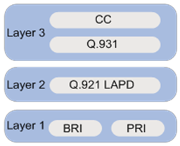
ISDN application scenarios
Figure 36 and Figure 37 show typical ISDN network diagrams for data services and voice services, respectively.
Figure 36 Data ISDN application scenario
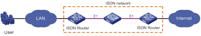
Figure 37 Voice ISDN application scenario
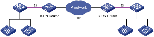
ISDN PRI configuration prerequisites
Before you can use a CE1/PRI or CT1/PRI interface to provide ISDN PRI services, you must use the pri-set command to bundle timeslots into channel sets on the interface. For each PRI set, the system creates a serial interface automatically. To configure ISDN settings for a PRI set, you must enter the view of this serial interface.
For more information about timeslot bundling, see the WAN interface part in Interface Configuration Guide.
ISDN configuration task list
This chapter describes only ISDN configurations on a BRI or PRI interface. For more information about other BRI and PRI interface configurations, see Interface Configuration Guide.
To configure ISDN PRI or BRI, perform the following tasks:
Setting the ISDN switch type on an ISDN interface
ISDN service providers in different countries implement variants of ISDN to provide varied ISDN services. When you configure an ISDN interface, you must set the switch type on the interface to be the same as the service provider switch type.
Table 5 shows the ISDN switch types available on an ISDN interface.
Table 5 ISDN switch type and ISDN interface compatibility matrix
|
Switch type |
BRI |
CT1/PRI |
CE1/PRI |
|
ANSI |
Yes |
Yes |
No |
|
AT&T |
No |
Yes |
No |
|
5ESS |
No |
Yes |
No |
|
DSS1 |
Yes |
Yes |
Yes |
|
ETSI |
Yes |
Yes |
Yes |
|
NI |
Yes |
No |
No |
|
NI2 |
No |
Yes |
No |
|
QSIG |
No |
Yes |
Yes |
|
NTT |
Yes |
Yes |
No |
|
|
NOTE: The device provides full support for DSS1. For any other variants of ISDN, the device only provides the basic call functionality. |
You cannot perform this task when a call is present on the ISDN interface.
To set the service provider switch type on an ISDN interface:
|
Step |
Command |
Remarks |
|
1. Enter system view. |
system-view |
N/A |
|
2. Enter ISDN BRI or PRI interface view. |
interface interface-type interface-number |
N/A |
|
3. Set the ISDN switch type. |
isdn protocol-type protocol |
The default is DSS1 for both BRI and PRI. To specify ANSI, AT&T, ETSI, NI, or NTT, you must make sure the interface is operating on the user side. |
Setting the ISDN functionality of an ISDN interface
An ISDN interface can provide the ISDN user-side or network-side functionality. For two ISDN devices to communicate with each other, you must configure one end as the network side and configure the other end as the user side.
When you perform this task, follow these guidelines:
· Typically, an ISDN interface is operating as the user side. However, when a BRI interface on a BSV card is connected directly to an ISDN phone, you must configure the BRI interface as the network side.
· You must configure the ISDN interface as the user side in the following situations:
? The BRI interface for data services must operate on the user side.
? ANSI, AT&T, ETSI, NI, or NTT is configured.
· You cannot perform this task when a call is present on the ISDN interface.
To set the ISDN functionality of an ISDN interface:
|
Step |
Command |
Remarks |
|
1. Enter system view. |
system-view |
N/A |
|
2. Enter ISDN BRI or PRI interface view. |
interface interface-type interface-number |
N/A |
|
3. Configure the interface as the user side or network side. |
isdn protocol-mode { network | user } |
The default is user side. |
Configuring SPID parameters for the NI switch type
NI service provider switches use service profile identifications (SPIDs) to identify services (audio, data, or speech) subscribed to by ISDN devices.
The service provider assigns one SPID for each B-channel. The device cannot place or receive calls until it sends a valid SPID when it initializes a connection to the service provider switch.
Configuring SPID assignment
SPIDs can be assigned through static manual configuration or dynamic negotiation. You must configure the SPID assignment as required by the service provider.
· If dynamic SPID negotiation is used, the service provider switch sends available SPIDs to the device. The device selects the SPID that best suits the current configuration.
· If static SPID assignment is used, you must manually configure the SPIDs assigned by the service provider on the BRI interface. When establishing a call, ISDN sends the manually assigned SPID in the ISDN Layer 3 initialization procedure without prior SPID negotiation.
By default, the device uses dynamic negotiation to obtain SPIDs.
Configuring dynamic SPID negotiation
You cannot perform this task when SPID negotiation is present on the ISDN BRI interface.
To configure dynamic SPID negotiation on a BRI interface:
|
Step |
Command |
Remarks |
|
1. Enter system view. |
system-view |
N/A |
|
2. Enter ISDN BRI interface view. |
interface bri interface-number |
N/A |
|
3. Specify a service subscribed to by the device. |
isdn spid service [ audio | data | speech ] |
By default, the device chooses the SPID that includes both speech and data services. You can repeat the command to specify multiple services. To specify all the services, execute the command without specifying any services. |
|
4. (Optional.) Initiate a SPID negotiation. |
isdn spid auto-trigger |
By default, a BRI interface initiates a SPID negotiation when it receives a call request. |
Configuring static SPID assignment
If static SPID assignment is used, you must configure a SPID for each B-channel.
When you perform this task on a BRI interface, follow these guidelines:
· Make sure the configured SPID is the same as the SPID assigned by the service provider.
· Configure a local dialing number (LDN) depending on the service provider requirement. If an LDN is configured, the setting for the isdn calling command becomes invalid.
· You cannot configure SPIDs in one of the following conditions:
? A call is present.
? A SPID negotiation is present.
To configure SPIDs on a BRI interface:
|
Step |
Command |
Remarks |
|
1. Enter system view. |
system-view |
N/A |
|
2. Enter ISDN BRI interface view. |
interface bri interface-number |
N/A |
|
3. Assign a SPID to the B1 channel. |
isdn spid1 spid [ ldn ] |
By default, no SPID or LDN is configured for the B1 channel on a BRI interface. |
|
4. Assign a SPID to the B2 channel. |
isdn spid2 spid [ ldn ] |
By default, no SPID or LDN is configured for the B2 channel on a BRI interface. |
Configuring the TSPID timer and INFORMATION retransmission
An NI-enabled BRI interface sends SPID information in Q.931 INFORMATION messages during SPID negotiation and Layer 3 initialization.
The TSPID timer sets the maximum interval that ISDN waits for a response after it sends an INFORMATION message. The timer starts when the device initiates a SPID negotiation or Layer 3 initialization.
The interface retransmits the INFORMATION message if it has not received a response from the service provider switch before the TSPID timer expires. This process continues until the interface receives a response or the maximum number of INFORMATION retransmissions is reached.
To configure the TSPID timer and the maximum number of INFORMATION retransmissions:
|
Step |
Command |
Remarks |
|
1. Enter system view. |
system-view |
N/A |
|
2. Enter ISDN BRI interface view. |
interface bri interface-number |
N/A |
|
3. Set the TSPID timer. |
isdn spid timer seconds |
The default timer value is 30 seconds. |
|
4. Set the maximum number of INFORMATION retransmissions. |
isdn spid resend times |
The default is 1. |
|
|
NOTE: You cannot perform this task when a SPID negotiation is present on the interface. |
Enabling NIT mode for NI-type switches incapable of SPID negotiation
Typically, the NI-enabled BRI interface must pass SPID negotiation or initiation before it can place a call.
You must enable Not Initial Terminal (NIT) mode on the BRI interface if the NI-type service provider switch does not support SPID negotiation.
To enable NIT mode:
|
Step |
Command |
Remarks |
|
1. Enter system view. |
system-view |
N/A |
|
2. Enter ISDN BRI interface view. |
interface bri interface-number |
N/A |
|
3. Enable NIT mode. |
isdn spid nit |
By default, NIT mode is disabled. The BRI interface performs dynamic SPID negotiation. |
Configuring Q.931 negotiation parameters
|
Step |
Command |
Remarks |
|
1. Enter system view. |
system-view |
N/A |
|
2. Enter ISDN BRI or PRI interface view. |
interface interface-type interface-number |
N/A |
|
3. Set the length of the call reference value. |
isdn crlength call-reference-length |
By default, the call reference length is 2 bytes for CE1/PRI and CT1/PRI interfaces and 1 byte for the BRI interface. The call reference identifies a call registration or cancellation request on the local interface. |
|
4. Configure the CONNECT ACK processing method. |
isdn ignore connect-ack [ incoming | outgoing ] |
By default: · After sending a CONNECT request, ISDN waits for a CONNECT ACK before it changes to the ACTIVE state for traffic transmission. · After receiving a CONNECT request, ISDN sends a CONNECT ACK and changes to the ACTIVE state. |
|
5. (Optional.) Exclude the HLC information element from the outgoing SETUP message. |
isdn ignore hlc |
By default, all ISDN protocols except 5ESS and QSIG include the HLC information element in the SETUP message. The high layer compatibility (HLC) element provides high layer compatibility check information for the called party. The called party will reject the call setup request if it detects an incompatibility. |
|
6. (Optional.) Exclude the LLC information element from the outgoing SETUP message. |
isdn ignore llc |
By default, all ISDN protocols except 5ESS and QSIG include the LLC information element in the SETUP message. The lower layer compatibility (LLC) element provides low layer compatibility check information for the called party. The called party will reject the call setup request if it detects an incompatibility. |
|
7. (Optional.) Exclude or ignore the sending complete indication for call setup. |
isdn ignore sending-complete [ incoming | outgoing ] |
By default: · The device checks incoming SETUP messages for the sending complete indication. · The device includes a sending complete indication in outgoing SETUP messages. |
|
8. Set the value of an ISDN L3 timer. |
isdn l3-timer timer-name time-interval |
The default ISDN L3 timer values vary by ISDN protocol. For the default timer values, use the display isdn parameters command. |
|
9. Set the number type and numbering plan identification for calling numbers or called numbers. |
isdn number-property number-property [ calling | called ] [ in | out ] |
By default, the system automatically selects a number type and numbering plan appropriate to the upper-layer service. |
|
10. Enable overlap sending for called numbers. |
isdn overlap-sending [ digits ] |
By default, en-bloc sending is enabled for called numbers. In the SETUP message, ISDN includes all information required by the network to process the call. If overlap sending is enabled, called number information is absent or incomplete in the outgoing SETUP message. |
|
11. Configure ISDN to include the calling-name field in outgoing packets. |
isdn carry calling-name |
By default, ISDN does not include the calling-name field in outgoing packets. |
|
12. Configure ISDN to include the connected-name field in outgoing packets. |
isdn carry connected-name |
By default, ISDN does not include the connected-name field in outgoing packets. |
|
13. Configure the ISDN interface to interpret the PROGRESS message as the ALERTING message. |
isdn progress-to-alerting enable |
By default, this function is disabled. |
|
14. Set the progress description in the progress indicator information element of ISDN signaling messages. |
isdn progress-indicator indicator |
By default, ISDN uses the progress description assigned by the upper-layer voice service. |
Configuring Q.931 call control parameters
To ensure successful call setup, make sure the call control parameters match the service provider's settings.
Configuring B-channel selection
Efficient B-channel selection for calls improves call establishment efficiency and reduces call losses on ISDN lines, especially PRI ISDN lines.
By default, ISDN interfaces on the device are operating as the user side, and they do not select B-channels for calls. B-channel selection is done by the service provider switch.
To enable an ISDN interface to select B-channels, you have the following options:
· Use the isdn bch-local-manage command to enable non-exclusive B-channel selection. The interface selects a preferred B-channel for a call, but it will use the B-channel selected by the peer end when a selection conflict occurs.
· Use the isdn bch-local-manage exclusive command to enable exclusive B-channel selection. The interface selects a preferred B-channel for a call, and it does not accept the B-channel selected by the peer end when a selection conflict occurs.
|
|
IMPORTANT: Configure exclusive B-channel selection only when the interface is the network side. If the interface is the user side, exclusive B-channel selection will cause a call establishment failure when a B-channel selection conflict occurs. |
To enable B-channel selection on an ISDN interface:
|
Step |
Command |
Remarks |
|
1. Enter system view. |
system-view |
N/A |
|
2. Enter ISDN BRI or PRI interface view. |
interface interface-type interface-number |
N/A |
|
3. Enable the interface to select B-channels for calls. |
isdn bch-local-manage [ exclusive ] |
By default, B-channel selection is disabled. The service provider switch selects B-channels for calls. |
|
4. Set a B-channel selection method. |
isdn bch-select-way { ascending | descending } |
By default, an ISDN interface selects B-channels in ascending order. This command takes effect only when the isdn bch-local-manage command is configured. |
Configuring calling number verification for incoming calls
Calling number verification enables an ISDN interface to accept calls only from a specific calling party.
Call setup will fail in one of the following conditions:
· The calling number in the incoming SETUP message is not configured on the ISDN interface.
· The incoming SETUP message does not include a calling number.
To configure calling number verification for incoming calls:
|
Step |
Command |
Remarks |
|
1. Enter system view. |
system-view |
N/A |
|
2. Enter ISDN BRI or PRI interface view. |
interface interface-type interface-number |
N/A |
|
3. Configure an accepted calling number. |
isdn caller-number caller-number |
By default, an ISDN interface accepts calls from any calling numbers. |
Configuring called-number verification for incoming calls
Called-number verification enables an ISDN interface to accept only calls placed to specific called numbers. You can configure the ISDN interface to verify only the called number or both the called number and the called subaddress. The ISDN interface will accept a call only if the called-number information matches one entry in the list of acceptable called numbers.
To configure called-number verification for incoming calls:
|
Step |
Command |
Remarks |
|
1. Enter system view. |
system-view |
N/A |
|
2. Enter ISDN BRI or PRI interface view. |
interface interface-type interface-number |
N/A |
|
3. Configure an acceptable called number. |
isdn check-called-number check-index called-party-number |
You can include a colon-separated subaddress when you specify the called number, for example, 66668888:13525. By default, ISDN does not check the called number or subaddress in incoming SETUP messages. |
Configuring ISDN calling number identification
ISDN calling number identification enables an ISDN interface to include the call number of a calling party in the outgoing call SETUP messages. The calling number information can be used for various purposes. For example, the service provider can use this information to identify the pricing scheme for the calling party. The called party can use this information to verify the origin of calls.
For the called party to receive the calling number, the connected service provider switch must support transmitting calling numbers.
As a best practice, do not configure the calling number to be sent for voice services.
To configure calling number identification:
|
Step |
Command |
Remarks |
|
1. Enter system view. |
system-view |
N/A |
|
2. Enter ISDN BRI or PRI interface view. |
interface interface-type interface-number |
N/A |
|
3. Specify a calling number. |
isdn calling calling-number |
By default, ISDN interfaces do not send a calling number in outgoing SETUP messages for any services except voice services. |
Configuring the Q.921 operating parameters
Except for the sliding window configuration, all the Q.921 operating parameter configuration tasks are available only on BRI interfaces.
To ensure successful call setup, make sure the call control parameters match the service provider's settings.
Configuring the data link type of a BRI interface
The data link type of a BRI interface can be one of the following:
· point-to-point—The BRI interface can be connected only to one terminal device.
· point-to-multipoint—The BRI interface can be connected to multiple terminal devices.
Set the data link type of a BRI interface to be the same as its connected service provider switch.
If the isdn two-tei command is configured, the data link of the BRI interface must be point-to-multipoint.
You cannot change an ISDN BRI interface's data link type when a call is present.
To configure a BRI interface's data link type:
|
Step |
Command |
Remarks |
|
1. Enter system view. |
system-view |
N/A |
|
2. Enter ISDN BRI interface view. |
interface bri interface-number |
N/A |
|
3. Set the data link type. |
·
Set the data link type to point-to-point: ·
Set the data link type to point-to-multipoint: |
The default data link type is point-to-multipoint. |
Configuring per-channel TEI assignment on a BRI interface
Terminal endpoint identifiers (TEIs) are assigned by the service provider to identify terminal devices. A TEI identifies one terminal device on a point-to-point link and identifies more than one terminal device on a point-to-multipoint link.
Typically, service provider switches assign one TEI for both B-channels on a BRI interface. If the service provider switch requires the B-channels to use different TEIs, you must configure the BRI interface to request a TEI from the switch before the interface can establish a call on a B-channel. If per-channel TEI assignment is not configured, only one B-channel can be brought up. For example, you must configure per-channel TEI assignment when a BRI interface is connected to an ISDN NI compliant DMS-100 switch in the North America.
You cannot configure per-channel TEI assignment in the following situations:
· The BRI interface's data link type is point-to-point.
· A call is present on the interface.
To configure per-channel TEI assignment on an ISDN BRI interface:
|
Step |
Command |
Remarks |
|
1. Enter system view. |
system-view |
N/A |
|
2. Enter ISDN BRI interface view. |
interface bri interface-number |
N/A |
|
3. Enable per-channel TEI assignment. |
isdn two-tei |
By default, all B-channels on a BRI interface use the same TEI. |
Configuring the leased line service for an ISDN BRI interface
You can configure two 64-kbps leased lines or one 128-kbps leased line on an ISDN BRI interface.
To configure the leased line service for an ISDN BRI interface:
|
Step |
Command |
Remarks |
|
1. Enter system view. |
system-view |
N/A |
|
2. Enter ISDN BRI interface view. |
interface bri interface-number |
N/A |
|
3. Configure the leased line service for the ISDN BRI interface. |
isdn leased-line [ B1 | B2 | 128 ] |
By default, the leased line service is not configured for an ISDN BRI interface. |
Enabling permanent Q.921 link connectivity on an ISDN BRI interface
You can enable permanent Q.921 link connectivity only on user-side ISDN BRI interfaces.
When this feature is enabled, the ISDN BRI interface establishes and maintains permanent data link connections automatically, regardless of whether or not a call is present.
When this feature is disabled, the ISDN BRI interface transits to the multiframe established state only when a call is present. In multiframe established state, the interface disconnects the Q.921 link if no Q.931 call is present when the T325 timer expires.
To ensure successful call setup when ISDN NI is used, you must enable permanent Q.921 link connectivity.
To enable permanent Q.921 link connectivity on an ISDN BRI interface:
|
Step |
Command |
Remarks |
|
1. Enter system view. |
system-view |
N/A |
|
2. Enter ISDN BRI interface view. |
interface bri interface-number |
N/A |
|
3. Enable permanent Q.921 link connectivity. |
isdn q921-permanent |
By default, permanent Q.921 link connectivity is disabled. |
Enabling persistent Layer 1 activation on a BRI interface
Persistent Layer 1 activation is available only on network-side BRI interfaces.
|
|
NOTE: Only BRI interfaces on the BSV module can operate on the network side. |
For energy efficiency, a network-side ISDN interface typically deactivates the physical layer when the data link layer connection is disconnected. To maintain physical layer connectivity when the data link connection is lost, enable persistent Layer 1 activation. This function prevents Q.921 from sending deactivation requests to the physical layer.
Persistent Layer 1 activation can only maintain the active state of the physical layer. It does not activate the physical layer if you enable it when the physical layer is inactive. In contrast, Q.921 attempts to set up data link connections if you enable permanent Q.921 link connectivity when no data link connections are present.
To enable persistent Layer 1 activation an ISDN BRI interface:
|
Step |
Command |
Remarks |
|
1. Enter system view. |
system-view |
N/A |
|
2. Enter ISDN BRI interface view. |
interface bri interface-number |
N/A |
|
3. Enable persistent Layer 1 activation. |
permanent-active |
By default, a BRI interface deactivates the physical layer when the Q.921 data link is disconnected. |
Configuring a BRI interface to supply line power
You can configure only network-side BRI interfaces to supply line power to the terminal equipment.
|
|
NOTE: Only ISDN BRI interfaces on the BSV module can operate on the network side. |
You can perform this task only when no call is present.
To enable remote powering on an ISDN BRI interface:
|
Step |
Command |
Remarks |
|
1. Enter system view. |
system-view |
N/A |
|
2. Enter ISDN BRI interface view. |
interface bri interface-number |
N/A |
|
3. Configure the interface to supply line power. |
power-source |
By default, remote powering is disabled. |
Configuring the sliding window size on an ISDN BRI interface
Q.921 sends frames in order of their sequence numbers and requires an acknowledgment of each transmitted frame. To improve transmission efficiency, Q.921 does not wait for a transmitted frame to be acknowledged before it sends the next frame. Instead, it uses a sliding window mechanism for transmission.
The sliding window mechanism enables Q.921 to send multiple continuous frames without waiting for the acknowledgment of the previous frame. The sliding window size sets the maximum number of unacknowledged frames. You can tune the size depending on the link status to maximize the throughput.
When sending a frame, Q.921 checks the number of unacknowledged frames. For example, V(A) is the sequence number of the previous acknowledged frame, V(S) is the sequence number of the frame to be sent, and k is the sliding window size. If V(A) + k = V(S), the system stops sending frames.
To configure the sliding window size on an ISDN BRI interface:
|
Step |
Command |
Remarks |
|
1. Enter system view. |
system-view |
N/A |
|
2. Enter ISDN BRI interface view. |
interface bri interface-number |
N/A |
|
3. Configure the sliding window size. |
isdn bri-slipwnd-size window-size |
The default window size is 1. |
Configuring the sliding window size on an ISDN PRI interface
Q.921 sends frames in order of their sequence numbers and requires an acknowledgment of each transmitted frame. To improve transmission efficiency, Q.921 does not wait for a transmitted frame to be acknowledged before it sends the next frame. Instead, it uses a sliding window mechanism for transmission.
The sliding window mechanism enables Q.921 to send multiple continuous frames without waiting for the acknowledgment of the previous frame. The sliding window size sets the maximum number of unacknowledged frames. You can tune the size depending on the link status to maximize the throughput.
When sending a frame, Q.921 checks the number of unacknowledged frames. Suppose V(A) is the sequence number of the previous acknowledged frame, V(S) is the sequence number of the frame to be sent, and k is the sliding window size. If V(A) + k = V(S), the system stops sending frames.
To configure the sliding window size on an ISDN PRI interface:
|
Step |
Command |
Remarks |
|
1. Enter system view. |
system-view |
N/A |
|
2. Enter ISDN PRI interface view. |
interface interface-type interface-number |
N/A |
|
3. Configure the sliding window size. |
isdn pri-slipwnd-size window-size |
The default window size is 7. |
Displaying and maintaining ISDN settings
Execute display commands in any view.
|
Task |
Command |
|
Display information about successful Q.931 calls on ISDN interfaces. |
display isdn active-channel [ interface interface-type interface-number ] |
|
Display information about calls on ISDN interfaces. |
display isdn call-info [ interface interface-type interface-number ] |
|
Display ISDN call history records. |
display isdn call-record [ interface interface-type interface-number ] |
|
Display ISDN Layer 2 and Layer 3 protocol parameters. |
display isdn parameters { protocol | interface interface-type interface-number } |
|
Display SPID information for NI-enabled BRI interfaces. |
display isdn spid [ interface interface-type interface-number ] |
ISDN configuration examples
ISDN PRI configuration example
Network requirements
As shown in Figure 38, configure an ISDN PRI line between Router A and Router B for data transmission.
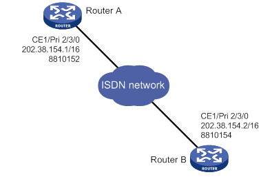
Configuration procedure
In this example, the ISDN PRI interfaces on Router A and Router B are operating as the user side (the default). You must configure the ISDN PRI interfaces as the network side on the service provider switches connected to the routers.
1. Configure Router A:
# Bundle timeslots into a PRI set on CE1/PRI interface E1 2/3/0.
<RouterA> system-view
[RouterA] controller e1 2/3/0
[RouterA-E1 2/3/0] pri-set
[RouterA-E1 2/3/0] quit
# Configure dialer access group 1 to allow any IP packets to trigger a call setup.
[RouterA] dialer-group 1 rule ip permit
# Assign Serial 2/3/0:15 an IP address.
[RouterA] interface serial 2/3/0:15
[RouterA-Serial2/3/0:15] ip address 202.38.154.1 255.255.0.0
# Enable C-DDR on the interface, configure the route to Router B, and assign the interface to dialer-group 1.
[RouterA-Serial2/3/0:15] dialer circular enable
[RouterA-Serial2/3/0:15] dialer route ip 202.38.154.2 dial-number 8810154
[RouterA-Serial2/3/0:15] dialer-group 1
2. Configure Router B:
# Bundle timeslots into a PRI set on CE1/PRI interface E1 2/3/0.
<RouterB> system-view
[RouterB] controller e1 2/3/0
[RouterB-E1 2/3/0] pri-set
[RouterB-E1 2/3/0] quit
# Create dialer access group 1 to allow any IP packets to trigger a call setup.
[RouterB] dialer-group 1 rule ip permit
# Assign Serial 2/3/0:15 an IP address.
[RouterB] interface serial 2/3/0:15
[RouterB-Serial2/3/0:15] ip address 202.38.154.2 255.255.0.0
# Enable C-DDR on the interface, configure the route to Router A, and assign the interface to dialer access group 1.
[RouterB-Serial2/3/0:15] dialer circular enable
[RouterB-Serial2/3/0:15] dialer route ip 202.38.154.1 dial-number 8810152
[RouterB-Serial2/3/0:15] dialer-group 1
# Ping 202.38.154.2 from Router A to verify that the state of a B-channel on E1 2/3/0 changes to Line up.
# Ping 202.38.154.2 again to verify that the ISDN PRI line transfers data without any losses.
NI-enabled ISDN BRI configuration example
Network requirements
As shown in Figure 39, configure an NI-enabled ISDN BRI line between Router A and Router B for data transmission.
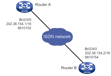
Configuration procedure
In this example, the ISDN BRI interfaces on Router A and Router B are operating on the user side (the default). You must configure the ISDN PRI interfaces as the network side on the service provider switches connected to the routers.
1. Configure Router A:
# Configure dialer-group 1 to allow any IP packets to trigger a call setup.
<RouterA> system-view
[RouterA] dialer-group 1 rule ip permit
# Assign interface BRI 2/4/0 an IP address.
[RouterA] interface bri 2/4/0
[RouterA-Bri2/4/0] ip address 202.38.154.1 255.255.0.0
# Enable C-DDR on the interface, configure the route to Router B, and assign the interface to dialer-group 1.
[RouterA-Bri2/4/0] dialer circular enable
[RouterA-Bri2/4/0] dialer route ip 202.38.154.2 dial-number 8810154
[RouterA-Bri2/4/0] dialer-group 1
# Set the switch type to NI on the BRI interface.
[RouterA-Bri2/4/0] isdn protocol-type ni
# Assign SPID 54321 to the B1 channel and SPID 65432 to the B2 channel.
[RouterA-Bri2/4/0] isdn spid1 54321
[RouterA-Bri2/4/0] isdn spid2 65432
# Set the maximum number of INFORMATION retransmissions to 2.
[RouterA-Bri2/4/0] isdn spid resend 2
2. Configure Router B:
# Configure dialer-group 1 to allow any IP packets to trigger a call setup.
<RouterB> system-view
[RouterB] dialer-group 1 rule ip permit
# Assign interface BRI 2/4/0 an IP address.
[RouterB] interface bri 2/4/0
[RouterB-Bri2/4/0] ip address 202.38.154.2 255.255.0.0
# Enable C-DDR on the interface, configure the route to Router A, and assign the interface to dialer-group 1.
[RouterB-Bri2/4/0] dialer circular enable
[RouterB-Bri2/4/0] dialer route ip 202.38.154.1 dial-number 8810152
[RouterB-Bri2/4/0] dialer-group 1
# Set the switch type to NI on the BRI interface.
[RouterB-Bri2/4/0] isdn protocol-type ni
# Assign SPID 12345 to the B1 channel and SPID 23456 to the B2 channel.
[RouterB-Bri2/4/0] isdn spid1 12345
[RouterB-Bri2/4/0] isdn spid2 23456
# Set the maximum number of INFORMATION retransmissions to 2.
[RouterB-Bri2/4/0] isdn spid resend 2
3. Verify the configuration:
# Ping 202.38.154.2 from Router A to verify that the state of a B-channel on BRI 2/4/0 changes to Line up.
# Ping 202.38.154.2 again to verify that the ISDN BRI line transfers data without any losses.
Troubleshooting
Symptom
Two devices cannot ping each other over an ISDN PRI or BRI line.
Analysis
The following are typical ISDN call failure causes:
· The ISDN interface is not configured or activated.
· The dial-up configuration is incorrect.
· The line is not well connected.
Solution
To resolve the problem:
1. Execute the display isdn call-info command to verify the interface settings:
a. If the command displays nothing, configure an ISDN interface. For more information about configuring BRI, CE1/PRI, and CT1/PRI interfaces, see Interface Configuration Guide.
b. Verify the Q.921 state of the PRI or BRI interface:
- If the PRI interface's link layer 1 is not in ISDN MULTIPLE_FRAME_ESTABLISHED state, Q.921 negotiation has failed. You must check Q.921 settings or the physical connection.
- If any link layers of the BRI interface are not in TE1_ASSIGNED state, Q.921 negotiation has failed. You must check Q.921 settings or the physical connection.
- If the Q.921 state is correct, verify the dialup configuration.
2. Verify that the physical layer is active:
a. Enable Q.921 debugging.
b. If the system displays a "Failed to send" message, execute the shutdown and undo shutdown command to re-enable the interface.
3. Verify that the dial-up configuration is correct.
4. Verify that the ISDN cables are securely connected.
5. If the problem persists, contact H3C Support.
Configuring ATM
Overview
Asynchronous Transfer Mode (ATM) is a technology based on packet transmission mode, and it also incorporates the high speed of circuit transmission mode. Due to its flexibility and support for multimedia services, ATM is regarded as a core broadband technology.
As defined by the ITU-T, data is encapsulated in cells in ATM. Each ATM cell is 53 bytes in length, of which the first 5 bytes contain cell header information and the last 48 bytes contain payload. The major function of the cell header is to identify virtual connection. In addition, it can be used to carry limited flow control, congestion control, and error control information.
ATM connections and ATM switching
ATM is connection-oriented, and ATM connections are logical (virtual) connections. In an ATM network, you can create logical connections called virtual paths (VPs) and virtual circuits (VCs) on physical links.
As shown in Figure 40, you can create multiple VPs on a physical link, and each VP can be demultiplexed into multiple VCs. Cells from different users are transmitted over different VPs and VCs, which are identified by virtual path identifier (VPI) and virtual channel identifier (VCI). ATM uses VPI/VCI pairs to identify virtual connections.
Figure 40 Physical link, VP, and VC
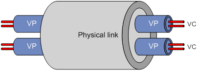
ATM interfaces support only manually created permanent virtual circuits (PVCs), not switched virtual circuits (SVCs) created through the exchange of signals. A PVC is identified by a VPI/VCI pair.
In an ATM network, an ATM switch forwards ATM cells by looking up the switching entries and changing the VPIs/VCIs. In PVC mode, the network administrator configures the switching entries and assigns VPIs/VCIs. Users can use the assigned VPIs/VCIs to configure the PVCs. If the ATM interfaces of two ATM devices are directly connected, they must be configured with the same VPIs/VCIs.
Figure 41 shows a typical ATM switching process:
1. Router A forwards a cell through PVC 0/100 on interface ATM 2/4/1.
2. ATM switch B receives the cell through PVC 0/100 on interface ATM 2/4/1.
3. ATM switch B looks up its switching entries and forwards the cell through PVC 2/101 on interface ATM 2/4/2.
4. Router C receives the cell through PVC 2/101 on interface ATM 2/4/1.
ATM architecture
ATM has a three-dimensional architecture. It contains the user plane, control plane, and management plane.
Both the user plane and the control plane are divided into the following layers: physical layer, ATM layer, ATM Adaptation Layer (AAL), and upper layer. Each layer is further divided into sublayers.
The control plane establishes and tears down connections with signaling protocols. The management plane contains layer management and plane management. Layer management manages the layers in each plane and has a layered structure corresponding to other planes. Plane management manages the system and the communications between different planes.
Figure 42 shows the relationships between layers and planes in ATM.
ATM layers have the following functions:
· Physical layer—Provides transmission channels for ATM cells. At this layer, cells received from the ATM layer are transferred into a continuous bit stream after transmission overheads are added to them. Meanwhile, continuous bit streams received from physical media are restored to cells, which are then passed to the ATM layer.
· ATM layer—Resides over the physical layer, and implements cell-based communication with its peer layer by invoking the services provided by the physical layer. It is independent of physical media, implementation of the physical layer, and types of services being carried. AAL passes 48-byte payloads, which are called segmentation and reassembly protocol data units (SAR-PDUs) to the ATM layer. The ATM layer encapsulates the 48-byte payloads in 5-byte headers, and passes 53-byte cells to the physical layer. Other functions of the ATM layer include VPI/VCI transmission, cell multiplexing/demultiplexing, and generic flow control.
· ATM Adaptation Layer—Provides interfaces between high-level protocols and the ATM Layer. It forwards information between the ATM layer and upper-layer protocols. Four types of AAL are available: AAL1, AAL2, AAL3/4, and AAL5, each of which supports specific services provided in an ATM network. H3C uses AAL5 for data communication services.
· ATM upper-layer protocols—Responsible for WAN interconnection, Layer 3 interconnection, and multiprotocol over ATM (such as IP, IPoE, PPP, and PPPoE).
ATM service types
ATM supports the following service types:
· Constant Bit Rate (CBR).
· Unspecified Bit Rate (UBR).
· Variable Bit Rate-Real Time (VBR-RT).
· Variable Bit Rate-Non Real Time (VBR-NRT).
They are used for the QoS purpose.
CBR
CBR provides ensured, constant bandwidth. The bandwidth assigned to the CBR service is decided by the Peak Cell Rate (PCR). With CBR service, a source station can send ATM cells at PCR constantly with assured QoS.
Typically, CBR is suitable for jitter-sensitive, real-time applications, such as audio and video.
VBR-RT
The VBR-RT service is provided for applications that have strict restrictions on delay and jitter, such as audio and video.
A VBR-RT connection is described by the PCR, sustainable cell rate (SCR), and maximum burst size (MBS). With the VBR-RT service, a station can send burst traffic at PCR with the maximum traffic size being MBS without cell loss and the average cell rate being SCR.
VBR-NRT
The VBR-NRT service supports non-real-time applications with burst traffic. A VBR-NRT connection is described by PCR, SCR, and MBS. The VBR-NRT service is suitable for applications sensitive to cell loss but not to delay.
UBR
The UBR service does not make any service quality commitment, guaranteeing neither cell loss ratio (CLR) nor cell delay. When traffic congestion occurs, cells of the UBR service are dropped first. The UBR service is suitable for applications with low requirements for delay and bandwidth.
ATM applications
An ATM interface can implement IPoA, IPoEoA, PPPoA, and PPPoEoA to carry data encapsulated in IP, PPP, or Ethernet across an ATM network.
IPoA
IP over ATM (IPoA) enables ATM to carry IP packets. In an IPoA implementation, ATM acts as the data link layer protocol for the IP hosts on the same network. To enable these hosts to communicate across an ATM network, IP packets must be encapsulated in ATM cells.
By making full use of the advantages of ATM, IPoA delivers excellent network performance and mature QoS assurance.
IPoEoA
IP over Ethernet over ATM (IPoEoA) uses a three-layer architecture, with IP encapsulation at the top layer, IP over Ethernet (IPoE) in the middle, and IPoEoA at the bottom.
IPoEoA is suitable where Ethernet packets are to be forwarded through ATM interfaces. In IPoEoA applications, you can associate multiple PVCs with one Layer 3 virtual Ethernet (VE) interface. PVCs associated with the same VE interface are interconnected at Layer 2.
PPPoA
PPP over ATM (PPPoA) enables ATM to carry PPP protocol packets. With PPPoA, PPP packets, in which IP packets or other protocols' packets are encapsulated, are encapsulated in ATM cells. In this implementation, ATM is the carrier of PPP packets and the communication process of PPPoA is managed by PPP, which allows for flexibility and rich applications. To transmit PPP packets across ATM, a virtual-template (VT) interface is required.
PPPoEoA
PPPoE over ATM (PPPoEoA) enables ATM to carry PPPoE protocol packets. With PPPoEoA, Ethernet packets are encapsulated in ATM cells, through which you can use a PVC to implement the functionality of Ethernet. To carry Ethernet frames over ATM, the virtual Ethernet (VE) interface was introduced. The VE interface has Ethernet characteristics and can be dynamically created. The following is the protocol stack used by the VE interface:
· ATM PVC (the bottom layer).
· Ethernet (the link layer).
· Network layer and other upper layers (the same as those for common Ethernet interfaces).
ATM OAM
OAM has the following expansions:
· Operation and Maintenance in the ITU-T I.610 recommendation (02/99).
· Operation Administration and Maintenance in LUCENT APC User Manual (03/99).
Whichever expansion is used, OAM provides a way of detecting faults, isolating faults, and monitoring network performance without interrupting ongoing services. By inserting OAM cells, which are constructed in the standard ATM cell format, in cell streams, you can obtain specific information about the network.
ATM OAM provides the following functions:
· OAM Alarm Indication Signal/Remote Defect Indication—The PVC goes down when specific number of successive AIS/RDI alarm cells are received. The PVC comes up when no AIS/RDI alarm cells are received within the specified time.
· OAM Continuity Check—OAM CC requires that one end of the PVC must be configured as the CC cell source and the other end as the CC cell sink. If the detecting end fails to receive CC cells within 3 seconds, the state of the PVC changes to down. The PVC comes up only after CC cells are received again.
· OAM F5 Loopback—Sends OAM F5 Loopback cells at the specified interval after you enable OAM F5 Loopback transmission and retransmission detection and specify related parameters. If the sender fails to receive a response cell within the specified interval, it sends an OAM F5 Loopback cell again. The state of the PVC is updated during the Loopback detection. The PVC comes up when the specified number of successive OAM F5 Loopback cells are received. The PVC goes down when the specified number of successive OAM F5 Loopback cells are not received.
· OAM F5 end-to-end—Sends OAM F5 end-to-end cells through the specified PVC on the specified ATM interface. If no response is received within the specified period, the link might be disconnected or congested.
Feature and hardware compatibility
ATM is supported only by MSR routers installed with an ATM-OC3, ADSL2+, G.SHDSL, or G.SHDSL.BIS interface module.
ATM is not supported on the MSR2600-6-X1-GL/3600-28-SI-GL/3600-28-SI/3600-51-SI routers.
ATM configuration task list
|
Tasks at a glance |
Remarks |
|
(Required.) Configuring an ATM interface |
N/A |
|
(Required.) Configuring a PVC |
N/A |
|
(Optional.) Configuring a PVC group |
N/A |
|
(Required.) Configuring the ATM AAL5 encapsulation type |
N/A |
|
(Required.) Configuring the ATM service type |
N/A |
|
Configuring applications carried by ATM: · (Optional.) Configuring a VE interface · (Required.) Perform one of the following tasks: |
When you configure IPoEoA or PPPoEoA, you must configure VE interfaces. |
|
(Optional.) Configuring VP policing |
N/A |
|
(Optional.) Re-marking the CLP flag value of ATM cells |
N/A |
|
(Optional.) Configuring ATM OAM functions |
N/A |
Configuring an ATM interface
Depending on the actual networking environment and system requirements, you might be required to modify certain parameters of ATM interfaces and subinterfaces. For more information about ATM interface configuration, see Interface Configuration Guide.
Configuring a PVC
In PVC mode, the network administrator configures the switching entries and assigns VPI/VCI values. You can configure the PVCs by using the assigned VPI/VCI values. If the ATM interfaces of two ATM devices are directly connected, you must configure the same VPI/VCI values for the interfaces.
To configure a PVC:
|
Step |
Command |
Remarks |
|
1. Enter system view. |
system-view |
N/A |
|
2. Enter ATM interface view or ATM subinterface view. |
interface atm { interface-number | interface-number.subnumber } |
N/A |
|
3. Create a PVC and enter PVC view. |
pvc { pvc-name [ vpi/vci ] | vpi/vci } |
By default, no PVCs exist. |
|
4. Bring up the PVC. |
undo shutdown |
By default, the PVC is up. |
Configuring a PVC group
A PVC group can share traffic load among PVCs in it by transmitting IP packets of different priorities through different PVCs.
You can configure the priority of IP packets carried by each PVC. IP packets are transmitted through the PVC corresponding to the priority of the IP packets.
· If no corresponding PVC is found, the IP packets are transmitted through the default PVC.
· If no default PVC is configured, the IP packets are distributed across the PVCs that are not configured with priorities on a per-packet basis.
· If all PVCs are configured with priorities, the IP packets are dropped.
Data packets that are not IP packets are distributed across all PVCs in the PVC group on a per-packet basis.
All PVCs in a PVC group obtain the encapsulation type and protocol type from the PVC group.
To configure a PVC group:
|
Step |
Command |
Remarks |
|
1. Enter system view. |
system-view |
N/A |
|
2. Enter ATM interface view or ATM subinterface view. |
interface atm { interface-number | interface-number.subnumber } |
N/A |
|
3. Create a PVC group and enter PVC group view. |
pvc-group group-number |
By default, no PVC groups exist. |
|
4. Create a PVC and enter PVC view. |
pvc { pvc-name [ vpi/vci ] | vpi/vci } |
By default, no PVCs exist. |
|
5. Configure priority of IP packets carried by the PVC. |
precedence { min-number [ to max-number ] | default } |
By default, no priority is configured. |
|
6. Bring up the PVC. |
undo shutdown |
By default, the PVC is up. |
Configuring the ATM AAL5 encapsulation type
ATM AAL5 encapsulation includes the following types:
· aal5snap—Logical Link Control (LLC)/Subnet Access Protocol (SNAP) encapsulation.
· aal5mux—MUX multiplexing encapsulation.
· aal5nlpid—RFC 1490 encapsulation.
Different encapsulations use different formats and support different mappings.
· aal5snap—Supports IPoA, IPoEoA, PPPoA, and PPPoEoA mappings.
· aal5mux—Supports IPoA, IPoEoA, PPPoA, and PPPoEoA mappings, but can only support one protocol at a time.
· aal5nlpid—Supports only IPoA mappings.
Follow these guidelines when you configure ATM AAL5 encapsulation types:
· Devices on the two ends must be configured with the same ATM AAL5 encapsulation types.
· Only aal5snap supports InARP. You cannot configure InARP when aal5mux or aal5nlpid is used.
· Although a PVC or PVC group can carry multiple protocols, a specific encapsulation type might not support some of the applications (such as IPoA, IPoEoA, PPPoA, and PPPoEoA). In such cases, the system displays error prompts.
· When you change the encapsulation type for a PVC or PVC group, and the mappings that you have configured conflict with the new encapsulation type, the PVC or PVC group deletes the configurations of all conflicting mappings.
To configure the ATM AAL5 encapsulation type:
|
Step |
Command |
Remarks |
|
1. Enter system view. |
system-view |
N/A |
|
2. Enter ATM interface view or ATM subinterface view. |
interface atm { interface-number | interface-number.subnumber } |
N/A |
|
3. Enter PVC view or PVC group view. |
·
Enter PVC view: ·
Enter PVC group view: |
N/A |
|
4. Configure the ATM AAL5 encapsulation type. |
encapsulation { aal5mux | aal5nlpid | aal5snap } |
The default encapsulation type is aal5snap. |
Configuring the ATM service type
ATM supports the following service types: CBR, UBR, VBR-RT, and VBR-NRT. You can configure service types for PVCs, and configure different transmission priorities for PVCs associated with the UBR, VBR-NRT, and VBR-RT services. A greater value represents a higher priority. PVCs with higher priorities occupy more bandwidths. PVCs with the same priority occupy the same bandwidths. You cannot configure transmission priorities for CBR services.
To configure the ATM service type:
|
Step |
Command |
Remarks |
|
1. Enter system view. |
system-view |
N/A |
|
2. Enter ATM interface view or ATM subinterface view. |
interface atm { interface-number | interface-number.subnumber } |
N/A |
|
3. Enter PVC view or PVC view in PVC group. |
·
Enter PVC view: · Enter PVC view in a PVC group: a. pvc-group group-number b. pvc { pvc-name [ vpi/vci ] | vpi/vci } |
N/A |
|
4. Configure the service type and related parameters for the PVC. |
·
Set the service type to CBR and configure
related parameters: ·
Set the service type to UBR and
configure related parameters: ·
Set the service type to VBR-NRT and
configure related parameters: ·
Set the service type to VBR-RT and configure
related parameters: |
The default service type is UBR. The newly configured service type overwrites the existing ones. Different PVCs in a PVC group or interface can be configured with different service types. |
|
5. Configure the transmission priority for the PVC. |
transmit-priority priority |
By default, the transmission priority is: · 0 for UBR services. · 5 for VBR-NRT services. · 8 for VBR-RT services. When you change the service type for the PVC, the transmission priority of the PVC is restored to the default. |
Configuring applications carried by ATM
As shown in Table 6, although ATM can carry multiple protocols, a specific encapsulation type might not support ATM applications (such as IPoA, IPoEoA, PPPoA, and PPPoEoA).
Table 6 Encapsulation type support for ATM applications
|
ATM application |
aal5snap |
aal5mux |
aal5nlpid |
|
IPoA |
Supported |
Supported (InARPoA not supported) |
Supported (InARPoA not supported) |
|
IPoEoA |
Supported |
Supported |
Not supported |
|
PPPoA |
Supported |
Supported |
Not supported |
|
PPPoEoA |
Supported |
Supported |
Not supported |
|
|
NOTE: When aal5snap is used, a PVC or PVC group can carry two or more protocols at the same time. When aal5mux is used, a PVC or PVC group supports only one protocol at a time. |
Configuring a VE interface
Before you configure IPoEoA and PPPoEoA, you must specify a VE interface.
To configure a VE interface:
|
Step |
Command |
Remarks |
|
1. Enter system view. |
system-view |
N/A |
|
2. Create a VE interface and enter VE interface view. |
interface virtual-ethernet interface-number |
If the interface already exists, use this command to enter the VE interface view. You can create a maximum of 1024 VE interfaces. |
|
3. Configure the description for the interface. |
description text |
By default, the description is in the format of interface-name Interface, for example, Virtual-Ethernet 0 Interface. |
|
4. Configure the MTU for the interface. |
mtu size |
By default, the MTU for the interface is 1500 bytes. |
|
5. Configure the MAC address for the interface. |
mac-address mac-address |
By default, the VE interface uses the bridge MAC address as its MAC address. |
|
6. Configure the expected bandwidth for the interface. |
bandwidth bandwidth-value |
By default, the expected bandwidth (in kbps) is the interface baud rate divided by 1000. |
|
7. Restore the default settings for the interface. |
default |
N/A |
|
shutdown |
By default, the interface is up. |
To configure a VE subinterface:
|
Step |
Command |
Remarks |
|
1. Enter system view. |
system-view |
N/A |
|
2. Create a VE subinterface and enter VE subinterface view. |
interface virtual-ethernet interface-number.subnumber |
By default, no VE subinterfaces exist. |
|
3. Configure the description for the subinterface. |
description text |
By default, the description is in the format of interface-name Interface. |
|
4. Configure the MTU for the subinterface. |
mtu size |
By default, the MTU for the subinterface is 1500 bytes. |
|
5. Configure the expected bandwidth for the subinterface. |
bandwidth bandwidth-value |
By default, the expected bandwidth (in kbps) is the subinterface baud rate divided by 1000. |
|
6. Restore the default settings for the interface. |
default |
N/A |
|
7. Shut down the subinterface. |
shutdown |
By default, the subinterface is up. |
Configuring IPoA
To enable the upper-layer protocols to find a remote device by its IP address, map the IP address of the remote device to the local PVC or PVC group.
To configure an IP mapping, use one of the following methods:
· Static IP address mapping—Maps the IP address of the remote interface to the PVC or PVC group.
· Default mapping—If a packet cannot find the mapping for the next hop address, the packet is transmitted through the PVC or PVC group configured with the default mapping.
· InARP mapping—Uses Inverse Address Resolution Protocol (InARP) to resolve the IP address of the remote interface that is connected to the local PVC or PVC group. You do not need to configure a static IP address for the PVC or PVC group. Figure 43 shows the InARP working process. The IP addresses are the IP addresses of the ATM interfaces to which the PVC or PVC group belongs.
Figure 43 InARP working process
Follow these guidelines when you configure IPoA:
· All encapsulation types support IPoA mapping, but only aal5snap supports InARP mapping. You cannot configure InARP mapping when aal5mux or aal5nlpid is used.
· Multiple IP addresses can be mapped to the same PVC or PVC group. You can configure static IP mapping, default mapping, and InARP mapping at the same time. Different PVCs or PVC groups on the same interface cannot be mapped to the same IP address. The PVCs or PVC groups on the same interface can be configured with only one default mapping.
· If the interfaces of two routers are connected back-to-back, the local PVC mapped to the remote IP address must have the same VPI/VCI value as the remote PVC mapped to the local IP address.
To configure IPoA:
|
Step |
Command |
Remarks |
|
1. Enter system view. |
system-view |
N/A |
|
2. Enter ATM interface view or ATM subinterface view. |
interface atm { interface-number | interface-number.subnumber } |
N/A |
|
3. Enter PVC view or PVC group view. |
·
Enter PVC view: ·
Enter PVC group view: |
N/A |
|
4. Configure an IPoA mapping to enable the PVC or PVC group to carry IP packets. |
map ip { ip-address | default | inarp [ minutes ] } |
By default, no mappings exist. |
|
5. (Optional.) Enable the broadcast attribute for the PVC or PVC group. |
broadcast |
By default, the broadcast attribute is disabled. On an ATM interface, multicast or broadcast packets are sent through all PVCs or PVC groups that have the broadcast attribute enabled. You must configure this command on a PVC or PVC group where broadcast or multicast packets must be sent. |
Configuring IPoEoA
Follow these guidelines when you configure IPoEoA:
· In an IPoEoA application, configure the IP address for VE interfaces instead of ATM interfaces. The IP address configuration does not take effect on ATM interfaces.
· In an IPoEoA application, configure Class Based Queuing (CBQ) on PVCs or PVC groups.
Perform this task to enable a PVC or PVC group to carry Ethernet packets.
To configure IPoEoA:
|
Step |
Command |
Remarks |
|
1. Enter system view. |
system-view |
N/A |
|
2. Create a VE interface. |
interface virtual-ethernet interface-number |
N/A |
|
3. Return to system view. |
quit |
N/A |
|
4. Enter ATM interface view or ATM subinterface view. |
interface atm { interface-number | interface-number.subnumber } |
N/A |
|
5. Enter PVC view or PVC group view. |
·
Enter PVC view: ·
Enter PVC group view: |
N/A |
|
6. Configure an IPoEoA mapping. |
map bridge virtual-ethernet interface-number |
By default, no mappings exist. This command references the VE interface previously created. |
Configuring PPPoA
When two routers are connected by using DSL interfaces through a dial-up connection, configure them as a PPPoA server and client. The PPPoA server acts as the PPP server, and you must configure an address pool for it to assign an IP address to the remote node. The PPPoA client acts as the PPP client, and you must configure address negotiation on it to accept the IP address assigned by the server end. For more information, see "Configuring PPP and MP."
Perform this task to enable a PVC or PVC group to carry PPP and configure a PPP mapping for the PVC or PVC group.
To configure PPPoA:
|
Step |
Command |
Remarks |
|
1. Enter system view. |
system-view |
N/A |
|
2. Create a VT interface. |
interface virtual-template vt-number |
N/A |
|
3. Configure PPP authentication and IP address. For the PPP server, configure an address pool to assign an IP address to the remote node. For the PPP client, configure address negotiation to accept the IP address assigned by the server end. |
For more information, see "Configuring PPP and MP." |
Configure PPP authentication and IP address on the VT interface instead of an ATM interface. The IP address configuration does not take effect on ATM interfaces. When you configure a static route for the VT interface, specify the next hop instead of the output interface. If you have to specify an output interface, make sure the physical interface bound to the VT is valid to ensure correct packet transmission. |
|
4. Return to system view. |
quit |
N/A |
|
5. Enter ATM interface view or ATM subinterface view. |
interface atm { interface-number | interface-number.subnumber } |
N/A |
|
6. Enter PVC view or PVC group view. |
·
Enter PVC view: ·
Enter PVC group view: |
N/A |
|
7. Configure a PPPoA mapping. |
map ppp virtual-template vt-number |
By default, no mappings exist. |
Configuring PPPoEoA
PPPoE uses the Client/Server model. It encapsulates PPP packets into Ethernet frames and provides point-to-point connection on Ethernet. Perform this task to enable a PVC or PVC group to carry PPPoE and configure a PPPoE mapping for the PVC or PVC group.
To configure PPPoEoA:
|
Step |
Command |
Remarks |
|
1. Enter system view. |
system-view |
N/A |
|
2. Create a VT interface. |
interface virtual-template vt-number |
N/A |
|
3. Configure PPP authentication and IP address. For the PPP server, configure an address pool to assign an IP address to the remote node. For the PPP client, configure address negotiation to accept the IP address assigned by the server end. |
For more information, see "Configuring PPP and MP." |
Configure PPP authentication and IP address on the VT interface instead of an ATM interface. The IP address configuration does not take effect on ATM interfaces. When you configure a static route for the VT interface, specify the next hop instead of the output interface. If you have to specify an output interface, make sure the physical interface bound to the VT is valid to ensure correct packet transmission. |
|
4. Return to system view. |
quit |
N/A |
|
5. Create a VE interface. |
interface virtual-ethernet interface-number |
N/A |
|
6. Configure PPPoE parameters on the VE interface. Bind the PPPoE server to a VT interface, and bind the PPPoE client to a Dialer interface for dial-in access. |
For more information, see "Configuring PPPoE." |
N/A |
|
7. Return to system view. |
quit |
N/A |
|
8. Enter ATM interface view or ATM subinterface view. |
interface atm { interface-number | interface-number.subnumber } |
N/A |
|
9. Enter PVC view or PVC group view. |
·
Enter PVC view: ·
Enter PVC group view: |
N/A |
|
10. Configure a PPPoEoA mapping. |
map bridge virtual-ethernet interface-number |
By default, no mappings exist. This command references the VE interface previously created. |
Configuring VP policing
A VP is the collection of all PVCs with the same VPI value. VP policing is used to manage the maximum bandwidth of the VP, and monitor the traffic of the inbound and outbound directions of the VP on a physical interface. When the maximum transmission rate of the VP exceeds the specified value, the exceeded flows are dropped. When VP policing is applied, the parameters of PVC are still valid. Packets can be transmitted or received only when the parameters of PVC and VP policing are met. In calculating the traffic, the LLC/SNAP, MUX, and NLPID headers are included, but the ATM cell header is not included.
To configure VP policing:
|
Step |
Command |
Remarks |
|
1. Enter system view. |
system-view |
N/A |
|
2. Enter ATM interface view. |
interface atm interface-number |
N/A |
|
3. Configure parameters for VP policing. |
vp limit vpi scr |
By default, VP policing is disabled. |
Re-marking the CLP flag value of ATM cells
You can re-mark the cell loss priority (CLP) flag value of ATM cells to specify the drop precedence for the cells.
To re-mark the CLP flag value of ATM cells:
|
Step |
Command |
Remarks |
|
1. Enter system view. |
system-view |
N/A |
|
2. Create a traffic class and enter its view. |
traffic classifier classifier-name [ operator { and | or } ] |
N/A |
|
3. Configure match criteria. |
if-match [ not ] match-criteria |
By default, no match criteria exist. |
|
4. Return to system view. |
quit |
N/A |
|
5. Create a traffic behavior and enter its view. |
traffic behavior behavior-name |
By default, no traffic behaviors exist. |
|
6. Re-mark the CLP flag value of ATM cells. |
remark [ green | red | yellow ] atm-clp atm-clp-value |
By default, the CLP flag value of ATM cells is not re-marked. The CLP flag value of ATM cells is 0 or 1. The cells with a CLP flag value of 1 are dropped first when network congestion occurs. |
|
7. Return to system view. |
quit |
N/A |
|
8. Create a QoS policy and enter its view. |
qos policy policy-name |
N/A |
|
9. Associate a traffic class with a traffic behavior in the QoS policy. |
classifier classifier-name behavior behavior-name [ mode dcbx ] |
By default, a traffic class is not associated with a traffic behavior. |
|
10. Return to system view. |
quit |
N/A |
|
11. Enter ATM interface view or ATM subinterface view. |
interface atm { interface-number | interface-number.subnumber } |
N/A |
|
12. Enter PVC view or PVC view in PVC group. |
·
Enter PVC view: · Enter PVC view in PVC group: a. pvc-group group-number b. pvc { pvc-name [ vpi/vci ] | vpi/vci } |
N/A |
|
13. Apply the QoS policy to the PVC. |
qos apply policy policy-name outbound |
By default, no QoS policy is applied to the PVC. |
|
|
NOTE: For more information about traffic class, traffic behavior, and QoS policy, see ACL and QoS Configuration Guide. |
Configuring ATM OAM functions
|
Step |
Command |
Remarks |
|
1. Enter system view. |
system-view |
N/A |
|
2. Enter ATM interface view or ATM subinterface view. |
interface atm { interface-number | interface-number.subnumber } |
N/A |
|
3. Enter PVC view or PVC view in PVC group. |
·
Enter PVC view: · Enter PVC view in PVC group: a. pvc-group group-number b. pvc { pvc-name [ vpi/vci ] | vpi/vci } |
N/A |
|
4. Enable OAM F5 Loopback transmission and retransmission detection. |
oam loopback interval [ up up-count down down-count retry retries ] |
By default, OAM F5 Loopback cell transmission is disabled. Responses are sent if an OAM F5 Loopback cell is received. |
|
5. Configure related parameters for AIS/RDI alarm cell detection. |
oam ais-rdi up up-seconds down down-seconds |
By default, the PVC goes down when the system receives successive AIS/RDI alarm cells in one second. The PVC comes up when the system does not receive any AIS/RDI alarm cells in 3 seconds. |
|
6. Send OAM F5 end-to-end cells to check the link connection. |
oam ping interface atm { interface-number | interface-number.subnumber } pvc { pvc-name | vpi/vci } [ number timeout ] |
Available in any view. |
Displaying and maintaining ATM
Execute display commands in any view and reset commands in user view.
|
Task |
Command |
|
Display PVC information. |
display atm pvc-info [ interface interface-type { interface-number | interface-number.subnumber } [ pvc { pvc-name | vpi/vci } ] ] |
|
Display PVC group information. |
display atm pvc-group [ interface interface-type { interface-number | interface-number.subnumber } [ pvc-group group-number ] ] |
|
Display mapping information about PVCs or PVC groups. |
display atm map-info [ interface interface-type { interface-number | interface-number.subnumber } [ pvc { pvc-name | vpi/vci } | pvc-group group-number ] ] |
|
Display VE interface information. |
display interface [ virtual-ethernet [ interface-number ] ] [ brief [ description | down ] ] |
|
Clear PVC statistics. |
reset atm interface [ interface-type { interface-number | interface-number.subnumber } ] |
|
Clear VE interface statistics. |
reset counters interface [ virtual-ethernet [ interface-number | interface-number.subnumber ] ] |
ATM configuration examples
IPoA configuration example
Network requirements
As shown in Figure 44, Router A, B, and C are connected to the ATM network for intercommunication.
The IP addresses of the ATM interfaces of the three routers are 202.38.160.1/24, 202.38.160.2/24, and 202.38.160.3/24.
In the ATM network:
· The VPIs/VCIs of Router A are 0/40 and 0/41, connected to Router B and Router C, respectively.
· The VPIs/VCs of Router B are 0/50 and 0/51, connected to Router A and Router C, respectively.
· The VPIs/VCIs of Router C are 0/60 and 0/61, connected to Router A and Router B, respectively.
All the PVCs on ATM interfaces of the three routers operate in IPoA application mode.
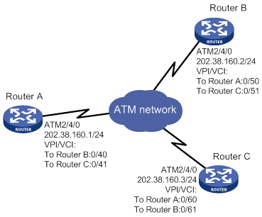
Configuration procedure
1. Configure Router A:
# Enter the view of interface ATM 2/4/0 and configure an IP address for it.
<RouterA> system-view
[RouterA] interface atm 2/4/0
[RouterA-ATM2/4/0] ip address 202.38.160.1 255.255.255.0
# Create PVCs, and enable them to carry IP.
[RouterA-ATM2/4/0] pvc to_b 0/40
[RouterA-ATM2/4/0-pvc-to_b-0/40] map ip 202.38.160.2
[RouterA-ATM2/4/0-pvc-to_b-0/40] quit
[RouterA-ATM2/4/0] pvc to_c 0/41
[RouterA-ATM2/4/0-pvc-to_c-0/41] map ip 202.38.160.3
2. Configure Router B:
# Enter the view of interface ATM 2/4/0 and configure an IP address for it.
<RouterB> system-view
[RouterB] interface atm 2/4/0
[RouterB-ATM2/4/0] ip address 202.38.160.2 255.255.255.0
# Create PVCs, and enable them to carry IP.
[RouterB-ATM2/4/0] pvc to_a 0/50
[RouterB-ATM2/4/0-pvc-to_a-0/50] map ip 202.38.160.1
[RouterB-ATM2/4/0-pvc-to_a-0/50] quit
[RouterB-ATM2/4/0] pvc to_c 0/51
[RouterB-ATM2/4/0-pvc-to_c-0/51] map ip 202.38.160.3
3. Configure Router C:
# Enter the view of interface ATM 2/4/0 and configure an IP address for it.
<RouterC> system-view
[RouterC] interface atm 2/4/0
[RouterC-ATM2/4/0] ip address 202.38.160.3 255.255.255.0
# Create PVCs, and enable them to carry IP.
[RouterC-ATM2/4/0] pvc to_a 0/60
[RouterC-ATM2/4/0-pvc-to_a-0/60] map ip 202.38.160.1
[RouterC-ATM2/4/0-pvc-to_a-0/60] quit
[RouterC-ATM2/4/0] pvc to_b 0/61
[RouterC-ATM2/4/0-pvc-to_b-0/61] map ip 202.38.160.2
Verifying the configuration
# Use the ping command to verify that the three routers can ping each other successfully. (Details not shown.)
IPoEoA configuration example
Network requirements
As shown in Figure 45, the hosts in the two Ethernets are connected to the ATM network through ADSL Router A and ADSL Router B. They communicate with Router C through DSLAM.
The IP address of the VE interface of Router C is 202.38.160.1.
The VPI/VCI values of the two PVCs connecting Router C and DSLAM are 0/60 and 0/61, pointing to Router A and Router B, respectively.
Both the WAN port of Router C and the DSL interfaces of the ADSL routers use IPoEoA.
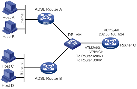
Configuration procedure
1. Configure Router C:
# Create a VE interface and configure an IP address for it.
<RouterC> system-view
[RouterC] interface virtual-ethernet 2/4/0
[RouterC-Virtual-Ethernet2/4/0] ip address 202.38.160.1 255.255.255.0
[RouterC-Virtual-Ethernet2/4/0] quit
# Create PVCs, and enable them to carry IPoE.
[RouterC] interface atm 2/4/0.1
[RouterC-ATM2/4/0.1] pvc to_adsl_a 0/60
[RouterC-ATM2/4/0.1-pvc-to_adsl_a-0/60] map bridge virtual-ethernet 2/4/0
[RouterC-ATM2/4/0.1-pvc-to_adsl_a-0/60] quit
[RouterC-ATM2/4/0.1] pvc to_adsl_b 0/61
[RouterC-ATM2/4/0.1-pvc-to_adsl_b-0/61] map bridge virtual-ethernet 2/4/0
2. Configure ADSL Router A:
# Create a VE interface and configure an IP address for it.
<RouterA> system-view
[RouterA] interface virtual-ethernet 2/4/1
[RouterA-Virtual-Ethernet2/4/1] ip address 202.38.160.2 255.255.255.0
[RouterA-Virtual-Ethernet2/4/1] quit
# Create a PVC and enable it to carry IPoE.
[RouterA] interface atm 2/4/0.1
[RouterA-ATM2/4/0.1] pvc to_c 0/60
[RouterA-ATM2/4/0.1-pvc-to_c-0/60] map bridge virtual-ethernet 2/4/1
3. Configure ADSL Router B in the same way ADSL Router A is configured.
Verifying the configuration
# Use the ping command to verify that both ADSL Router A and ADSL Router B can ping Router C successfully. (Details not shown.)
PPPoA configuration example
Network requirements
As shown in Figure 46, two hosts dial into the ATM network each through an ADSL router, and communicate with Router C through DSLAM. This configuration example has the following requirements:
· Create VT for multiuser on Router C, and configure PPP mapping on VT.
· The VPI/VCI values of two PVCs connecting Router C and DSLAM are 0/60 and 0/61, pointing to ADSL Router A and ADSL Router B, respectively.
· Both the WAN port of Router C and the DSL interfaces of the two ADSL routers use PPPoA. PPP authentication is not performed. The IP addresses of the two ADSL routers are assigned by Router C.
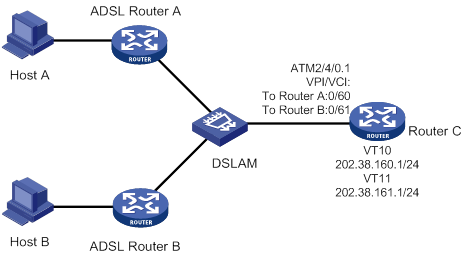
Configuration procedure
1. Configure Router C (PPPoA server):
# Create VT interfaces and configure IP addresses for them. Assign IP addresses to the remote ends.
<RouterC> system-view
[RouterC] interface virtual-template 10
[RouterC-Virtual-Template10] ip address 202.38.160.1 255.255.255.0
[RouterC-Virtual-Template10] remote address 202.38.162.1
[RouterC-Virtual-Template10] quit
[RouterC] interface virtual-template 11
[RouterC-Virtual-Template11] ip address 202.38.161.1 255.255.255.0
[RouterC-Virtual-Template11] remote address 202.38.162.2
[RouterC-Virtual-Template11] quit
# Create PVCs, and enable them to carry PPP.
[RouterC] interface atm 2/4/0.1
[RouterC-ATM2/4/0.1] pvc to_adsl_a 0/60
[RouterC-ATM2/4/0.1-pvc-to_adsl_a-0/60] map ppp virtual-template 10
[RouterC-ATM2/4/0.1-pvc-to_adsl_a-0/60] quit
[RouterC-ATM2/4/0.1] pvc to_adsl_b 0/61
[RouterC-ATM2/4/0.1-pvc-to_adsl_b-0/61] map ppp virtual-template 11
2. Configure ADSL Router A (PPPoA client):
# Create a VT interface, and enable IP address negotiation.
<RouterA> system-view
[RouterA] interface virtual-template 0
[RouterA-Virtual-Template0] ip address ppp-negotiate
[RouterA-Virtual-Template0] quit
# Create a PVC, and enable it to carry PPP.
[RouterA] interface atm 2/4/0
[RouterA-ATM2/4/0] pvc pppoa 0/60
[RouterA-ATM2/4/0-pvc-pppoa-0/60] map ppp virtual-template 0
[RouterA-ATM2/4/0-pvc-pppoa-0/60] quit
[RouterA-ATM2/4/0] quit
3. Configure ADSL Router B in the same way ADSL Router A is configured.
Verifying the configuration
Both ADSL Router A and ADSL Router B can ping Router C successfully.
PPPoEoA configuration example
Network requirements
As shown in Figure 47, the hosts in the two Ethernets are connected to the ATM network through ADSL Router A and ADSL Router B. They communicate with Router C through DSLAM.
The IP addresses of the VT interfaces of Router C are 202.38.160.1 and 202.38.161.1.
The VPI/VCI values of two PVCs connecting Router C and DSLAM are 0/60 and 0/61, pointing to ADSL Router A and ADSL Router B, respectively.
Both the WAN port of Router C and the DSL interfaces of the ADSL routers use PPPoEoA. PPP authentication is not performed. The IP addresses of the two ADSL routers are assigned by Router C.
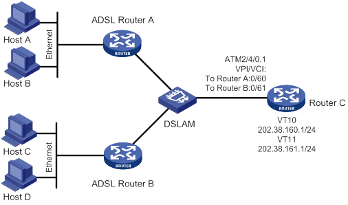
Configuration procedure
1. Configure Router C (PPPoEoA server):
# Create VT interfaces and configure IP addresses for them. Assign IP addresses to the remote ends.
<RouterC> system-view
[RouterC] interface virtual-template 10
[RouterC-Virtual-Template10] ip address 202.38.160.1 255.255.255.0
[RouterC-Virtual-Template10] remote address 202.38.162.1
[RouterC-Virtual-Template10] quit
[RouterC] interface virtual-template 11
[RouterC-Virtual-Template11] ip address 202.38.161.1 255.255.255.0
[RouterC-Virtual-Template11] remote address 202.38.162.2
[RouterC-Virtual-Template11] quit
# Create VE interfaces, and enable them to carry PPP.
[RouterC] interface virtual-ethernet 2/4/1
[RouterC-Virtual-Ethernet2/4/1] pppoe-server bind virtual-template 10
[RouterC-Virtual-Ethernet2/4/1] quit
[RouterC] interface virtual-ethernet 2/4/0
[RouterC-Virtual-Ethernet2/4/0] pppoe-server bind virtual-template 11
[RouterC-Virtual-Ethernet2/4/0] quit
# Create PVCs, and enable them to carry PPPoE.
[RouterC] interface atm 2/4/0.1
[RouterC-ATM2/4/0.1] pvc to_adsl_a 0/60
[RouterC-ATM2/4/0.1-pvc-to_adsl_a-0/60] map bridge virtual-ethernet 2/4/1
[RouterC-ATM2/4/0.1-pvc-to_adsl_a-0/60] quit
[RouterC-ATM2/4/0.1] pvc to_adsl_b 0/61
[RouterC-ATM2/4/0.1-pvc-to_adsl_b-0/61] map bridge virtual-ethernet 2/4/0
2. Configure Router A (PPPoEoA client):
# Create dialer access group 1 and configure a dial access rule for it.
<RouterA> system-view
[RouterA] dialer-group 1 rule ip permit
# Create dialer interface Dialer 1 and enable bundle DDR on the interface.
[RouterA] interface dialer 1
[RouterA-Dialer1] dialer bundle enable
# Assign interface Dialer 1 to dialer access group 1.
[RouterA-Dialer1] dialer-group 1
# Configure the PPPoE client to operate in permanent online mode.
[RouterA-Dialer1] dialer timer idle 0
# Set the auto-dial interval of DDR to 1 second.
[RouterA-Dialer1] dialer timer autodial 1
# Enable IP address negotiation.
[RouterA-Dialer1] ip address ppp-negotiate
[RouterA-Dialer1] quit
# Create a VE interface and enable it to carry PPP.
[RouterA] interface virtual-ethernet 2/4/0
[RouterA-Virtual-Ethernet2/4/0] pppoe-client dial-bundle-number 1
[RouterA-Virtual-Ethernet2/4/0] quit
# Create a PVC and enable it to carry PPPoE.
[RouterA] interface atm 2/4/0
[RouterA-ATM2/4/0] pvc 0/60
[RouterA-ATM2/4/0-pvc-0/60] map bridge virtual-ethernet 2/4/0
3. Configure ADSL Router B in the same way ADSL Router A is configured.
Verifying the configuration
Both ADSL Router A and ADSL Router B can ping Router C successfully.
ATM PVC transmission priority configuration example
Network requirements
As shown in Figure 48, create PVC 1 and PVC 2 on the same ATM 155 Mbps interface. Each PVC is assigned 100 Mbps of bandwidth and is associated with the UBR service. Set the transmission priority of PVC 1 to 1 and that of PVC 2 to 3.
Configure Router A to distribute equal amount of traffic to Router B and Router C on the two PVCs and observe the statistics of received/sent/dropped packets.
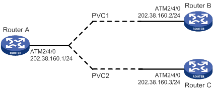
Configuration procedure
1. Configure Router A:
# Configure the ATM interface.
<RouterA> system-view
[RouterA] interface atm 2/4/0
[RouterA-Atm2/4/0] ip address 202.38.160.1 255.255.255.0
# Create two PVCs, and assign them different transmission priorities.
[RouterA-ATM2/4/0] pvc 1 0/33
[RouterA-ATM2/4/0-pvc-1-0/33] map ip 202.38.160.2
[RouterA-ATM2/4/0-pvc-1-0/33] service ubr 100000
[RouterA-ATM2/4/0-pvc-1-0/33] transmit-priority 1
[RouterA-ATM2/4/0-pvc-1-0/33] quit
[RouterA-ATM2/4/0] pvc 2 0/32
[RouterA-ATM2/4/0-pvc-2-0/32] map ip 202.38.160.3
[RouterA-ATM2/4/0-pvc-2-0/32] service ubr 100000
[RouterA-ATM2/4/0-pvc-2-0/32] transmit-priority 3
After two equal amount of traffic exceeding the ATM bandwidth are sent to Router B and Router C, you can use the display atm pvc-info command on Router B and Router C to view statistics of each PVC. You can make several tests and observe the average statistics. The output shows that the PVC with higher priority receives more packets than that with lower priority. The PVC with the higher priority takes preference in getting bandwidth. Other PVCs, regardless of their priority values, are treated equally in terms of bandwidth allocation.
Troubleshooting ATM
Link state error in IPoA application
Symptom
When IPoA is used, the link state is down.
Solution
· Verify that the optical fiber is connected correctly.
· Verify that the local IP address is configured.
· Verify that the PVC is successfully created.
Link report error in PPPoA application
Symptom
When PPPoA is used, the link cannot be up.
Solution
See "Link state error in IPoA application."
Ping failure
Symptom
The physical layer of the interfaces and the line protocol are both up, but they cannot ping each other.
Solution
· If IPoA is used, make sure the IP protocol address mapping is configured correctly. If the interfaces of two routers are connected back-to-back, the local PVC mapped to the remote IP address must have the same VPI/VCI value as the remote PVC mapped to the local IP address.
· If two routers are connected back-to-back, make sure at least one of interfaces uses internal transmission clock (master). If the routers are connected to the ATM network, the transmission clock must be set to line clock (slave).
· Verify that the ATM interfaces of the two sides are of the same type. For example, both sides use multi-mode fiber interfaces, single-mode fiber interfaces, or multi-mode fiber interfaces but connected using single-mode fiber. If a multi-mode fiber interface and a single-mode fiber interface are directly connected, they can communicate in most cases, but sometimes with frequent packet dropping and CRC errors.
· If the two ends use PPPoA, make sure their IP addresses and authentication parameters are correctly configured.
· If the output from the ping command shows that only small packets can pass, check the MTU settings of both router interfaces.
PVC state is down when ATM interface state is up
Symptom
The state of the ATM interface is up, but the PVC state is down.
Solution
Determine if this fault results from enabling OAM F5 Loopback cell transmission and retransmission detection. When two routers are connected, the VPI/VCI values of the PVCs on the two routers must be the same. If OAM F5 cell transmission and retransmission detection is enabled, and the VPI/VCI values of the two directly connected nodes are not the same, the local PVC state cannot change to up.
Ping failure after PPPoA configuration
Symptom
The PVC state is up, but after applications like PPPoA are configured, the remote node cannot be pinged.
Solution
Make sure the remote node supports the same application as configured on the local node. For example, if the local node uses PPPoA, the remote node must also use PPPoA.
If the remote node supports the same application configured on the local node, make sure the two sides use the same type of AAL5 encapsulation protocol. For example, if one side uses aal5snap and the other uses aal5mux, they cannot communicate. You can enable ATM packet debugging to get some clues about possible causes of the ping failure.
Managing a modem
This chapter describes how to manage and control the modems connected to the device.
Feature and hardware compatibility
This feature is available only on the following interface modules and interfaces:
· AM interface modules.
· ASE interface modules.
· AUX interfaces.
· SAE interface modules operating in asynchronous mode.
Modem management configuration task list
|
Remarks |
|
|
(Required.) Configuring modem services on a user line |
Configure a user line for incoming modem calls, outgoing modem calls, or both. |
|
(Required.) Setting the answer timeout timer |
Increase the answer timeout timer on a slow link for a successful modem connection establishment. |
|
(Required.) Setting the modem answer mode |
You must set the modem answer mode on a user line to be the same as the connected modem. |
|
(Optional.) Enabling a modem to obtain caller numbers |
This task is for point of sale (POS) terminal access services. Perform this task if a bank front end processor requires the call numbers of POS terminals for terminal identification. |
|
(Optional.) Enabling modem callback |
Enable modem callback if the remote end connected to the modem requires a callback. |
|
(Optional.) Issuing an AT command to a modem |
N/A |
|
(Required.) Setting the country code of a modem |
You must set the correct country code for the modem to operate correctly. |
Configuring modem services on a user line
|
|
CAUTION: This task disconnects the modem connection that has been established on the user line. |
Perform this task to configure a user line for incoming modem calls, outgoing modem calls, or both.
To configure the modem access services on user lines:
|
Step |
Command |
Remarks |
|
1. Enter system view. |
system-view |
N/A |
|
2. Enter user line view. |
line { first-num1 [ last-num1 ] | { aux | tty } first-num2 [ last-num2 ] } |
This command is available on the following user lines: · TTY lines for the following interfaces: ? AM interface ? Asynchronous serial interface ? Asynchronous/synchronous serial interface operating in asynchronous mode · AUX line This command is not available on the console or VTY lines. To display the user line for an interface, use the display line command. |
|
3. Enable the modem to answer incoming calls, initiate outgoing calls, or both. |
modem enable { both | call-in | call-out } |
By default, a modem is disabled from answering incoming calls and initiating outgoing calls. |
Setting the answer timeout timer
The answer timeout timer sets the amount of time that the modem will wait for a call to establish. When the timer expires, the modem disconnects the call.
· If the modem is on the calling party side, the timer starts when the modem starts to dial.
· If the modem is on the called party side, the timer starts when the modem goes off hook.
To set the answer timeout timer on user lines:
|
Step |
Command |
Remarks |
|
1. Enter system view. |
system-view |
N/A |
|
2. Enter user line view. |
line { first-num1 [ last-num1 ] | { aux | tty } first-num2 [ last-num2 ] } |
This command is available on the following user lines: · TTY lines for the following interfaces: ? AM interface ? Asynchronous serial interface ? Asynchronous/synchronous serial interface operating in asynchronous mode · AUX line This command is not available on the console or VTY lines. To display the user line for an interface, use the display line command. |
|
3. Set the answer timeout timer. |
modem answer-timer time |
The default timer value is 60 seconds. |
Setting the modem answer mode
To ensure correct operation of the modem, set the auto-answer mode on the user line to be the same as the modem.
· Enable auto-answer mode if the modem is in auto-answer mode (the AA LED of the modem lights up). This setting prevents the router from issuing a duplicate answer command after the modem answers a call.
· Disable auto-answer mode if the modem is not in auto-answer mode.
|
Step |
Command |
Remarks |
|
1. Enter system view. |
system-view |
N/A |
|
2. Enter user line view. |
line { first-num1 [ last-num1 ] | { aux | tty } first-num2 [ last-num2 ] } |
This command is available on the following user lines: · TTY lines for the following interfaces: ? AM interface ? Asynchronous serial interface ? Asynchronous/synchronous serial interface operating in asynchronous mode · AUX line This command is not available on the console or VTY lines. To display the user line for an interface, use the display line command. |
|
3. Set the modem answer mode. |
·
Enable auto-answer mode: ·
Disable auto-answer mode: |
By default, auto-answer mode is disabled. |
Enabling a modem to obtain caller numbers
|
|
CAUTION: Performing this task disconnects the modem connection. |
This task is for point of sale (POS) terminal access services. It is available only on the TTY lines for AM interfaces.
Configure this command if a bank front end processor requires the router to send the call numbers of POS terminals for acknowledgment before it accepts data from the terminals.
For more information about POS terminal access services and caller number sending, see Terminal Access Configuration Guide.
To enable a modem to obtain caller numbers:
|
Step |
Command |
Remarks |
|
1. Enter system view. |
system-view |
N/A |
|
2. Enter the TTY user line view of an AM interface. |
line { first-num1 [ last-num1 ] | tty first-num2 [ last-num2 ] } |
N/A |
|
3. Enable the modem to obtain caller number. |
modem caller-number resolve [ ata-waiting-time time ] |
By default, a modem does not obtain the caller number when it accepts a call from a terminal. |
Enabling modem callback
The callback function enables a modem to disconnect an incoming call and calls back the calling party on request.
To enable modem callback:
|
Step |
Command |
Remarks |
|
1. Enter system view. |
system-view |
N/A |
|
2. Enable the callback function. |
modem callback |
By default, the callback function is disabled. |
Issuing an AT command to a modem
|
|
CAUTION: This task changes the modem operating state. Incorrect configuration can cause problems such as dial-up failure. When you perform this task, make sure you understand its impact on the modem access service. |
To send AT commands to a modem, you must first place the modem in AT command mode. To confirm that you can send AT commands, enter sendat at. The modem will return OK or 0 if it is ready to accept AT commands. For more information about commonly used AT commands, see Layer 3—WAN Configuration Guide.
To issue an AT command to a modem:
|
Step |
Command |
Remarks |
|
1. Enter system view. |
system-view |
N/A |
|
2. Enter interface view. |
interface interface-type interface-number |
This command is available on the following interfaces: · AM interface · Asynchronous serial interface · Asynchronous/synchronous serial interface in asynchronous mode · AUX interface |
|
3. Issue an AT command to a modem. |
sendat at-string |
One sendat command can issue one AT command. To send multiple AT commands to a modem, repeat the sendat command. |
Setting the country code of a modem
|
|
CAUTION: This task disconnects the modem connection. |
Modem encoding format differs with countries. You must configure the correct country code for a modem to function correctly. This task is available only on AM interfaces.
To set the country code of a modem:
|
Step |
Command |
Remarks |
|
1. Enter system view. |
system-view |
N/A |
|
2. Enter AM interface view. |
interface analogmodem interface-number |
N/A |
|
3. Set the country code. |
country-code area-name |
The default country code is united-states. |
Modem management configuration example
Network requirements
As shown in Figure 49, configure DDR and modem access services for Router A and Router B to establish a modem dial-up connection between the Serial 2/1/0 interfaces for data transmission.
For more information about DDR, see "Configuring DDR."
Configuration procedure
1. Configure Router A:
# Create dialer access group 1 and add a dial access rule to match call triggering traffic. The rule in this example permits any IP packets to trigger a call.
<RouterA> system-view
[RouterA] dialer-group 1 rule ip permit
# Configure the asynchronous/synchronous serial interface Serial 2/1/0 to operate in asynchronous mode and protocol mode.
[RouterA] interface serial 2/1/0
[RouterA-Serial2/1/0] physical-mode async
[RouterA-Serial2/1/0] async-mode protocol
# Assign the IP address 1.1.1.1/16 to Serial 2/1/0.
![]()
![]() [RouterA-Serial2/1/0]
ip address 1.1.1.1 255.255.0.0
[RouterA-Serial2/1/0]
ip address 1.1.1.1 255.255.0.0
# Enable traditional DDR on Serial 2/1/0.
[RouterA-Serial2/1/0] dialer circular enable
# Assign Serial 2/1/0 to dialer access group 1.
[RouterA-Serial2/1/0] dialer-group 1
# Set the dial string for calling a remote end as 666666 on Serial 2/1/0.
[RouterA-Serial2/1/0] dialer number 666666
[RouterA-Serial2/1/0] quit
# Configure user line 1 (the user line for Serial 2/0) for both incoming and outgoing modem calls.
[RouterA] line tty 1
[RouterA-line-tty1] modem enable both
2. Configure Router B:
# Create dialer access group 1 and add a dial access rule to match call triggering traffic. The rule in this example permits any IP packets to trigger a call.
<RouterB> system-view
[RouterB] dialer-group 1 rule ip permit
# Configure the asynchronous/synchronous serial interface Serial 2/1/0 to operate in asynchronous mode and protocol mode.
[RouterB] interface serial 2/1/0
[RouterB-Serial2/1/0] physical-mode async
[RouterB-Serial2/1/0] async-mode protocol
# Assign the IP address 2.2.2.2/16 to Serial 2/1/0.
![]()
![]() [RouterB-Serial2/1/0]
ip address 1.1.1.1 255.255.0.0
[RouterB-Serial2/1/0]
ip address 1.1.1.1 255.255.0.0
# Enable traditional DDR on Serial 2/1/0.
[RouterB-Serial2/1/0] dialer circular enable
# Assign Serial 2/1/0 to dialer access group 1.
[RouterB-Serial2/1/0] dialer-group 1
# Set the dial string to 888888 on Serial 2/1/0.
[RouterB-Serial2/1/0] dialer number 888888
[RouterB-Serial2/1/0] quit
# Configure user line 1 (the user line for Serial 2/0) for both incoming and outgoing modem calls.
[RouterB] line tty 1
[RouterB-line-tty1] modem enable both
Verifying the configuration
Verify that Router A and Router B can ping each other on their Serial 2/0 interfaces.
Troubleshooting modem faults
Symptom
An external modem is in an abnormal state. For example, the dial tone or busy tone keeps humming.
Solution
To resolve the problem:
1. Execute the shutdown and undo shutdown commands on the physical interface connected to the modem.
2. Power-cycle the modem.
3. If the problem persists, contact H3C Support.
Managing a 3G/4G modem
Overview
A 3G/4G modem connects a device to a 3G/4G network.
3G/4G modems include built-in 3G/4G modems, USB 3G/4G modems, and SIC-3G/4G modems. They are managed in cellular interface view.
· A USB 3G/4G modem is hot swappable. It is managed in a fixed cellular interface view. The cellular interface varies by the device model. Even if no USB 3G/4G modem is installed, you can enter the interface view. The cellular interface remains after the USB 3G/4G modem is removed from the router.
· A SIC-3G/4G modem is not hot swappable. When a SIC-3G modem is installed, the cellular interface is created based on the slot of the modem. When the SIC-3G/4G modem is removed, the system removes this cellular interface.
A cellular interface can be channelized into a serial or an Eth-channel interface. Both the serial and Eth-channel interfaces operate in protocol mode. The data link layer protocols of the serial interface and Eth-channel interface are PPP and Ethernet, respectively. The two interfaces support IP at the network layer.
The cellular interface of a 3G modem can only be channelized into a serial interface. The cellular interface of a 4G modem can only be channelized into an Eth-channel interface. Support for cellular interface channelization depends on the modem model, not the SIM card.
Feature and hardware compatibility
The device supports Huawei EC1261 CDMA USB 3G modems and the following Huawei WCDMA USB 3G modems:
· E173
· E261
· E303C
· E3131
· E303
· E303S
· E352
· E303H
· E3533
The device does not support USB 4G modems.
4G modems are not supported on the following routers:
· MSR830-6EI-GL
· MSR830-10EI-GL
· MSR830-6HI-GL
· MSR830-10HI-GL
Configuration restrictions and guidelines
Follow these restrictions and guidelines when you configure 3G/4G modem management:
· Do not remove a USB 3G/4G modem while it is transmitting data. As a best practice, execute the shutdown command to shut down the USB 3G/4G modem before removing it.
· A USB 3G/4G modem is not usable when the USB interface to which the modem is attached is shut down. For more information about shutting down a USB interface, see Fundamentals Configuration Guide.
· Configure PPP and DDR, and specify an IP address on the serial interface channelized from a cellular interface of a 3G modem as needed.
· Configure DDR and specify an IP address on the Eth-channel interface channelized from a cellular interface of a 4G modem as needed.
· Unless otherwise noted, the 3G/4G modem configuration in this document is saved in the NVM of the 3G/4G modem. To verify the configuration, use the display cellular command.
3G modem management configuration task list
|
Tasks at a glance |
|
(Optional.) Specifying the primary or secondary SIM card |
|
(Optional.) Associating 3G/4G link backup with a track entry |
|
(Optional.) Configuring PIN verification |
|
(Optional.) Configuring a trusted IMSI |
|
(Optional.) Configuring DM |
|
(Optional.) Setting the RSSI thresholds |
|
(Optional.) Issuing a configuration directive to a 3G/4G modem |
|
(Optional.) Configuring automatic reboot |
|
(Optional.) Configuring manual reboot |
4G modem management configuration task list
|
Tasks at a glance |
|
Configuring an IP address for an Eth-channel interface of a 4G modem |
|
(Optional.) Specifying the primary or secondary SIM card |
|
(Optional.) Associating 3G/4G link backup with a track entry |
|
(Optional.) Configuring PIN verification |
|
(Optional.) Configuring a trusted IMSI |
|
(Optional.) Configuring DM |
|
(Optional.) Setting the RSSI thresholds |
|
(Optional.) Issuing a configuration directive to a 3G/4G modem |
|
(Optional.) Configuring automatic reboot |
|
(Optional.) Configuring manual reboot |
|
(Optional.) Binding the IMSI of the SIM card to an interface |
Configuring a cellular interface for a 3G modem
|
Step |
Command |
Remarks |
|
1. Enter system view. |
system-view |
N/A |
|
2. Enter cellular interface view. |
controller cellular cellular-number |
N/A |
|
3. Configure a description for the cellular interface. |
description text |
By default, the description for a cellular interface is interface name Interface, for example, Cellular 2/4/0 Interface. |
|
4. Channelize the cellular interface into a synchronous/asynchronous serial interface. |
serial-set set-number |
This command names the serial interface as serial cellular-number:set-number. |
|
5. Bring up the cellular interface. |
undo shutdown |
By default, the cellular interface is up. |
Configuring a cellular interface for a 4G modem
|
Step |
Command |
Remarks |
|
1. Enter system view. |
system-view |
N/A |
|
2. Enter cellular interface view. |
controller cellular cellular-number |
N/A |
|
3. Configure a description for the cellular interface. |
description text |
By default, the description for a cellular interface is interface name Interface, for example, Cellular 2/4/0 Interface. |
|
4. Channelize the cellular interface into an Eth-channel interface. |
This command names the Eth-channel interface as eth-channel cellular-number:channel-number. |
|
|
5. Bring up the cellular interface. |
undo shutdown |
By default, the cellular interface is up. |
Configuring an Eth-channel interface for a 4G modem
|
Step |
Command |
Remarks |
|
1. Enter system view. |
system-view |
N/A |
|
2. Enter Eth-channel interface view. |
N/A |
|
|
3. Configure a description for the Eth-channel interface. |
description text |
By default, the description for an Eth-channel interface is interface name Interface, for example, Echannel 2/4/0:0 Interface. |
|
4. Set the MTU for the Eth-channel interface. |
By default, the MTU for an Eth-channel interface is 1500 bytes. |
|
|
5. Set the expected bandwidth of the Eth-channel interface. |
By default, the expected bandwidth (in kbps) of an Eth-channel is the interface baud rate divided by 1000. The baud rate of an Eth-channel interface is 100 Mbps. |
|
|
6. Restore the default settings for the Eth-channel interface. |
default |
N/A |
|
7. Bring up the Eth-channel interface. |
undo shutdown |
By default, an Eth-channel interface is up. |
Configuring an IP address for an Eth-channel interface of a 4G modem
An Eth-channel interface can communicate with other devices only after it obtains an IP address. You can configure an IP address for an Eth-channel interface in the following ways:
· DHCP—The Eth-channel interface obtains the modem's IP address as its own IP address through DHCP. The modem's IP address is automatically allocated by the service provider.
· Modem manufacturer's proprietary protocol—The Eth-channel interface obtains the modem's IP address as its own IP address through the modem manufacturer's proprietary protocol. The modem's IP address is automatically allocated by the service provider.
· Manual configuration.
The ways for the Eth-channel interface to obtain an IP address are mutually exclusive. The most recent configuration overrides the previous one.
|
|
TIP: Changing the IP address will result in dialup interruption. Immediate re-dialup upon interruption might not be supported by service providers. |
To configure an IP address for an Eth-channel interface:
|
Step |
Command |
Remarks |
|
|
8. Enter system view. |
system-view |
N/A |
|
|
9. Enter Eth-channel interface view. |
interface eth-channel interface-number |
N/A |
|
|
10. Configure an IP address for the Eth-channel interface in one of the three ways. |
Obtain an IP address by using DHCP. |
By default, an Eth-channel interface does not obtain an IP address by using DHCP. For more information, see Layer 3—IP Services Command Reference. |
|
|
Obtain an IP address by using the modem-manufacturer's proprietary protocol. |
By default, an Eth-channel interface does not obtain an IP address by using the modem-manufacturer's proprietary protocol. |
||
|
Configure an IP address manually. |
{ ip | ipv6 } address ip-address { mask-length | mask } [ sub ] |
By default, no IP address is configured for an Eth-channel interface. |
|
Configuring a 3G/4G network
Wireless networks include GSM, CDMA2000 (CDMA-1x RTT and CDMA-EVDO), TD-SCDMA, WCDMA, and LTE networks. Both 3G and 4G modems can access GSM, CDMA2000, TD-SCDMA, and WCDMA networks. Only 4G modems can access LTE networks. Support for accessing which networks depends on the modem model.
A 3G/4G modem is used to search a public land mobile network (PLMN) for accessible mobile networks. A PLMN is uniquely identified by the mobile country code (MCC) and the mobile network code (MNC). Some 3G/4G modems can automatically access a mobile network. To manually specify a mobile network for a 3G modem, first search for available mobile networks.
A 4G modem can automatically use an available band and register with a mobile network. You can also specify a band for a 4G modem. When a 4G modem uses an incorrect band, specify a band for it.
To configure a 3G/4G network:
|
Step |
Command |
Remarks |
|
1. Enter system view. |
system-view |
N/A |
|
2. Enter cellular interface view. |
controller cellular interface-number |
N/A |
|
3. (Optional.) Search for PLMNs. |
plmn search |
N/A |
|
4. Configure a PLMN searching mode. |
plmn select { auto | manual mcc mnc } |
The default setting depends on the modem model. |
|
5. Specify the network service to which the modem connects. |
mode { 1xrtt | auto | evdo | gsm | gsm-precedence | hybrid | lte | td | td-precedence | wcdma | wcdma-precedence } |
The default setting for this command and support for the arguments depend on the modem model. |
|
6. (Optional.) Specify a GSM band. |
gsm band { egsm900 | gsm450 | gsm480 | gsm750 | gsm850 | gsm1800 | gsm1900 | pgsm900 | rsgm900 } |
By default, no GSM band is specified. |
|
7. (Optional.) Specify a WCDMA band. |
wcdma band { wcdma800 | wcdma850 | wcdma900 | wcdma1700ip | wcdma1700us | wcdma1800 | wcdma1900 | wcdma2100 | wcdma2600 } |
By default, no WCDMA band is specified. |
|
8. (Optional.) Specify an LTE band. |
lte band band-number |
The default setting for this command varies by 4G modem model. |
Configuring parameter profiles
Configuring a parameter profile
A parameter profile defines the following items:
· The access point with which a 3G/4G modem is associated.
· The authentication mode in which the service provider authenticates the 3G/4G modem.
To configure a parameter profile for a 3G modem:
|
Step |
Command |
Remarks |
|
1. Enter system view. |
system-view |
N/A |
|
2. Enter cellular interface view. |
controller cellular interface-number |
N/A |
|
3. Create a parameter profile. |
profile create profile-number { dynamic | static apn } authentication-mode { none | { chap | pap } user username [ password password ] } |
If you specify none, no authentication is performed. If you specify chap or pap, configure the username and password according to the requirement of the service provider. The default setting depends on the modem model. |
|
4. (Optional.) Delete the parameter profile. |
profile delete profile-number |
N/A |
To configure a parameter profile for a 4G modem:
|
Step |
Command |
Remarks |
|
1. Enter system view. |
system-view |
N/A |
|
2. Create a profile. |
apn-profile profile-name |
By default, no profiles exist. |
|
3. Specify the PDP data carrying protocol. |
pdp-type { ipv4 | ipv6 | ipv4v6 } |
By default, the PDP data carrying protocol is IPv4 and IPv6. |
|
4. Configure an APN. |
apn { dynamic | static apn } |
By default, no APNs exist. |
|
5. Specify an authentication mode for the profile. |
authentication-mode { pap | chap | pap-chap } user user-name password { cipher | simple } string |
By default, no authentication mode is specified for a profile. |
|
6. Specify a separator for the IMSI/SN binding authentication information. |
attach-format imsi-sn split splitchart |
By default, no separator is specified for the IMSI/SN binding authentication information. |
|
7. Return to system view |
quit |
N/A |
|
8. (Optional.) Delete the profile. |
undo apn-profile profile-name |
N/A |
Specifying the primary and backup profiles
By default, profile 1 is used for 3G/4G modem dialup. The dialup fails if profile 1 does not exist.
You can also specify the primary and backup profiles for 3G/4G modem dialup. The primary profile always has priority over the backup profile. For each dialup connection establishment, the 3G or 4G modem uses the backup profile only when it has failed to dial up using the primary profile.
You must configure the same username and password for the primary and backup profiles.
To specify the primary and backup profiles for a 3G modem:
|
Step |
Command |
Remarks |
|
1. Enter system view. |
system-view |
N/A |
|
2. Enter cellular interface view. |
controller cellular interface-number |
N/A |
|
3. Specify the primary and backup profiles |
profile main main-profile-number backup backup-profile-number |
By default, profile 1 is used for 3G modem dialup. |
To specify the primary and backup profiles for a 4G modem:
|
Step |
Command |
Remarks |
|
1. Enter system view. |
system-view |
N/A |
|
2. Enter Eth-channel interface view. |
interface eth-channel interface-number |
N/A |
|
3. Specify primary and backup profiles for the 4G modem. |
apn-profile apply profile-name [ backup profile-name ] |
By default, no profiles are specified for 4G modem dialup. |
Specifying the primary or secondary SIM card
This feature is supported only on MSR810-LM and MSR810-LUS routers and routers installed with SIC-4G-CNDE interface modules.
On a device that uses dual SIM card, you can specify the use of the secondary SIM card when one of the following problems occurs:
· The 3G/4G link signals of the primary SIM card are weak.
· The service provider network that the primary SIM card connects to is unavailable.
· The primary SIM card has failed.
If the problems of the primary SIM card are resolved, you can use this command to specify the use of the primary SIM card.
To specify the primary or secondary SIM card:
|
Step |
Command |
Remarks |
|
1. Enter system view. |
system-view |
N/A |
|
2. Enter cellular interface view. |
controller cellular interface-number |
N/A |
|
3. Specify the primary or secondary SIM card. |
sim switch-to card-number |
By default, a 3G/4G modem uses the primary SIM card. |
|
4. Enable the 3G/4G modem to automatically switch back to the primary SIM card. |
sim switch-back enable [ wait-time time ] |
By default, automatic switchback to the primary SIM card is disabled. |
Associating 3G/4G link backup with a track entry
This feature is supported only on MSR810-LMS/810-LUS routers and routers installed with SIC-4G-CNDE interface modules.
After you enable this feature, the system uses a track entry to monitor the status of the primary 3G/4G link. When the track entry state changes from Positive to Negative, the secondary 3G/4G link takes over.
To associate 3G/4G link backup with a track entry:
|
Step |
Command |
Remarks |
|
1. Enter system view. |
system-view |
N/A |
|
2. Enter cellular interface view. |
controller cellular interface-number |
N/A |
|
3. Associate 3G/4G link backup with a track entry |
sim backup enable track entry-number |
By default, 3G/4G link backup is not associated with a track entry. |
Configuring PIN verification
A UIM card is used in the CDMA network and a SIM card is used in other mobile networks. Each SIM/UIM card has a Personal Identification Number (PIN). PIN verification prevents unauthorized access to the SIM/UIM card.
To perform PIN verification, you need to save the PIN of the SIM/UIM card on the device by using the pin verify command and enable PIN verification. The pin verify command can be executed before and after you enable PIN verification. After the PIN is saved on the device, the PIN is used for verification automatically when required.
When PIN verification is enabled, PIN verification is performed after you perform any of the following tasks:
· Install a 3G/4G modem.
· Reboot the device where a USB 3G/4G modem is attached.
· Execute the modem reboot command to reboot a 3G/4G modem.
· Hot swap a USB 3G/4G modem.
· Cold boot the device where a SIC-3G/4G modem is installed.
If PIN verification fails after a maximum number of attempts, the SIM/UIM card is locked, and a PIN Unlocking Key (PUK) is required to unlock the card. The maximum number of attempts depends on the 3G/4G modem model.
To configure PIN verification:
|
Step |
Command |
Remarks |
|
1. Enter system view. |
system-view |
N/A |
|
2. Enter cellular interface view. |
controller cellular interface-number |
N/A |
|
3. Enable PIN verification. |
pin verification enable [ pin ] |
The default setting depends on the modem model. Requirement for the current PIN varies by device model. |
|
4. Specify the PIN for verification. |
pin verify { cipher | simple } string |
By default, no PIN is configured on a device for 3G/4G modem verification. This command saves the PIN on the device. |
|
5. (Optional.) Specify a PUK to unlock the SIM/UIM card. |
pin unlock puk new-pin |
After the SIM/UIM card is unlocked, execute the pin verify command to save the new PIN on the device. |
|
6. (Optional.) Modify the PIN of the SIM/UIM card. |
pin modify current-pin new-pin |
The new PIN is saved in the SIM/UIM card. After the PIN is modified, execute the pin verify command to save the new PIN on the device. |
Configuring a trusted IMSI
For a successful dialup, configure the IMSI on the SIM card as a trusted IMSI.
To configure a trusted IMSI:
|
Step |
Command |
Remarks |
|
1. Enter system view. |
system-view |
N/A |
|
2. Enter cellular interface view. |
controller cellular interface-number |
N/A |
|
3. Configure a trusted IMSI. |
trust-imsi string-imsi |
You can configure a maximum of 16 trusted IMSIs. |
Configuring DM
Diagnostic and monitoring (DM) allows third-party debugging tools to diagnose and monitor the 3G/4G modem through cellular interface debugging output. For more information about DM, see related 3G/4G modem user manuals.
DM is supported on SIC-4G modems, and EM770, EM660, and EM770W 3G modems.
To enable DM:
|
Step |
Command |
Remarks |
|
1. Enter system view. |
system-view |
N/A |
|
2. Enter cellular interface view. |
controller cellular interface-number |
N/A |
|
3. Enable DM. |
dm-port open |
The default setting depends on the modem model. |
Setting the RSSI thresholds
|
Step |
Command |
Remarks |
|
1. Enter system view. |
system-view |
N/A |
|
2. Enter cellular interface view. |
controller cellular interface-number |
N/A |
|
3. Set the RSSI thresholds. |
rssi { gsm | 1xrtt | evdo | lte } { low lowthreshold | medium mediumthreshold } |
The lower and upper RSSI thresholds for a 3G/4G modem are –150 dBm and 0 dBm, respectively. The value of lowthreshold cannot be smaller than the value of mediumthreshold because the system automatically adds a negative sign to the RSSI thresholds. |
Issuing a configuration directive to a 3G/4G modem
|
|
CAUTION: Configuration directives might cause malfunction of a 3G/4G modem. When you issue a configuration directive to the modem, make sure you understand the impact on the 3G/4G modem. |
To issue a configuration directive to a 3G/4G modem:
|
Step |
Command |
Remarks |
|
1. Enter system view. |
system-view |
N/A |
|
2. Enter cellular interface view. |
controller cellular interface-number |
N/A |
|
3. Issue a configuration directive to the 3G/4G modem. |
sendat at-string |
N/A |
Configuring automatic reboot
The 3G modem might malfunction in an unstable 3G network or when the application environment changes. During a malfunction, the modem cannot respond to the device's requests or configuration commands. If the device does not receive any responses from the 3G modem within the timeout interval, a response failure occurs. When the number of consecutive response failures reaches the threshold, the device restarts the 3G modem automatically.
The device does not restart the 3G modem when the 3G modem has not made a successful dialup since the last restart. This restriction avoids repeated restarts of the 3G modem when there are configuration errors.
To configure automatic reboot:
|
Step |
Command |
Remarks |
|
1. Enter system view. |
system-view |
N/A |
|
2. Enter cellular interface view. |
controller cellular interface-number |
N/A |
|
3. Configure the response timeout and the threshold for the number of consecutive timeouts to enable automatic reboot of the 3G/4G modem. |
modem response timer time auto-recovery threshold |
By default, the response timeout is 10 seconds and the consecutive timeout threshold is 3. The configuration is saved on the device rather than the 3G/4G modem. |
Configuring manual reboot
|
Step |
Command |
Remarks |
|
1. Enter system view. |
system-view |
N/A |
|
2. Enter cellular interface view. |
controller cellular interface-number |
N/A |
|
3. Manually reboot the 3G/4G modem. |
modem reboot |
A 3G/4G modem can automatically detect running errors and reboot. If the 3G/4G modem fails to reboot by itself, you can use this command to manually reboot it. |
Binding the IMSI of the SIM card to an interface
This feature is not supported on distributed devices and IRF devices.
The device must support PPP LCP negotiation of the IMSI/SI when it acts as a LAC to access the LNS in LAC-auto-initiated mode. After you bind the IMSI on the SIM card to a virtual PPP interface, the packets sent by the device carry the IMSI.
To bind the IMSI of the SIM card to an interface:
|
Step |
Command |
Remarks |
|
1. Enter system view. |
system-view |
N/A |
|
2. Enter cellular interface view. |
controller cellular interface-number |
N/A |
|
3. Bind the IMSI on the SIM card to an interface. |
imsi bind interface-type interface-number |
By default, the IMSI on the SIM card is not bound to any interface. |
Displaying and maintaining 3G/4G modem information
Execute display commands in any view and the reset command in user view.
|
Task |
Command |
|
Display the call connection information for a 3G/4G modem. |
display cellular [ interface-number ] |
|
Display information about a cellular interface. |
display controller [ cellular [ interface-number ] ] |
|
Display information about a channelized Eth-channel interface. |
display interface [ eth-channel [ channel-id ] ] [ brief [ description | down ] ] |
|
Display information about a channelized serial interface. |
display interface [ serial [ channel-id ] ] [ brief [ description | down ] ] |
|
Clear the statistics for a cellular interface. |
reset counters controller [ cellular [ interface-number ] ] |
|
Clear the statistics for an Eth-channel interface. |
|
|
Clear the statistics on a channelized serial interface. |
reset counters interface [ serial [ channel-id ] ] |
3G/4G modem management configuration examples
3G modem management configuration example
Network requirements
As shown in Figure 50:
· The router provides a USB 3G or SIC-3G modem.
· The PC dials up to access a 3G network through Dial-on-Demand Routing (DDR).
For more information about DDR dialup, see "Configuring DDR."

Configuration procedure
# Create dialer group 1 and configure DDR to place calls for IP packets.
<Router> system-view
[Router] dialer-group 1 rule ip permit
# Channelize the cellular interface into a synchronous/asynchronous serial interface.
[Router] controller cellular 2/4/0
[Router-Cellular2/4/0] serial-set 0
[Router-Cellular2/4/0] quit
# Assign an IP address to interface Serial 2/4/0:0.
[Router] interface serial 2/4/0:0
![]()
![]() [Router-Serial2/4/0:0]
ip address ppp-negotiate
[Router-Serial2/4/0:0]
ip address ppp-negotiate
# Enable traditional DDR on interface Serial 2/4/0:0.
[Router-Serial2/4/0:0] dialer circular enable
# Associate interface Serial 2/4/0:0 with dialer group 1.
[Router-Serial2/4/0:0] dialer-group 1
# Set the interval for DDR to make the next call attempt to 5 seconds.
[Router-Serial2/4/0:0] dialer timer autodial 5
# Configure the dial string for placing calls as 666666.
[Router-Serial2/4/0:0] dialer number 666666
[Router-Serial2/4/0:0] quit
# Enable modem dial-in and dial-out on user line TTY 1.
[Router] line tty 1
[Router-line-tty1] modem enable both
4G modem management configuration example
Network requirements
As shown in Figure 51:
· The router provides a USB 4G or SIC-4G modem.
· The PC dials up to access an LTE network through Dial-on-Demand Routing (DDR).
For more information about DDR dialup, see "Configuring DDR."
Configuration procedure
# Configure dialer group 1 and configure DDR to place calls for IP packets.
<Router> system-view
[Router] dialer-group 1 rule ip permit
# Channelize the cellular interface into an Eth-channel interface.
[Router] controller cellular 2/4/0
[Router-Cellular2/4/0] eth-channel 0
[Router-Cellular2/4/0] quit
# Configure an IP address for Eth-channel 2/4/0:0.
[Router] interface eth-channel 2/4/0:0
[Router-Eth-channel2/4/0:0] ip address cellular-alloc
# Enable traditional DDR on Eth-channel 2/4/0:0.
[Router-Eth-channel2/4/0:0] dialer circular enable
# Associate Eth-channel 2/4/0:0 with dialer group 1.
[Router-Eth-channel2/4/0:0] dialer-group 1
# Set the interval for DDR to make the next call attempt to 5 seconds.
[Router-Eth-channel2/4/0:0] dialer timer autodial 5
# Configure the dial string for placing calls as 666666.
[Router-Eth-channel2/4/0:0] dialer number 666666
Troubleshooting 3G and 4G modem management
3G/4G modem failure
Symptom
A 3G/4G modem fails to function correctly. For example, the 3G/4G modem receives no signals or fails to connect to service providers' networks.
Solution
To resolve the issue:
1. Execute the shutdown command and the undo shutdown command on the cellular interface.
2. If the 3G/4G modem still fails to function, execute the modem reboot command on the cellular interface.
3. If the issue persists, contact H3C Support.
Configuring DDR
Overview
As shown in Figure 52, routers use dial-on-demand routing (DDR) for the following purposes:
· Setting up a dialup connection over PSTN/ISDN when communication needs arise.
· Tearing down the connection when the communication is complete.
Figure 52 DDR communication process
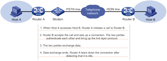
In addition to PSTN/ISDN, Ethernet and ATM can use DDR to implement access control. For more information, see "Configuring PPPoE" and "Configuring ATM."
Interfaces in DDR
DDR uses the following dialup interfaces:
· Physical interfaces—Include the following interfaces:
? Asynchronous serial interfaces.
? Synchronous/asynchronous serial interfaces operating in asynchronous mode.
? AM interfaces.
? AUX interfaces.
? ISDN BRI interfaces.
? ISDN PRI interfaces.
? Cellular interfaces.
· Dialer interfaces—Logical interfaces used for DDR parameter configurations.
DDR implementations
DDR supports traditional DDR and bundle DDR.
Traditional DDR
You can configure traditional DDR by using the following methods:
· Configure DDR parameters directly on a physical interface.
The router places or receives calls through the physical interface.
The physical interface can have one or more call destinations.
This method applies when only one interface places or receives calls.
· Configure DDR parameters on a dialer interface.
A dialer interface is associated with a group of physical interfaces and selects a physical interface to place or receive calls.
A dialer interface can have one or more call destinations. A dialer interface with multiple call destinations can use any associated physical interface to place calls to any of the call destinations.
A physical interface can belong to only one dialer interface.
This method applies when one or more interfaces place or receive calls.
Bundle DDR
When using bundle DDR, you can configure DDR parameters only on a dialer interface.
A dialer interface corresponds to a dialer bundle. A dialer bundle can contain multiple physical interfaces. You can assign a priority to each physical interface in the dialer bundle. Each time a call is placed, the highest-priority physical interface available is selected. If multiple physical interfaces with the highest priority are available, these interfaces are selected in a round-robin manner.
A dialer interface can have only one call destination.
A physical interface can belong to multiple dialer bundles and can be used by multiple dialer interfaces at different times.
Comparison of traditional DDR and bundle DDR
Traditional DDR is based on one-to-one bindings between dial services and physical interfaces. A new dial service requires a new physical interface. As a result, traditional DDR has poor extensibility.
|
|
NOTE: A dial rule (configured by using the dialer-group rule command) defines one dial service. |
Figure 53 Relationships among physical interfaces, dialer interfaces, and call destinations in traditional DDR
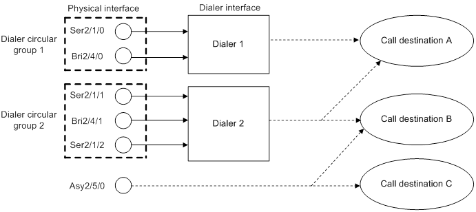
Bundle DDR is simpler and more flexible than traditional DDR. Bundle DDR separates physical interface configuration and logical configuration for calls and allows one-to-many bindings between dial services and physical interfaces. A physical interface can serve multiple dial services.
Figure 54 Relationships among physical interfaces, dialer interfaces, and call destinations in bundle DDR
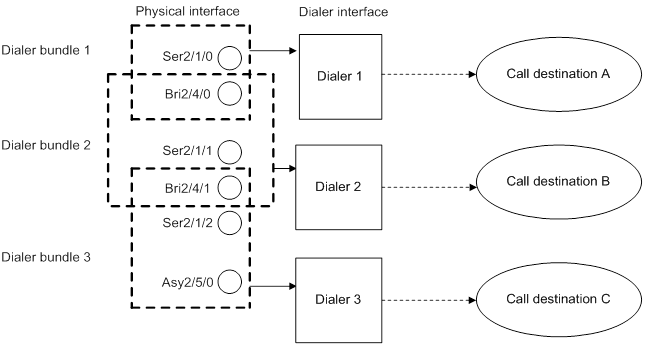
DDR types
Depending on how DDR calls are triggered, DDR includes packet-triggered DDR, auto-dial DDR, and route-triggered DDR.
Packet-triggered DDR
You can define packets on a dialup interface as interesting and uninteresting by configuring access control rules. Only interesting packets trigger outgoing calls and reset the link idle-timeout timer.
Before a dialup connection is established, uninteresting packets will be dropped. After a dialup connection is established, uninteresting packets can be forwarded. When the link idle-timeout timer expires, DDR disconnects the connection.
For more information about interesting and uninteresting packets, see "Associating a dial rule with a dialup interface."
Auto-dial DDR
DDR automatically initiates a dialup connection to the remote end upon router startup without requiring a triggering packet. If the connection cannot be established, it will retry at the auto-dial interval. The established connection will not disconnect due to the idle-timeout timer expiration.
Route-triggered DDR
You can configure networks to be monitored and then associate a dialup interface with the networks. When no routes to the monitored networks exist, DDR creates a secondary link from the dialup interface to forward traffic. After the secondary link is activated, the system regularly checks the status of the primary link. When the primary link recovers, the secondary link is disconnected immediately or after the secondary link disconnection delay, depending on your configuration.
Compatibility information
Feature and hardware compatibility
MSR3600-28-SI and MSR3600-51-SI routers do not support DDR.
Command and hardware compatibility
Commands and descriptions for centralized devices apply to the following routers:
· MSR810/810-W/810-W-DB/810-LM/810-W-LM/810-10-PoE/810-LM-HK/810-W-LM-HK/810-LMS/810-LUS.
· MSR2600-6-X1/2600-10-X1.
· MSR 2630.
· MSR3600-28/3600-51.
· MSR3600-28-SI/3600-51-SI.
· MSR3610-X1/3610-X1-DP/3610-X1-DC/3610-X1-DP-DC.
· MSR 3610/3620/3620-DP/3640/3660.
· MSR810-LM-GL/810-W-LM-GL/830-6EI-GL/830-10EI-GL/830-6HI-GL/830-10HI-GL/2600-6-X1-GL/3600-28-SI-GL.
Commands and descriptions for distributed devices apply to the following routers:
· MSR5620.
· MSR 5660.
· MSR 5680.
IPv6-related parameters are not supported on the following routers:
· MSR810/810-W/810-W-DB/810-LM/810-W-LM/810-10-PoE/810-LM-HK/810-W-LM-HK/810-LMS/810-LUS.
· MSR3600-28-SI/3600-51-SI.
DDR configuration task lists
Packet-triggered DDR configuration task list
|
Tasks at a glance |
|
(Required.) Configuring basic settings for DDR · Configuring physical interfaces · Configuring link layer/network/routing protocols on the dialup interface |
|
(Required.) Associating a dial rule with a dialup interface |
|
(Required.) Perform one of the following tasks: ? Configuring an interface to place calls ? Configuring an interface to receive calls |
|
(Required.) Configuring attributes for a dialup interface |
|
(Optional.) Configuring MP for DDR |
|
(Optional.) Configuring PPP callback |
|
(Optional.) Configuring ISDN caller number callback |
|
(Optional.) Disconnecting a dialup link |
Auto-dial DDR configuration task list
|
Tasks at a glance |
|
(Required.) Configuring basic settings for DDR · Configuring physical interfaces · Configuring link layer/network/routing protocols on the dialup interface |
|
(Required.) Perform one of the following tasks: ? Configuring an interface to place calls ? Configuring an interface to receive calls |
|
(Required.) Configuring attributes for a dialup interface |
|
(Optional.) Configuring MP for DDR |
|
(Required.) Configuring auto-dial |
|
(Optional.) Disconnecting a dialup link |
Route-triggered DDR configuration task list
|
Tasks at a glance |
|
(Required.) Configuring basic settings for DDR · Configuring physical interfaces · Configuring link layer/network/routing protocols on the dialup interface |
|
(Required.) Perform one of the following tasks: ? Configuring an interface to place calls ? Configuring an interface to receive calls |
|
(Required.) Configuring attributes for a dialup interface |
|
(Optional.) Configuring MP for DDR |
|
(Required.) Configuring dynamic route backup through DDR · Creating a dynamic route backup group · Assigning a dialup interface to a dynamic route backup group |
|
(Optional.) Disconnecting a dialup link |
Configuring basic settings for DDR
Configuring physical interfaces
The router uses ISDN BRI and ISDN PRI interfaces to connect to an ISDN network. It uses asynchronous serial interfaces, synchronous/asynchronous serial interfaces, AM interfaces, and AUX interfaces to connect to a PSTN network. For information about configuring these physical interfaces, see Interface Configuration Guide.
When you configure a synchronous/asynchronous serial interface, follow these guidelines:
· If the connected modem is asynchronous, perform the following tasks:
? Configure the interface as an asynchronous interface by using the physical-mode async command and to operate in protocol mode by using the async-mode protocol command.
? Configure the call-in/call-out rights for the modem on the corresponding user line for the interface.
· If the connected modem is synchronous, configure the interface as a synchronous serial interface by using the physical-mode sync command.
For more information about modem management, see "Managing a modem."
Configuring link layer/network/routing protocols on the dialup interface
Dialup interfaces support PPP, IP, RIP, and OSPF. For information about configuring these protocols, see "Configuring PPP and MP," Layer 3—IP Services Configuration Guide, and Layer 3—IP Routing Configuration Guide.
When you configure PPP, follow these guidelines:
· For traditional DDR, configure PPP commands on the same interface as DDR parameters.
· For bundle DDR:
? On the calling side, perform the following tasks:
- Configure PPP commands on dialer interfaces.
- Configure the same PPP commands on physical interfaces to ensure successful PPP link parameters negotiation.
? On the called side, configure PPP commands on physical interfaces.
Associating a dial rule with a dialup interface
A dial rule determines when a dialup interface initiates DDR calls. You need to configure dial rules only on the initiator of DDR calls.
You can configure a dial rule to match only IP packets or use an ACL to match packets.
Permitted protocol packets or packets that match a permit statement of an ACL are interesting packets. When receiving an interesting packet, DDR performs one of the following operations:
· Sends it out and resets the idle-timeout timer if a link is present.
· Initiates a new call to establish a link if no link is present.
Denied protocol packets or packets that match a deny statement of an ACL are uninteresting packets. When receiving an uninteresting packet, DDR performs one of the following operations:
· Sends it out without resetting the idle-timeout timer if a link is present.
· Drops it if no link is present.
For DDR to forward packets correctly, configure a dial rule and associate it with the dialup interface.
To associate a dial rule with a dialup interface:
|
Step |
Command |
Remarks |
|
1. Enter system view. |
system-view |
N/A |
|
2. Create a dialer group and configure a dial rule. |
dialer-group group-number rule { ip | ipv6 } { deny | permit | acl { acl-number | name acl-name } } |
By default, no dialer group is created. |
|
3. Enter dialup interface view. |
interface interface-type interface-number |
N/A |
|
4. Associate the dialer group with the dialup interface. |
dialer-group group-number |
By default, a dialup interface is not associated with a dialer group. A dialup interface can be associated with only one dialer group. |
Configuring traditional DDR
For traditional DDR, you can configure PAP or CHAP authentication (see "Configuring PPP and MP"). As a best practice, configure PAP or CHAP authentication for security purposes.
When you configure PAP or CHAP authentication, follow these guidelines:
· Configure PAP or CHAP authentication on a physical interface if you configure DDR parameters directly on the physical interface.
· Configure PAP or CHAP authentication on the dialer interface if you configure DDR parameters through a dialer circular group.
Configuring an interface to place calls
To configure an interface to place calls, enable DDR and configure dial strings.
When you configure an interface to place calls, follow these guidelines:
· To configure an interface to place calls to a single site, use the dialer number or dialer route command to specify the dial string to reach the site. To configure an interface to place calls to multiple sites, use the dialer route command multiple times to specify the dial strings to reach the sites.
· You can use the dialer route command to configure multiple dial strings for a single destination for dial backup. If a dial string fails to reach the destination, another dial string will be used.
· To configure an interface to place calls, you can make the configuration on the physical interface or through a dialer circular group. To configure multiple interfaces to place calls, you can make the configuration only through a dialer circular group.
Configuring an interface to place calls directly on a physical interface
|
Step |
Command |
Remarks |
|
1. Enter system view. |
system-view |
N/A |
|
2. Enter physical interface view. |
interface interface-type interface-number |
N/A |
|
3. Enable traditional DDR. |
dialer circular enable |
By default, traditional DDR is disabled. |
|
4. Configure a dial string. |
· dialer number dial-number · dialer route ip next-hop-address [ mask network-mask-length ] [ vpn-instance vpn-instance-name ] dial-number number [ broadcast ] |
By default, no dial string is configured. |
Configuring an interface to place calls through a dialer circular group
|
Step |
Command |
Remarks |
|
1. Enter system view. |
system-view |
N/A |
|
2. Create a dialer interface and enter its view. |
interface dialer number |
N/A |
|
3. Enable traditional DDR on the interface. |
dialer circular enable |
By default, traditional DDR is disabled on an interface. |
|
4. Configure a dial string. |
· dialer number dial-number · dialer route ip next-hop-address [ mask network-mask-length ] [ vpn-instance vpn-instance-name ] dial-number number [ interface interface-type interface-number ] [ broadcast ] |
By default, no dial string is configured. |
|
5. Return to system view. |
quit |
N/A |
|
6. Enter physical interface view. |
interface interface-type interface-number |
N/A |
|
7. Assign the physical interface to a dialer circular group. |
dialer circular group number |
By default, a physical interface does not belong to a dialer circular group. Make sure the number arguments in the interface dialer and dialer circular group commands use the same value. |
|
8. Configure the priority of the physical interface in the dialer circular group. |
dialer priority priority |
The default setting is 1. When configuring one interface to place calls, you do not need to configure this command. When configuring multiple interfaces to place calls, you need to configure this command. Each time a call is placed, the highest-priority physical interface available is selected. If one of the available physical interfaces with the highest priority is selected, the interfaces are selected in a round-robin manner. |
Configuring an interface to receive calls
To configure an interface to receive calls, you only need to enable DDR on the interface.
For the receiving interface to authenticate the caller, configure the dialer route ip next-hop-address user hostname command. Then, if the IP address and host name of the caller match the configured ones, the receiving interface accepts the call. Otherwise, it rejects the call.
When you configure an interface to receive calls, follow these guidelines:
· To configure one interface to receive calls, you can make the configuration on the physical interface or through a dialer circular group.
· To configure multiple interfaces to receive calls, you can make the configuration only through a dialer circular group.
Configuring an interface to receive calls directly on a physical interface
|
Step |
Command |
Remarks |
|
1. Enter system view. |
system-view |
N/A |
|
2. Enter physical interface view. |
interface interface-type interface-number |
N/A |
|
3. Enable traditional DDR on the interface. |
dialer circular enable |
By default, traditional DDR is disabled on an interface. |
|
4. (Optional.) Configure the interface to authenticate the caller. |
dialer route ip next-hop-address [ mask network-mask-length ] [ vpn-instance vpn-instance-name ] [ broadcast | user hostname ] * |
To receive calls from multiple remote sites, configure this command multiple times. You must specify the user hostname option when configuring this command. |
Configuring an interface to receive calls through a dialer circular group
|
Step |
Command |
Remarks |
|
1. Enter system view. |
system-view |
N/A |
|
2. Create a dialer interface and enter its view. |
interface dialer number |
N/A |
|
3. Enable traditional DDR on the interface. |
dialer circular enable |
By default, traditional DDR is disabled on an interface. |
|
4. (Optional.) Configure the interface to authenticate the caller. |
dialer route ip next-hop-address [ mask network-mask-length ] [ vpn-instance vpn-instance-name ] [ broadcast | user hostname ] * |
To receive calls from multiple remote sites, configure this command multiple times. You must specify the user hostname option when configuring this command. |
|
5. Return to system view. |
quit |
N/A |
|
6. Enter physical interface view. |
interface interface-type interface-number |
N/A |
|
7. Assign the physical interface to a dialer circular group. |
dialer circular group number |
By default, a physical interface does not belong to a dialer circular group. Make sure the number arguments in the interface dialer and dialer circular group commands use the same value. |
Configuring bundle DDR
Configuring a dialer interface to place calls
To configure a dialer interface to place calls, enable DDR and configure a dial string to reach the remote site. Only one dial string can be configured for each dialer interface.
At the initiator end, the system selects a dialer interface according to the dialer-group rule command configuration. The physical interface uses the configuration of the selected dialer interface to place calls.
The initiator end can optionally authenticate the receiving end. To authenticate the receiving end, configure PAP or CHAP authentication on the dialer interface.
To configure a dialer interface to place calls:
|
Step |
Command |
Remarks |
|
1. Enter system view. |
system-view |
N/A |
|
2. Create a dialer interface and enter its view. |
interface dialer number |
N/A |
|
3. Enable bundle DDR on the interface. |
dialer bundle enable |
By default, bundle DDR is disabled. |
|
4. Specify a dial string. |
dialer number dial-number |
N/A |
|
5. Return to system view. |
quit |
N/A |
|
6. Enter physical interface view. |
interface interface-type interface-number |
N/A |
|
7. Assign the physical interface to a dialer bundle. |
dialer bundle-member number [ priority priority ] |
By default, a physical interface does not belong to a dialer bundle. Make sure the number arguments in the interface dialer and dialer bundle-member commands use the same value. |
Configuring a dialer interface to receive calls
To configure a dialer interface to receive calls, you only need to enable DDR on the interface. At the receiving end, configure PAP or CHAP authentication (see "Configuring PPP and MP") on the physical interface and the dialer peer-name command on the dialer interface.
To configure an interface to receive calls:
|
Step |
Command |
Remarks |
|
1. Enter system view. |
system-view |
N/A |
|
2. Create a dialer interface and enter its view. |
interface dialer number |
N/A |
|
3. Enable bundle DDR on the interface. |
dialer bundle enable |
By default, bundle DDR is disabled. |
|
4. Configure the host name of the remote device. |
dialer peer-name username |
The device compares the remote username obtained in PPP authentication with the host names configured by using the dialer peer-name command. Then, the device determines which dialer interface receives which call. You can configure a maximum number of 255 remote usernames for a dialer interface. This enables one dialer interface to receive calls from multiple physical interfaces. |
|
5. Return to system view. |
quit |
N/A |
|
6. Enter physical interface view. |
interface interface-type interface-number |
N/A |
|
7. Assign the physical interface to a dialer bundle. |
dialer bundle-member number [ priority priority ] |
By default, a physical interface does not belong to a dialer bundle. Make sure the number arguments in the interface dialer and dialer bundle-member commands use the same value. |
Configuring attributes for a dialup interface
Use the following attributes when configuring a dialup interface to improve dial efficiency.
· Link idle-timeout timer—Starts upon establishment of a link. When the timer expires, DDR disconnects the link.
· Holddown timer—Starts upon disconnection of a link. The call attempt to bring up this link can be made only after the timer expires. This timer prevents a remote stored program controlled switch (SPCS) from being overloaded.
· Compete-idle timer—Starts if all physical interfaces are unavailable when DDR initiates a new call. When the amount of idle time of a link reaches the compete-idle timer setting, the link disconnects.
· Wait-carrier timer—Limits the amount of time DDR waits for a connection to be established for a call. A wait-carrier timer starts when a call is placed. If the connection is not established before the timer expires, DDR terminates the call.
· Buffer queue length—Length of a buffer queue. With a buffer queue, the dialup interface buffers the packet until a connection is available for packet sending. If no connection is available when a dialup interface without a buffer queue receives a packet, the dialup interface drops the packet.
To configure attributes for a dialup interface:
|
Step |
Command |
Remarks |
|
1. Enter system view. |
system-view |
N/A |
|
2. Enter dialup interface view. |
interface interface-type interface-number |
N/A |
|
3. Set the link idle-timeout timer. |
dialer timer idle idle [ in | in-out ] |
By default, the timer is 120 seconds, and only outgoing interesting packets reset this timer. |
|
4. Set the holddown timer. |
dialer timer enable interval |
The default setting is 5 seconds. |
|
5. Set the compete-idle timer. |
dialer timer compete compete-idle |
The default setting is 20 seconds. |
|
6. Set the wait-carrier timer. |
dialer timer wait-carrier wait-carrier |
The default setting is 60 seconds. |
|
7. Set the buffer queue length. |
dialer queue-length packets |
By default, packets are not buffered. |
|
8. Set a description. |
description text |
The default setting is in the format of interface-name Interface, for example, Dialer1 Interface. |
|
9. Set the keepalive interval. |
timer-hold seconds |
The default setting is 10 seconds. |
|
10. Set the keepalive retry limit. |
timer-hold retry retries |
The default setting is five. A link is removed after the keepalive retry limit is reached. |
|
11. Set the polling interval. |
timer-hold period |
The default setting is 10 seconds. |
|
12. Set the MTU. |
mtu size |
The default setting is 1500 bytes. |
|
13. Set the expected bandwidth. |
bandwidth bandwidth-value |
By default, the expected bandwidth (in kbps) is the interface baud rate divided by 1000. |
|
14. (Optional.) Specify a primary traffic processing slot for the interface. |
·
Distributed devices in standalone
mode/centralized devices in IRF mode: ·
Distributed devices in IRF mode: |
By default, no primary traffic processing slot is specified for an interface. Support for this command depends on the device model. For more information, see Layer 2—WAN Access Command Reference. |
|
15. (Optional.) Specify a backup traffic processing slot for the interface. |
·
Distributed devices in standalone
mode/centralized devices in IRF mode: ·
Distributed devices in IRF mode: |
By default, no backup traffic processing slot is specified for an interface. Support for this command depends on the device model. For more information, see Layer 2—WAN Access Command Reference. |
|
16. Restore the default settings. |
default |
N/A |
|
17. Bring up the dialup interface. |
undo shutdown |
By default, a dialup interface is up. |
Configuring MP for DDR
To use MP for DDR, use dialer interfaces. If the physical interfaces assigned to a dialer interface are ISDN BRI or PRI interfaces, DDR uses their idle B channels to form an MP bundle.
MP configuration for DDR includes the following settings:
· Traffic threshold—Specifies a threshold as a percentage of aggregate link bandwidth for DDR to bring up or shut down a link in an MP bundle.
· Upper limit to links—Specifies the maximum number of links that DDR can bring up in an MP bundle.
· Lower limit to links—Specifies the minimum number of links that DDR must bring up to meet the minimum bandwidth requirements. When triggered, DDR brings up the minimum number of links first. These links are not disconnected based on the link idle-timeout timer.
DDR brings up links in an MP bundle until either of the following conditions is met:
· The upper limit to links is reached.
· The percentage of traffic to the bandwidth of all activated links is equal to or lower than the traffic threshold.
DDR shuts down links in an MP bundle until either of the following conditions is met:
· The lower limit to links is reached.
· The percentage of traffic to the bandwidth of (n-1) activated links is equal to or higher than the traffic threshold.
For more information about MP, see "Configuring PPP and MP."
Configuration restrictions and guidelines
When you configure MP for DDR, follow these restrictions and guidelines:
· If you set the traffic threshold to 0, DDR brings up all available links when triggered by auto-dial or packets. In addition, DDR does not disconnect these links based on the link idle-timeout timer.
· If you do not set a traffic threshold, the upper limit does not take effect.
? If you set a lower limit, the system uses the minimum number of links for MP bundling.
? If you do not set a lower limit, the system uses one link for MP bundling.
· As a best practice, set the traffic threshold, upper limit, and lower limit on only one end of a call. If the configured values are different on the two ends of a call, the following values take effect:
? The smaller traffic threshold.
? The smaller upper limit.
? The greater lower limit.
Configuration procedure
To configure MP for DDR:
|
Step |
Command |
Remarks |
|
1. Enter system view. |
system-view |
N/A |
|
2. Set the interval for DDR to provide traffic statistics. |
dialer flow-interval interval |
The default is 20 seconds. This command provides traffic statistics on dialup links for MP. |
|
3. Enter dialer interface view. |
interface dialer number |
N/A |
|
4. (Optional.) Set the traffic threshold. |
dialer threshold traffic-percentage [ in | in-out | out ] |
By default, no traffic threshold is set. |
|
5. (Optional.) Set the upper limit of links in an MP bundle. |
ppp mp max-bind max-bind-num |
The default setting is 16. For more information about this command, see Layer 2—WAN Access Configuration Guide. |
|
6. (Optional.) Set the lower limit of links in an MP bundle. |
ppp mp min-bind min-bind-num |
By default, the lower limit is 0, and DDR brings up links depending on traffic size. For more information about this command, see Layer 2—WAN Access Configuration Guide. |
Configuring PPP callback
PPP callback uses the client/server model where the calling party is the callback client and the called party is the callback server. The client first initiates a call, and the server decides whether to place a return call. If a return call is needed, the callback server disconnects the call and places a return call according to the username or callback number.
PPP callback has the following benefits:
· Enhanced security—The server places a return call to the locally configured number, which prevents caller number spoofing.
· Reduced charges—The charge payer can be changed when the charge rates are different in the two directions.
When you configure PPP callback on an interface, follow these restrictions and guidelines:
· PPP callback requires authentication. Configure PAP or CHAP authentication on both physical and dialer interfaces on the callback client and server.
· To provide enough time for callback, make sure the holddown timer on the client is 10 or more seconds longer than that on the server. As a best practice, set the holddown timer to 5 seconds (the default) on the server and to 15 seconds on the client.
· Do not configure dynamic route backup on the interface. Otherwise, the interface does not accept incoming calls or outgoing calls other than calls initiated for the dynamic route backup feature.
Configuring the callback client
The callback client can place calls to the remote end and receive return calls from the callback server. The callback server can be a router or Windows server that supports the callback server feature.
You can configure the callback client to use traditional DDR or bundle DDR.
Configuring the callback client by using traditional DDR
|
Step |
Command |
Remarks |
|
1. Enter system view. |
system-view |
N/A |
|
2. Enter dialup interface view. |
interface interface-type interface-number |
N/A |
|
3. Enable the interface to send callback requests. |
ppp callback client |
By default, an interface does not send callback requests. |
|
4. (Optional.) Configure the dial string for a Windows server to call back. |
ppp callback ntstring dial-number |
By default, no dial string is configured for a Windows server to call back. Configure this command if the Windows server requires callback clients to send callback numbers. |
Configuring the callback client by using bundle DDR
|
Step |
Command |
Remarks |
|
1. Enter system view. |
system-view |
N/A |
|
2. Enter dialer interface view. |
interface dialer number |
N/A |
|
3. Enable the interface to send callback requests. |
ppp callback client |
By default, an interface does not send callback requests. |
|
4. (Optional.) Configure the dial string for a Windows server to place return calls. |
ppp callback ntstring dial-number |
By default, no dial string is configured for a Windows server to call back. Configure this command if a Windows server requires callback clients to send callback numbers. |
Configuring the callback server
You can configure the callback server to use traditional DDR or bundle DDR. The configuration differences are as follows:
· Traditional DDR—The callback server can place return calls according to either of the following:
? Dial string configured with the dialer route command (PPP authentication must be configured).
? Username for PPP authentication.
You must select either method by using the dialer callback-center command.
· Bundle DDR—The callback server can place return calls only according to callback numbers.
Configuring the callback server by using traditional DDR
|
Step |
Command |
Remarks |
|
1. Enter system view. |
system-view |
N/A |
|
2. Enter dialup interface view. |
interface interface-type interface-number |
N/A |
|
3. Enable the interface to accept callback requests. |
ppp callback server |
By default, an interface does not accept callback requests. |
|
4. Specify whether the dial string for callback is determined according to the authenticated username or according to a configured username. |
dialer callback-center [ dial-number | user ] * |
By default, callback is not performed. |
|
5. Return to system view. |
quit |
N/A |
|
6. Configure a dial string for callback. |
· (Method 1) If the dial string for callback is determined according to the authenticated username, configure a callback user and a dial string as follows: a. local-user user-name class network b. service-type ppp c. authorization-attribute callback-number callback-number · (Method 2) If the dial string for callback is determined according to the configured username, configure a dial string as follows: d. interface interface-type interface-number e. dialer route ip next-hop-address [ mask network-mask-length ] [ vpn-instance vpn-instance-name ] dial-number number [ interface interface-type interface-number ] [ broadcast | user hostname ] * |
Use either method. If a callback client uses the dynamically assigned IP address, use method 1 rather than method 2. |
Configuring the callback server by using bundle DDR
|
Step |
Command |
Remarks |
|
1. Enter system view. |
system-view |
N/A |
|
2. Enter dialer interface view. |
interface dialer number |
N/A |
|
3. Enable the interface to accept callback requests. |
ppp callback server |
By default, an interface does not accept callback requests. |
|
4. Configure the interface to determine the dial string for callback according to the authenticated username. |
dialer callback-center dial-number |
By default, callback is not performed. |
|
5. Exit to system view. |
quit |
N/A |
|
6. Create a local user and enter local user view. |
local-user user-name class network |
N/A |
|
7. Configure a dial string for callback. |
service-type ppp authorization-attribute callback-number callback-number |
By default, no dial string for callback is associated with a local user. |
Configuring ISDN caller number callback
This feature allows the device to perform the following operations:
· Screen incoming calls based on the ISDN caller number.
· Determine whether to accept a call or initiate a callback according to the screening results.
A callback is a return call from the call receiver (server) to the call initiator (client). The client initiates a call, and the server determines whether to initiate a callback to the client. If yes, the server disconnects the call and places a return call to the client.
Overview
The callback feature has the following benefits:
· Enhanced security—The server initiates a return call to the number configured locally, which prevents caller number spoofing.
· Reduced charges—The charge payer can be changed when the charge rates are different in the two directions.
ISDN caller number callback uses the following process:
? For traditional DDR, the server queries the relevant dialer call-in command from the commands configured on the physical interface or the corresponding dialer interface receiving the call.
? For bundle DDR, the server queries the relevant dialer call-in command from the commands configured on the dialer interface receiving the call.
Rightmost matching compares the call-in number with the configured numbers digit by digit, starting with the rightmost character. Asterisks (*) are used as wildcards to match any character. The number of digits to be compared is the number of digits in the shorter number. For example, compare the call-in number 12345 with the configured number 345, and the two numbers match because the three rightmost characters match. If a dial-in number matches multiple dialer call-in commands, the best match is selected in the following order:
a. The one with the fewest asterisks (*).
b. The one that is found first.
? Deny the incoming call—One or multiple dialer call-in commands exist, but no match is found.
? Accept the incoming call—The dial-in number matches a dialer call-in command without the callback keyword or if no dialer call-in command exists.
? Callback—The dial-in number matches a dialer call-in command with the callback keyword.
Configuration restrictions and guidelines
When you configure ISDN caller number callback, follow these restrictions and guidelines:
· Configure the dialer route or dialer number command on a dialup interface where the dialer call-in command is configured with the callback keyword. To ensure correct callback, use the same value for number in the dialer route or dialer number command and remote-number in the dialer call-in command.
· To leave enough time for callback, set the holddown timer on the client to be 10 or more seconds longer than that on the server. As a best practice, set this timer to 5 seconds (the default) on the server and to 15 seconds on the client.
Configuring a callback server by using traditional DDR
|
Step |
Command |
Remarks |
|
1. Enter system view. |
system-view |
N/A |
|
2. Enter dialup interface view. |
interface interface-type interface-number |
N/A |
|
3. Configure the interface to accept incoming calls from the specified calling number or to call back the specified calling number. |
dialer call-in remote-number [ callback ] |
By default, calls are not filtered by calling number. |
Configuring a callback server by using bundle DDR
|
Step |
Command |
Remarks |
|
1. Enter system view. |
system-view |
N/A |
|
2. Enter dialer interface view. |
interface dialer interface-number |
N/A |
|
3. Configure the interface to accept incoming calls from the specified calling number or to call back to the specified calling number. |
dialer call-in remote-number [ callback ] |
By default, calls are not filtered by calling number. |
Configuring auto-dial
Auto-dial can be used with traditional DDR or bundle DDR. With auto-dial enabled, DDR automatically dials a connection to the remote end upon router startup without requiring a triggering packet. If the connection cannot be established, it will retry at the auto-dial interval. The established connection does not disconnect due to the idle-timeout timer expiration as it would in packet-triggered DDR.
To configure auto-dial:
|
Step |
Command |
Remarks |
|
1. Enter system view. |
system-view |
N/A |
|
2. Enter dialup interface view. |
interface interface-type interface-number |
N/A |
|
3. Configure one or multiple destination addresses and dial strings that can be auto-dialed. |
· dialer number dial-number autodial · dialer route ip next-hop-address [ mask network-mask-length ] [ vpn-instance vpn-instance-name ] dial-number number [ autodial | interface interface-type interface-number ] * [ broadcast ] |
By default, auto-dial is disabled. To configure an interface to place calls to a single site, use the dialer number or dialer route command to specify the dial string to reach the site. To configure an interface to place calls to multiple sites, use the dialer route command multiple times to specify the dial strings to reach these sites. The autodial keyword must be specified. |
|
4. (Optional.) Set the auto-dial interval. |
dialer timer autodial autodial-interval |
The default setting is 300 seconds. |
Configuring dynamic route backup through DDR
The dynamic route backup feature creates a dialup connection to a network when no valid route on the primary link is available to the network. This feature is mainly used to back up dynamic routes. It can also back up static routes and direct routes.
To use this feature, you must create a dynamic route backup group and define a network to be monitored. When a dialup interface is assigned to the dynamic route backup group, the system monitors the routes by using the following process:
1. The system identifies whether a minimum of one valid route exists to the monitored network.
2. If a minimum of one valid route exists with an egress interface outside the dynamic route backup group, the system determines that the primary link is up.
3. If no valid route exists, the system determines that the primary link is down and unusable. Then, DDR creates a secondary link on the backup interface to forward traffic. During this process, the system periodically checks the primary link status.
4. When the primary link recovers, the secondary link can be brought down either immediately or after the secondary link disconnection delay, depending on the configuration.
Some routing protocols (such as BGP) use the optimal routes by default. In a BGP network, when the secondary link is activated because the primary link fails, the device will learn a route to the monitored network through BGP. When the primary link recovers, the device will also learn a route to the monitored network through BGP. However, the route learned for the primary link might be less optimal than that learned for the secondary link. As a result, the following events occur:
· The route learned for the secondary link remains active.
· Dynamic route monitoring fails.
· The switchover from secondary link to primary link fails.
To solve this problem, configure the router to prefer the route learned for the primary link when the primary and secondary links are both active.
Creating a dynamic route backup group
A dynamic route backup group can define multiple networks to be monitored. When no valid route exists to any of the monitored networks, DDR creates a secondary link. When establishing the secondary link, DDR checks for the dialer route commands configured for the monitored networks on the backup interface. Then, it establishes the secondary link by using the dialer route command first configured for the monitored networks. Only one secondary link can be established.
To create a dynamic route backup group:
|
Step |
Command |
Remarks |
|
1. Enter system view. |
system-view |
N/A |
|
2. Create a dynamic route backup group, and add a network to be monitored to the group. |
standby routing-group group-number rule ip ip-address { mask | mask-length } [ vpn-instance vpn-instance-name ] |
By default, no dynamic route backup group is created. The IP address and VPN instance specified in the standby routing-group rule command must be the same as those specified in the dialer route command. |
Assigning a dialup interface to a dynamic route backup group
Before assigning a dialup interface to a dynamic route backup group, make sure DDR is enabled on the interface. A dialup interface can be assigned to multiple dynamic route backup groups.
To assign a dialup interface to a dynamic route backup group:
|
Step |
Command |
Remarks |
|
1. Enter system view. |
system-view |
N/A |
|
2. Enter dialup interface view. |
interface interface-type interface-number |
N/A |
|
3. Assign the interface to a dynamic route backup group. |
standby routing-group group-number |
By default, a dialup interface is not assigned to a dynamic route backup group. |
Setting the secondary link disconnection delay
Typically, the secondary link will be disconnected when the primary link recovers. To ensure route stability, set the secondary link disconnection delay.
To set the secondary link disconnection delay:
|
Step |
Command |
Remarks |
|
1. Enter system view. |
system-view |
N/A |
|
2. Enter the view of the backup interface. |
interface interface-type interface-number |
N/A |
|
3. Set the secondary link disconnection delay. |
standby timer routing-disable delay |
The default setting is 20 seconds. |
Setting the warm-up timer for dynamic route backup
The warm-up timer introduces a delay for the dynamic route backup feature to operate after a system startup. Set this delay to prevent unnecessary link switchover at startup.
Interfaces cannot come up until the device recovers the configuration during a reboot.
Without a warm-up delay, the dynamic route backup feature dials the secondary link immediately after it detects that the primary interface is down. When the primary interface comes up, the feature dials the primary link. The secondary link, if dialed up successfully, is brought down shortly after it came up.
With a warm-up delay, the dynamic route backup feature does not dial the secondary link until it detects that the primary interface is down when the delay expires.
To set the warm-up timer for dynamic route backup:
|
Step |
Command |
Remarks |
|
1. Enter system view. |
system-view |
N/A |
|
2. Set the warm-up time for dynamic route backup. |
dialer timer warmup delay |
The default setting is 30 seconds. Use the default setting in normal cases. |
Disconnecting a dialup link
Execute the dialer disconnect command in any view to disconnect a dialup link.
|
Step |
Command |
|
Disconnect a dialup link. |
dialer disconnect [ interface interface-type interface-number ] |
Displaying and maintaining DDR
Execute display commands in any view and reset commands in user view.
|
Task |
Command |
|
Display DDR information for a specified dialup interface or all dialup interfaces. |
display dialer [ interface interface-type interface-number ] |
|
Display information about dialer interfaces. |
display interface [ dialer [ interface-number ] ] [ brief [ description | down ] ] |
|
Clear the statistics on a dialer interface. |
reset counters interface [ dialer [ interface-number ] ] |
DDR configuration examples
PSTN-based traditional DDR configuration example
Network requirements
As shown in Figure 55, configure traditional DDR to meet the following requirements:
· Router A can call Router B and Router C from multiple interfaces.
· Router B and Router C cannot call each other.
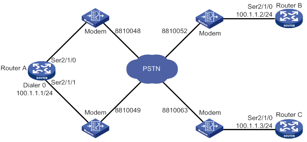
Configuration procedure
1. Configure Router A:
# Create dialer group 1 and configure a dial rule for it.
<RouterA> system-view
[RouterA] dialer-group 1 rule ip permit
# Enable traditional DDR on Dialer 0.
[RouterA] interface dialer 0
[RouterA-Dialer0] dialer circular enable
# Configure an IP address for the interface.
[RouterA-Dialer0] ip address 100.1.1.1 255.255.255.0
# Associate dialer group 1 with the interface.
[RouterA-Dialer0] dialer-group 1
# Configure dial strings for calling Router B and Router C.
[RouterA-Dialer0] dialer route ip 100.1.1.2 dial-number 8810052
[RouterA-Dialer0] dialer route ip 100.1.1.3 dial-number 8810063
[RouterA-Dialer0] quit
# Configure Serial 2/1/0 to operate as an asynchronous interface in protocol mode.
[RouterA] interface serial 2/1/0
[RouterA-Serial2/1/0] physical-mode async
[RouterA-Serial2/1/0] async-mode protocol
# Assign the interface to dialer circular group 0.
[RouterA-Serial2/1/0] dialer circular-group 0
[RouterA-Serial2/1/0] quit
# Configure Serial 2/1/1 to operate as an asynchronous interface in protocol mode.
[RouterA] interface serial 2/1/1
[RouterA-Serial2/1/1] physical-mode async
[RouterA-Serial2/1/1] async-mode protocol
# Assign the interface to dialer circular group 0.
[RouterA-Serial2/1/1] dialer circular-group 0
[RouterA-Serial2/1/1] quit
# Configure user lines to be used, and enable modem dial-in and dial-out on them.
[RouterA] line tty1
[RouterA-line-tty1] modem enable both
[RouterA-line-tty1] quit
[RouterA] line tty2
[RouterA-line-tty2] modem enable both
2. Configure Router B:
# Create dialer group 1 and configure a dial rule for it.
<RouterB> system-view
[RouterB] dialer-group 1 rule ip permit
# Configure Serial 2/1/0 to operate as an asynchronous interface in protocol mode.
[RouterB] interface serial 2/1/0
[RouterB-Serial2/1/0] physical-mode async
[RouterB-Serial2/1/0] async-mode protocol
# Configure an IP address for the interface.
[RouterB-Serial2/1/0] ip address 100.1.1.2 255.255.255.0
# Enable traditional DDR on the interface.
[RouterB-Serial2/1/0] dialer circular enable
# Associate dialer group 1 with the interface.
[RouterB-Serial2/1/0] dialer-group 1
# Configure the dial strings for calling Router A.
[RouterB-Serial2/1/0] dialer route ip 100.1.1.1 dial-number 8810048
[RouterB-Serial2/1/0] dialer route ip 100.1.1.1 dial-number 8810049
[RouterB-Serial2/1/0] quit
# Configure the user line to be used, and enable modem dial-in and dial-out on it.
[RouterB] line tty1
[RouterB-line-tty1] modem enable both
3. Configure Router C:
# Create dialer group 1 and configure a dial rule for it.
<RouterC> system-view
[RouterC] dialer-group 1 rule ip permit
# Configure Serial 2/1/0 to operate as an asynchronous interface in protocol mode.
[RouterC] interface serial 2/1/0
[RouterC-Serial2/1/0] physical-mode async
[RouterC-Serial2/1/0] async-mode protocol
# Configure an IP address for the interface.
[RouterC-Serial2/1/0] ip address 100.1.1.3 255.255.255.0
# Enable traditional DDR on the interface.
[RouterC-Serial2/1/0] dialer circular enable
# Associate dialer group 1 with the interface.
[RouterC-Serial2/1/0] dialer-group 1
# Configure two dial strings for calling Router A.
[RouterC-Serial2/1/0] dialer route ip 100.1.1.1 dial-number 8810048
[RouterC-Serial2/1/0] dialer route ip 100.1.1.1 dial-number 8810049
[RouterC-Serial2/1/0] quit
# Configure the user line to be used, and enable modem dial-in and dial-out on it.
[RouterC] line tty1
[RouterC-line-tty1] modem enable both
Verifying the configuration
# Verify that Router A can successfully ping Router B and Router C. (Details not shown.)
# Verify that Router B and Router C cannot ping each other. (Details not shown.)
PSTN-based bundle DDR configuration example
Network requirements
As shown in Figure 56:
· Dialer0 interfaces of Router A and Router B are in the same network segment.
· Dialer1 interface of Router A and the Dialer0 interface of Router C are in the same network segment.
Configure bundle DDR to meet the following requirements:
· Router A can call Router B and Router C from multiple interfaces.
· Router B and Router C cannot each other.
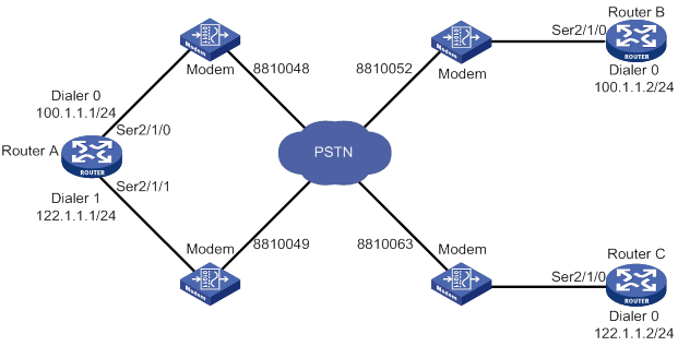
Configuration procedure
1. Configure Router A:
# Create dialer group 1 and configure a dial rule for it.
<RouterA> system-view
[RouterA] dialer-group 1 rule ip permit
# Create local users userb and userc for authenticating Router B and Router C, and configure the service type as PPP for them.
[RouterA] local-user userb class network
[RouterA-luser-network-userb] password simple userb
[RouterA-luser-network-userb] service-type ppp
[RouterA-luser-network-userb] quit
[RouterA] local-user userc class network
[RouterA-luser-network-userc] password simple userc
[RouterA-luser-network-userc] service-type ppp
[RouterA-luser-network-userc] quit
# Configure an IP address for Dialer 0.
[RouterA] interface dialer 0
[RouterA-Dialer0] ip address 100.1.1.1 255.255.255.0
# Enable bundle DDR on the interface.
[RouterA-Dialer0] dialer bundle enable
# Specify the host name of the remote router allowed to call in.
[RouterA-Dialer0] dialer peer-name userb
# Associate the interface with dialer group 1.
[RouterA-Dialer0] dialer-group 1
# Configure PAP authentication on the interface.
[RouterA-Dialer0] ppp authentication-mode pap
[RouterA-Dialer0] ppp pap local-user usera password simple usera
# Configure the dial string for calling Router B.
[RouterA-Dialer0] dialer number 8810052
[RouterA-Dialer0] quit
# Configure an IP address for Dialer 1.
[RouterA] interface dialer 1
[RouterA-Dialer1] ip address 122.1.1.1 255.255.255.0
# Enable bundle DDR on the interface.
[RouterA-Dialer1] dialer bundle enable
# Specify the host name of the remote router allowed to call in.
[RouterA-Dialer1] dialer peer-name userc
# Associate the interface with dialer group 1.
[RouterA-Dialer1] dialer-group 1
# Configure PAP authentication on the interface.
[RouterA-Dialer1] ppp authentication-mode pap
[RouterA-Dialer1] ppp pap local-user usera password simple usera
# Configure the dial string for calling Router C.
[RouterA-Dialer1] dialer number 8810063
[RouterA-Dialer1] quit
# Configure Serial 2/1/0 as an asynchronous interface in protocol mode.
[RouterA] interface serial 2/1/0
[RouterA-Serial2/1/0] physical-mode async
[RouterA-Serial2/1/0] async-mode protocol
# Assign the interface to Dialer 0 and Dialer 1.
[RouterA-Serial2/1/0] dialer bundle-member 0
[RouterA-Serial2/1/0] dialer bundle-member 1
# Enable PPP encapsulation on the interface.
[RouterA-Serial2/1/0] link-protocol ppp
# Configure PAP authentication on the interface.
[RouterA-Serial2/1/0] ppp authentication-mode pap
[RouterA-Serial2/1/0] ppp pap local-user usera password simple usera
[RouterA-Serial2/1/0] quit
# Configure Serial 2/1/1 as an asynchronous interface in protocol mode.
[RouterA] interface serial 2/1/1
[RouterA-Serial2/1/1] physical-mode async
[RouterA-Serial2/1/1] async-mode protocol
# Assign the interface to Dialer 0 and Dialer 1.
[RouterA-Serial2/1/1] dialer bundle-member 0
[RouterA-Serial2/1/1] dialer bundle-member 1
# Enable PPP encapsulation on the interface.
[RouterA-Serial2/1/1] link-protocol ppp
# Configure PAP authentication on the interface.
[RouterA-Serial2/1/1] ppp authentication-mode pap
[RouterA-Serial2/1/1] ppp pap local-user usera password simple usera
[RouterA-Serial2/1/1] quit
# Configure user lines to be used, and enable modem dial-in and dial-out on them.
[RouterA] line tty1
[RouterA-line-tty1] modem enable both
[RouterA-line-tty1] quit
[RouterA] line tty2
[RouterA-line-tty2] modem enable both
2. Configure Router B:
# Create dialer group 2 and configure a dial rule for it.
<RouterB> system-view
[RouterB] dialer-group 2 rule ip permit
# Create a local user usera for authenticating Router A, and configure the service type as PPP.
[RouterB] local-user usera class network
[RouterB-luser-network-usera] password simple usera
[RouterB-luser-network-usera] service-type ppp
[RouterB-luser-network-usera] quit
# Configure an IP address for Dialer 0.
[RouterB] interface dialer 0
[RouterB-Dialer0] ip address 100.1.1.2 255.255.255.0
# Enable bundle DDR on the interface.
[RouterB-Dialer0] dialer bundle enable
# Specify the host name of the remote router allowed to call in.
[RouterB-Dialer0] dialer peer-name usera
# Configure the dial string for calling Serial 2/1/0 on Router A.
[RouterB-Dialer0] dialer number 8810048
# Associate the interface with dialer group 2.
[RouterB-Dialer0] dialer-group 2
# Configure PAP authentication on the interface.
[RouterB-Dialer0] ppp authentication-mode pap
[RouterB-Dialer0] ppp pap local-user userb password simple userb
[RouterB-Dialer0] quit
# Configure Serial 2/1/0 as an asynchronous interface in protocol mode.
[RouterB] interface serial 2/1/0
[RouterB-Serial2/1/0] physical-mode async
[RouterB-Serial2/1/0] async-mode protocol
# Assign the interface to Dialer 0.
[RouterB-Serial2/1/0] dialer bundle-member 0
# Enable PPP encapsulation on the interface.
[RouterB-Serial2/1/0] link-protocol ppp
# Configure PAP authentication on the interface.
[RouterB-Serial2/1/0] ppp authentication-mode pap
[RouterB-Serial2/1/0] ppp pap local-user userb password simple userb
[RouterB-Serial2/1/0] quit
# Configure the user line to be used, and enable modem dial-in and dial-out on it.
[RouterB] line tty1
[RouterB-line-tty1] modem enable both
3. Configure Router C:
# Create dialer group 1 and configure a dial rule for it.
<RouterC> system-view
[RouterC] dialer-group 1 rule ip permit
# Create a local user usera for authenticating Router A, and configure the service type as PPP.
[RouterC] local-user usera class network
[RouterC-luser-network-usera] password simple usera
[RouterC-luser-network-usera] service-type ppp
[RouterC-luser-network-usera] quit
# Configure an IP address for Dialer 0.
[RouterC] interface dialer 0
[RouterC-Dialer0] ip address 122.1.1.2 255.255.255.0
# Enable bundle DDR on the interface.
[RouterC-Dialer0] dialer bundle enable
# Configure the Specify the host name of the remote router allowed to call in.
[RouterC-Dialer0] dialer peer-name usera
# Configure the dial string for calling Serial 2/1/1 on Router A.
[RouterC-Dialer0] dialer number 8810049
# Associate the interface with dialer group 1.
[RouterC-Dialer0] dialer-group 1
# Configure PAP authentication on the interface.
[RouterC-Dialer0] ppp authentication-mode pap
[RouterC-Dialer0] ppp pap local-user userc password simple userc
[RouterC-Dialer0] quit
# Configure Serial 2/1/0 as an asynchronous interface in protocol mode.
[RouterC] interface serial 2/1/0
[RouterC-Serial2/1/0] physical-mode async
[RouterC-Serial2/1/0] async-mode protocol
# Assign the interface to Dialer 0.
[RouterC-Serial2/1/0] dialer bundle-member 0
# Enable PPP encapsulation on the interface.
[RouterC-Serial2/1/0] link-protocol ppp
# Configure PAP authentication on the interface.
[RouterC-Serial2/1/0] ppp authentication-mode pap
[RouterC-Serial2/1/0] ppp pap local-user userc password simple userc
[RouterC-Serial2/1/0] quit
# Configure the user line to be used, and enable modem dial-in and dial-out on it.
[RouterC] line tty1
[RouterC-line-tty1] modem enable both
Verifying the configuration
# Verify that Router A can successfully ping Router B and Router C. (Details not shown.)
# Verify that Router B and Router C cannot ping each other. (Details not shown.)
ISDN-based traditional DDR configuration example
Network requirements
As shown in Figure 57, the interfaces BRI 2/4/0 of Router A, Router B, and Router C are in the same network segment.
Configure traditional DDR to meet the following requirements:
· Allow Router A to call Router B and Router C from multiple interfaces.
· Disable Router B and Router C from calling each other.
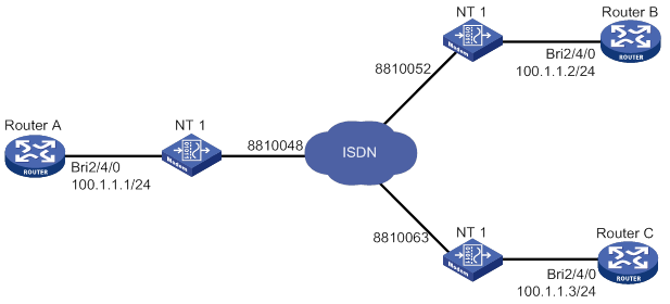
Configuration procedure
1. Configure Router A:
# Create dialer group 1 and configure a dial rule for it.
<RouterA> system-view
[RouterA] dialer-group 1 rule ip permit
# Configure an IP address for interface BRI 2/4/0.
[RouterA] interface bri 2/4/0
[RouterA-Bri2/4/0] ip address 100.1.1.1 255.255.255.0
# Enable traditional DDR on the interface.
[RouterA-Bri2/4/0] dialer circular enable
# Associate the interface with dialer group 1.
[RouterA-Bri2/4/0] dialer-group 1
# Configure the dial strings for calling Router B and Router C.
[RouterA-Bri2/4/0] dialer route ip 100.1.1.2 dial-number 8810052
[RouterA-Bri2/4/0] dialer route ip 100.1.1.3 dial-number 8810063
2. Configure Router B:
# Create dialer group 2 and configure a dial rule for it.
<RouterB> system-view
[RouterB] dialer-group 2 rule ip permit
# Configure an IP address for interface BRI 2/4/0.
[RouterB] interface bri 2/4/0
[RouterB-Bri2/4/0] ip address 100.1.1.2 255.255.255.0
# Enable traditional DDR on the interface.
[RouterB-Bri2/4/0] dialer circular enable
# Associate the interface with dialer group 2.
[RouterB-Bri2/4/0] dialer-group 2
# Configure the dial string for calling Router A.
[RouterB-Bri2/4/0] dialer route ip 100.1.1.1 dial-number 8810048
3. Configure Router C:
# Create dialer group 1 and configure a dial rule for it.
<RouterC> system-view
[RouterC] dialer-group 1 rule ip permit
# Configure an IP address for interface BRI 2/4/0.
[RouterC] interface bri 2/4/0
[RouterC-Bri2/4/0] ip address 100.1.1.3 255.255.255.0
# Enable traditional DDR on the interface.
[RouterC-Bri2/4/0] dialer circular enable
# Associate the interface with dialer group 1.
[RouterC-Bri2/4/0] dialer-group 1
# Configure the dial string for calling Router A.
[RouterC-Bri2/4/0] dialer route ip 100.1.1.1 dial-number 8810048
Verifying the configuration
# Verify that Router A can successfully ping Router B and Router C. (Details not shown.)
# Verify that Router B and Router C cannot ping each other. (Details not shown.)
ISDN-based bundle DDR configuration example
Network requirements
As shown in Figure 58, the interfaces BRI 2/4/0 of Router A, Router B, and Router C are in the same network segment.
Configure bundle DDR to meet the following requirements:
· Allow Router A to call Router B and Router C from multiple interfaces.
· Disable Router B and Router C from calling each other.
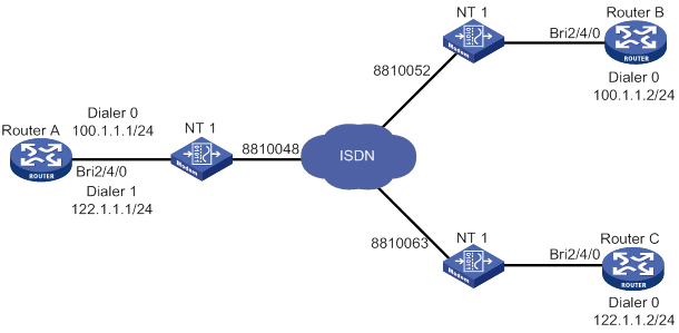
Configuration procedure
1. Configure Router A:
# Create dialer group 1 and configure a dial rule for it.
<RouterA> system-view
[RouterA] dialer-group 1 rule ip permit
# Create local users userb and userc for authenticating Router B and Router C, and configure the service type as PPP for them.
[RouterA] local-user userb class network
[RouterA-luser-network-userb] password simple userb
[RouterA-luser-network-userb] service-type ppp
[RouterA-luser-network-userb] quit
[RouterA] local-user userc class network
[RouterA-luser-network-userc] password simple userc
[RouterA-luser-network-userc] service-type ppp
[RouterA-luser-network-userc] quit
# Configure an IP address for Dialer 0.
[RouterA] interface dialer 0
[RouterA-Dialer0] ip address 100.1.1.1 255.255.255.0
# Enable bundle DDR on the interface.
[RouterA-Dialer0] dialer bundle enable
# Specify the host name of the remote router allowed to call in.
[RouterA-Dialer0] dialer peer-name userb
# Associate the interface with dialer group 1.
[RouterA-Dialer0] dialer-group 1
# Configure PAP authentication on the interface.
[RouterA-Dialer0] ppp authentication-mode pap
[RouterA-Dialer0] ppp pap local-user usera password simple usera
# Configure the dial string for calling Router B.
[RouterA-Dialer0] dialer number 8810052
[RouterA-Dialer0] quit
# Configure an IP address for Dialer 1.
[RouterA] interface dialer 1
[RouterA-Dialer1] ip address 122.1.1.1 255.255.255.0
# Enable bundle DDR on the interface.
[RouterA-Dialer1] dialer bundle enable
# Specify the host name of the remote router allowed to call in.
[RouterA-Dialer1] dialer peer-name userc
# Associate the interface with dialer group 1.
[RouterA-Dialer1] dialer-group 1
# Configure PAP authentication on the interface.
[RouterA-Dialer1] ppp authentication-mode pap
[RouterA-Dialer1] ppp pap local-user usera password simple usera
# Configure the dial string for calling Router C.
[RouterA-Dialer1] dialer number 8810063
[RouterA-Dialer1] quit
# Assign interface BRI 2/4/0 to dialer bundle 0 and dialer bundle 1.
[RouterA] interface bri 2/4/0
[RouterA-Bri2/4/0] dialer bundle-member 0
[RouterA-Bri2/4/0] dialer bundle-member 1
# Configure PAP authentication on the interface.
[RouterA-Bri2/4/0] ppp authentication-mode pap
[RouterA-Bri2/4/0] ppp pap local-user usera password simple usera
2. Configure Router B:
# Create dialer group 2 and configure a dial rule for it.
<RouterB> system-view
[RouterB] dialer-group 2 rule ip permit
# Create a local user usera for authenticating Router A, and configure the service type as PPP.
[RouterB] local-user usera class network
[RouterB-luser-network-usera] password simple usera
[RouterB-luser-network-usera] service-type ppp
[RouterB-luser-network-usera] quit
# Configure an IP address for Dialer 0.
[RouterB] interface dialer 0
[RouterB-Dialer0] ip address 100.1.1.2 255.255.255.0
# Enable bundle DDR on the interface.
[RouterB-Dialer0] dialer bundle enable
# Specify the host name of the remote router allowed to call in.
[RouterB-Dialer0] dialer peer-name usera
# Associate the interface with dialer group 2.
[RouterB-Dialer0] dialer-group 2
# Configure PAP authentication on the interface.
[RouterB-Dialer0] ppp authentication-mode pap
[RouterB-Dialer0] ppp pap local-user userb password simple userb
# Configure the dial string for calling Router A.
[RouterB-Dialer0] dialer number 8810048
[RouterB-Dialer0] quit
# Assign interface BRI 2/4/0 to dialer bundle 0.
[RouterB] interface bri 2/4/0
[RouterB-Bri2/4/0] dialer bundle-member 0
# Configure PAP authentication on the interface.
[RouterB-Bri2/4/0] ppp authentication-mode pap
[RouterB-Bri2/4/0] ppp pap local-user userb password simple userb
3. Configure Router C:
# Create dialer group 1 and configure a dial rule for it.
<RouterC> system-view
[RouterC] dialer-group 1 rule ip permit
# Create a local user usera for authenticating Router A, and configure the service type as PPP.
[RouterC] local-user usera class network
[RouterC-luser-network-usera] password simple usera
[RouterC-luser-network-usera] service-type ppp
[RouterC-luser-network-usera] quit
# Configure an IP address for Dialer 0.
[RouterC] interface dialer 0
[RouterC-Dialer0] ip address 122.1.1.2 255.255.255.0
# Enable bundle DDR on the interface.
[RouterC-Dialer0] dialer bundle enable
# Specify the host name of the remote router allowed to call in.
[RouterC-Dialer0] dialer peer-name usera
# Associate the interface with dialer group 1.
[RouterC-Dialer0] dialer-group 1
# Configure the dial string for calling Router A.
[RouterC-Dialer0] dialer number 8810048
# Configure PAP authentication on the interface.
[RouterC-Dialer0] ppp authentication-mode pap
[RouterC-Dialer0] ppp pap local-user userc password simple userc
[RouterC-Dialer0] quit
# Assign the interface to dialer bundle 0.
[RouterC] interface bri 2/4/0
[RouterC-Bri2/4/0] dialer bundle-member 0
# Configure PAP authentication on the interface.
[RouterC-Bri2/4/0] ppp authentication-mode pap
[RouterC-Bri2/4/0] ppp pap local-user userc password simple userc
Verifying the configuration
# Verify that Router A can successfully ping Router B and Router C. (Details not shown.)
# Verify that Router B and Router C cannot ping each other. (Details not shown.)
MP for DDR configuration example
Network requirements
As shown in Figure 59, two ISDN BRI interfaces on Router A and an ISDN PRI interface on Router B are connected across ISDN.
Configure Router A to call Router B by using bundle DDR, and configure Router B to call Router A by using traditional DDR. In addition, implement traffic distribution for the two interfaces on Router A by setting traffic thresholds.
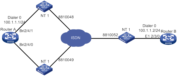
Configuration procedure
# Create dialer group 1 and configure a dial rule for it.
<RouterA> system-view
[RouterA] dialer-group 1 rule ip permit
# Create a local user userb for authenticating Router B, and configure the service type as PPP.
[RouterA] local-user userb class network
[RouterA-luser-network-userb] password simple userb
[RouterA-luser-network-userb] service-type ppp
[RouterA-luser-network-userb] quit
# Set the traffic statistics collection interval to 3 seconds.
[RouterA] dialer flow-interval 3
# Configure an IP address for Dialer 0, enable bundle DDR, and configure MP.
[RouterA] interface dialer 0
[RouterA-Dialer0] ip address 100.1.1.1 255.255.255.0
[RouterA-Dialer0] dialer bundle enable
[RouterA-Dialer0] ppp mp
[RouterA-Dialer0] dialer threshold 50
# Specify the host name of the remote router allowed to call in.
[RouterA-Dialer0] dialer peer-name userb
# Associate the interface with dialer group 1.
[RouterA-Dialer0] dialer-group 1
# Configure PAP authentication on the interface.
[RouterA-Dialer0] ppp authentication-mode pap
[RouterA-Dialer0] ppp pap local-user usera password simple usera
# Configure the dial string for calling Router B.
[RouterA-Dialer0] dialer number 8810052
[RouterA-Dialer0] quit
# Assign BRI 2/4/1 to dialer bundle 0.
[RouterA] interface bri 1/1
[RouterA-Bri2/4/1] dialer bundle-member 0
# Enable MP for the interface.
[RouterA-Bri2/4/1] ppp mp
# Configure PAP authentication on the interface.
[RouterA-Bri2/4/1] ppp authentication-mode pap
[RouterA-Bri2/4/1] ppp pap local-user usera password simple usera
[RouterA-Bri2/4/1] quit
# Configure PPP authentication on BRI 2/4/0, and assign BRI 2/4/0 to dialer bundle 0.
[RouterA-Bri2/4/0] interface bri 2/4/0
[RouterA-Bri2/4/0] dialer bundle-member 0
# Enable MP for the interface.
[RouterA-Bri2/4/0] ppp mp
# Configure PAP authentication on the interface.
[RouterA-Bri2/4/0] ppp authentication-mode pap
[RouterA-Bri2/4/0] ppp pap local-user usera password simple usera
# Create dialer group 2 and configure a dial rule for it.
<RouterB> system-view
[RouterB] dialer-group 2 rule ip permit
# Create a local user usera for authenticating Router A, and configure the service type as PPP.
[RouterB] local-user usera class network
[RouterB-luser-network-usera] password simple usera
[RouterB-luser-network-usera] service-type ppp
[RouterB-luser-network-usera] quit
# Set the traffic statistics collection interval to 3 seconds.
[RouterB] dialer flow-interval 3
# Configure an IP address for Dialer 0.
[RouterB] interface dialer 0
[RouterB-Dialer0] ip address 100.1.1.2 255.255.255.0
# Enable traditional DDR on the interface.
[RouterB-Dialer0] dialer circular enable
# Associate the interface with dialer group 2.
[RouterB-Dialer0] dialer-group 2
#Configure the dial strings for calling Router A.
[RouterB-Dialer0] dialer route ip 100.1.1.1 dial-number 8810048
[RouterB-Dialer0] dialer route ip 100.1.1.1 dial-number 8810049
# Enable MP for the interface.
[RouterB-Dialer0] ppp mp
# Configure PAP authentication on the interface.
[RouterB-Dialer0] ppp authentication-mode pap
[RouterB-Dialer0] ppp pap local-user userb password simple userb
[RouterB-Dialer0] quit
# Bundle timeslots on CE1/PRI interface E1 2/3/0 into a PRI group.
[RouterB] controller e1 2/3/0
[RouterB-E1 2/3/0] pri-set
[RouterB-E1-2/3/0] quit
# Assign Serial 2/3/0:15 created on E1 2/3/0 to dialer circular group 0, which is associated with Dialer 0.
[RouterB] interface serial 2/3/0:15
[RouterB-Serial2/3/0:15] PPP mp
[RouterB-Serial2/3/0:15] ppp authentication pap
[RouterB-Serial2/3/0:15] ppp pap local-user userb password simple userb
[RouterB-Serial2/3/0:15] dialer circular-group 0
ISDN caller number callback configuration example
Network requirements
As shown in Figure 60, configure ISDN caller number callback on Router A and Router B by using traditional DDR. Then, Router B can make a return call by using an ISDN caller number when Router A calls Router B.
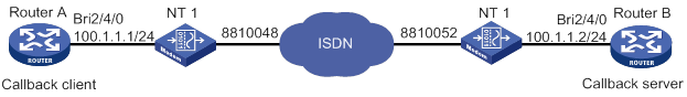
|
|
NOTE: Make sure the stored program controlled switch (SPCS) in the ISDN network supports sending ISDN calling numbers. |
Configuration procedure
1. Configure Router A:
# Create dialer group 1 and configure a dial rule for it.
<RouterA> system-view
[RouterA] dialer-group 1 rule ip permit
# Configure an IP address for interface BRI 2/4/0.
[RouterA] interface bri 2/4/0
[RouterA-Bri2/4/0] ip address 100.1.1.1 255.255.255.0
# Enable traditional DDR on the interface.
[RouterA-Bri2/4/0] dialer circular enable
# Associate the interface with dialer group 1.
[RouterA-Bri2/4/0] dialer-group 1
# Configure the dial string for calling Router B.
[RouterA-Bri2/4/0] dialer route ip 100.1.1.2 dial-number 8810052
# Set the holddown timer to 15 seconds.
[RouterA-Bri2/4/0] dialer timer enable 15
# Configure BRI 2/4/0 to carry ISDN calling number 8810048 in the message sent to the called party.
[RouterA-Bri2/4/0] isdn calling 8810048
2. Configure Router B:
# Create dialer group 2 and configure a dial rule for it.
<RouterB> system-view
[RouterB] dialer-group 2 rule ip permit
# Configure an IP address to interface BRI 2/4/0.
[RouterB] interface bri 2/4/0
[RouterB-Bri2/4/0] ip address 100.1.1.2 255.255.255.0
# Enable traditional DDR on the interface.
[RouterB-Bri2/4/0] dialer circular enable
# Associate the interface with dialer group 2.
[RouterB-Bri2/4/0] dialer-group 2
# Configure the dial string for calling Router A.
[RouterB-Bri2/4/0] dialer route ip 100.1.1.1 dial-number 8810048
# Enable the interface to place return calls for ISDN calling number 8810048.
[RouterB-Bri2/4/0] dialer call-in 8810048 callback
Router-to-router PPP callback configuration example
Network requirements
As shown in Figure 61, configure PPP callback for traditional DDR, so that when Router A calls Router B, Router B can make a return call.
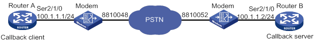
Configuration procedure
Method 1: Use the dial string configured in the dialer route command to call back the client.
1. Configure Router A:
# Create dialer group 1 and configure a dial rule for it.
<RouterA> system-view
[RouterA] dialer-group 1 rule ip permit
# Configure an IP address for Serial 2/1/0.
[RouterA] interface serial 2/1/0
[RouterA-Serial2/1/0] ip address 100.1.1.1 255.255.255.0
# Configure the interface as an asynchronous interface in protocol mode.
[RouterA-Serial2/1/0] physical-mode async
[RouterA-Serial2/1/0] async-mode protocol
# Enable traditional DDR on the interface.
[RouterA-Serial2/1/0] dialer circular enable
# Associate the interface with dialer group 1.
[RouterA-Serial2/1/0] dialer-group 1
# Configure the dial string for calling Router B.
[RouterA-Serial2/1/0] dialer route ip 100.1.1.2 dial-number 8810052
# Enable PPP encapsulation on the interface.
[RouterA-Serial2/1/0] link-protocol ppp
# Configure PAP authentication on the interface.
[RouterA-Serial2/1/0] ppp pap local-user usera password simple usera
# Enable the interface to initiate callback requests as the callback client.
[RouterA-Serial2/1/0] ppp callback client
# Set the holddown timer to 15 seconds.
[RouterA-Serial2/1/0] dialer timer enable 15
[RouterA-Serial2/1/0] quit
# Configure the user line to be used, and enable modem dial-in and dial-out on it.
[RouterA-line-tty1] modem enable both
2. Configure Router B:
# Create dialer group 2 and configure a dial rule for it.
[RouterB] dialer-group 2 rule ip permit
# Create a local user usera for authenticating Router A, and configure the service type as PPP.
[RouterB] local-user usera class network
[RouterB-luser-network-usera] password simple usera
[RouterB-luser-network-usera] service-type ppp
[RouterB-luser-network-usera] quit
# Configure an IP address for Serial 2/1/0.
[RouterB] interface serial 2/1/0
[RouterB-Serial2/1/0] ip address 100.1.1.2 255.255.255.0
# Configure the interface as an asynchronous interface in protocol mode.
[RouterB-Serial2/1/0] physical-mode async
[RouterB-Serial2/1/0] async-mode protocol
# Enable traditional DDR on the interface.
[RouterB-Serial2/1/0] dialer circular enable
# Associate the interface with dialer group 2.
[RouterB-Serial2/1/0] dialer-group 2
# Enable PPP encapsulation on the interface.
[RouterB-Serial2/1/0] link-protocol ppp
# Enable PAP authentication on the interface.
[RouterB-Serial2/1/0] ppp authentication-mode pap
# Enable the interface to accept callback requests as the callback server.
[RouterB-Serial2/1/0] ppp callback server
# Configure the interface to use the dial string configured in the dialer route command to call back.
[RouterB-Serial2/1/0] dialer callback-center user
# Configure the dial string for callback.
[RouterB-Serial2/1/0] dialer route ip 100.1.1.1 dial-number 8810048 user usera
[RouterB-Serial2/1/0] quit
# Configure the user line to be used, and enable modem dial-in and dial-out on it.
[RouterB-line-tty2] modem enable both
Method 2: Use the callback number configured in the authorization-attribute callback-number command to call back the client.
3. Configure Router A:
# Create dialer group 1 and configure a dial rule for it.
<RouterA> system-view
[RouterA] dialer-group 1 rule ip permit
# Configure an IP address for Serial 2/1/0.
[RouterA] interface serial 2/1/0
[RouterA-Serial2/1/0] ip address 100.1.1.1 255.255.255.0
# Configure the interface as an asynchronous interface in protocol mode.
[RouterA-Serial2/1/0] physical-mode async
[RouterA-Serial2/1/0] async-mode protocol
# Enable traditional DDR on the interface.
[RouterA-Serial2/1/0] dialer circular enable
# Associate the interface with dialer group 1.
[RouterA-Serial2/1/0] dialer-group 1
# Configure the dial string for calling Router B.
[RouterA-Serial2/1/0] dialer route ip 100.1.1.2 dial-number 8810052
# Enable PPP encapsulation on the interface.
[RouterA-Serial2/1/0] link-protocol ppp
# Configure PAP authentication on the interface.
[RouterA-Serial2/1/0] ppp pap local-user usera password simple usera
# Enable the interface to initiate callback requests as the callback client.
[RouterA-Serial2/1/0] ppp callback client
# Set the holddown timer to 15 seconds.
[RouterA-Serial2/1/0] dialer timer enable 15
[RouterA-Serial2/1/0] quit
# Configure the user line to be used, and enable modem dial-in and dial-out on it.
[RouterA] line tty1
[RouterA-line-tty1] modem enable both
4. Configure Router B:
# Create dialer group 2 and configure a dial rule for it.
[RouterB] dialer-group 2 rule ip permit
# Create a local user usera for authenticating Router A, and configure the service type as PPP.
[RouterB] local-user usera class network
[RouterB-luser-network-usera] password simple usera
[RouterB-luser-network-usera] service-type ppp
# Configure the dial string for callback.
[RouterB-luser-network-usera] authorization-attribute callback-number 8810048
[RouterB-luser-network-usera] quit
# Configure an IP address for Serial 2/1/0.
[RouterB] interface serial 2/1/0
[RouterB-Serial2/1/0] ip address 100.1.1.2 255.255.255.0
# Configure the interface as an asynchronous interface in protocol mode.
[RouterB-Serial2/1/0] physical-mode async
[RouterB-Serial2/1/0] async-mode protocol
# Enable traditional DDR on the interface.
[RouterB-Serial2/1/0] dialer circular enable
# Associate the interface with dialer group 2.
[RouterB-Serial2/1/0] dialer-group 2
# Enable PPP encapsulation on the interface.
[RouterB-Serial2/1/0] link-protocol ppp
# Enable PAP authentication on the interface.
[RouterB-Serial2/1/0] ppp authentication-mode pap
# Enable the interface to accept callback requests as the callback server.
[RouterB-Serial2/1/0] ppp callback server
# Configure the interface to use the dial string configured in the dialer callback-center dial-number command to call back.
[RouterB-Serial2/1/0] dialer callback-center dial-number
[RouterB-Serial2/1/0] quit
# Configure the user line to be used, and enable modem dial-in and dial-out on it.
[RouterB] line tty2
[RouterB-line-tty2] modem enable both
Router-to-PC PPP callback configuration example
Network requirements
As shown in Figure 62, the PC obtains its IP address from the router through PPP.
Configure PPP callback for traditional DDR between the router and the PC. Then, the router can use the specified dial string to make a return call when the PC calls the router.
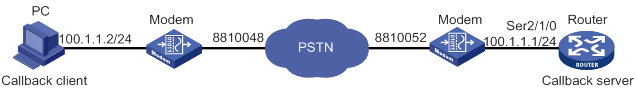
Configuring the PC (installed with Windows XP for example)
To create a dialup connection with callback capability enabled:
1. Place the modem connected to PC in auto answer mode.
2. Select Start > Programs > Accessories > Communications > Network and Dial-up Connections.
The Network and Dial-up Connections window appears.
3. Right-click the Make New Connection icon, and select New Connection… from the shortcut menu.
The Network Connection Wizard window appears.
4. Click Next.
The Network Connection Type dialog box appears.
5. Select the Dial-up to the Internet option, and click Next.
The Internet Connection Wizard dialog appears.
6. Select I want to set up my Internet connection manually or I want to connect through a local area network. Click Next.
The Setting up your Internet connection dialog box appears.
7. Select the I connect through a phone line and a modem option, and click Next.
8. Enter the phone number for dialing to the callback server, and click Next.
9. Enter the username and password that you want to use for PPP authentication when connecting to the server, and click Next.
10. Assign a name to your new connection and follow the instruction to complete the connection establishment.
11. Open the Network and Dial-up Connections window, right-click the connection you created, and select the Properties option in the popup menu.
The properties setting dialog box appears.
12. Click the Networking tab. On the Type of dial-up server I am calling list, select PPP: Windows 95/98/NT4/2000, Internet. Click Settings and perform the following tasks:
a. Select the Enable LCP extensions box.
b. Clear the Enable software compression box.
c. Clear the Negotiate multi-link for single link connections box.
d. Click OK.
13. In the Network and Dial-up Connections window, click the connection icon you created. Then, from the menu bar, select Advanced > Dial-up Preferences. In the Dial-up Preferences dialog box, click the Callback tab and perform one of the following tasks:
? Select the No callback option.
After the PPP authentication is passed in a call, this option prevents the callback server from disconnecting the current connection and calling back. Instead, the server will maintain the current connection and allow the client to access the LAN or the Internet.
? Select the Ask me during dialing when the server offers option.
The callback server will use the callback number you entered to place return calls.
? Select the Always call me back at the number(s) below option.
The callback server will always place return calls at the number or numbers already set.
Configuring the router
# Create dialer group 1 and configure a dial rule for it.
<Router> system-view
[Router] dialer-rule 1 ip permit
# Create a local user userpc for the PC, and configure the service type as PPP.
[Router] local-user userpc
[Router-luser-userpc] password simple userpc
[Router-luser-userpc] service-type ppp
[Router-luser-userpc] quit
# Configure an IP address for Serial 2/1/0.
[Router] interface serial 2/1/0
[Router-Serial2/1/0] ip address 100.1.1.1 255.255.255.0
# Configure the interface as an asynchronous interface in protocol mode.
[Router-Serial2/1/0] physical-mode async
[Router-Serial2/1/0] async mode protocol
# Enable PPP encapsulation on the interface.
[Router-Serial2/1/0] link-protocol ppp
# Configure PAP authentication on the interface.
[Router-Serial2/1/0] ppp authentication-mode pap
[Router-Serial2/1/0] ppp pap local-user Router password simple Router
# Configure the interface to assign an IP address to the peer.
[Router-Serial2/1/0] remote address 100.1.1.2
# Enable the interface to accept callback requests as the callback server.
[Router-Serial2/1/0] ppp callback server
# Configure the interface to use the dial string configured in the dialer route command to call back.
[Router-Serial2/1/0] dialer callback-center user
# Enable traditional DDR on the interface.
[Router-Serial2/1/0] dialer circular enable
# Associate the interface with dialer group 1.
[Router-Serial2/1/0] dialer-group 1
# Configure the dial string for calling the PC.
[Router-Serial2/1/0] dialer route ip 100.1.1.2 dial-number 8810048 user userpc
[Router-Serial2/1/0] quit
# Configure the user line to be used, and enable modem dial-in and dial-out on it.
[Router] line tty1
[Router-line-tty1] modem enable both
Windows server-to-router PPP callback configuration example
Network requirements
As shown in Figure 63, the router obtains its IP address from the Windows server through PPP.
Configure PPP callback for traditional DDR between the router and Windows server. Then, the Windows server can use the specified dial string to make a return call when the router calls the Windows server.
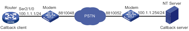
Configuring the router
# Create dialer group 1 and configure a dial rule for it.
<Router> system-view
[Router] dialer-group 1 rule ip permit
# Create a local user userpc for the PC, and configure the service type as PPP.
[Router] local-user usernt class network
[Router-luser-network-userc] password simple usernt
[Router-luser-network-userc] service-type ppp
[Router-luser-network-userc] quit
# Configure Serial 2/1/0 as an asynchronous interface in protocol mode.
[Router] interface serial 2/1/0
[Router-Serial2/1/0] physical-mode async
[Router-Serial2/1/0] async-mode protocol
# Enable PPP encapsulation on the interface.
[Router-Serial2/1/0] link-protocol ppp
# Configure PAP authentication on the interface.
[Router-Serial2/1/0] ppp authentication-mode pap
[Router-Serial2/1/0] ppp pap local-user Router password simple Router
# Configure the interface to obtain an IP address through PPP negotiation.
[Router-Serial2/1/0] ip address ppp-negotiate
# Enable the interface to initiate callback requests as the callback client.
[Router-Serial2/1/0] ppp callback client
# Set the holddown timer to 15 seconds.
[Router-Serial2/1/0] dialer timer enable 15
# Enable traditional DDR on the interface.
[Router-Serial2/1/0] dialer circular enable
# Associate the interface with dialer group 1.
[Router-Serial2/1/0] dialer-group 1
# Configure the dial string for calling the Windows server.
[Router-Serial2/1/0] dialer route ip 100.1.1.254 dial-number 8810052
[Router-Serial2/1/0] quit
# Configure the user line to be used, and enable modem dial-in and dial-out on it.
[Router] line tty1
[Router-line-tty1] modem enable both
Configuring the Windows server
For Microsoft Windows users, the server must be Windows 2000 or later such as Windows XP. This example uses Windows XP.
To create a dialup connection with callback capability enabled:
1. Right-click the My Network Places icon, and select the Properties option from the menu that appears.
The Network and Dial-up Connections window appears.
2. Right-click the Make New Connection icon, and select the New Connection…option from the menu that appears.
The Network Connection Wizard window appears.
3. Click Next.
The Network Connection Type dialog box appears.
4. Select Set up an advanced connection, and click Next.
5. Select the Accept incoming connections option, and click Next to set the devices for incoming connections. Click Next.
The Incoming Virtual Private Network (VPN) Connection window appears.
6. Select the Allow virtual private connections option if the server is connected to the Internet to provide Internet access requests for the client. Otherwise, select the Do not allow virtual private connections. Then click Next.
The User Permissions window appears. Set the usernames and passwords for the clients allowed to call back.
7. Click Add. In the New User dialog box that appears, add the username and password for the PPP callback client and click OK.
An icon for the new user account appears in the box in the User Permissions window.
8. Select the new user and click Properties.
The properties setting dialog appears.
9. On the Callback tab, perform one of the following tasks:
? Select the Do not allow callback option.
After the PPP authentication is passed in a call, this option prevents the callback server from disconnecting the current connection and calling back. Instead, the server will maintain the current connection and allow the client to access the LAN or the Internet.
? Select the Allow the caller to set the callback number option.
After the PPP authentication is passed in a call, the server will disconnect and then call back the client at the number configured in the ppp callback ntstring dial-number command. This option is the same as the last option except that the charges are paid by the server end instead of the client end.
? Select the Always use the following callback number option to set a callback number.
10. Click Next.
The Networking Software window appears.
11. Set the networking components, and use the default settings for the network protocols. Click Next.
12. Assign a name to your connection.
13. Click Finish to complete the creation.
Configuration example for circular dial string backup and Internet access
Network requirements
As shown in Figure 64:
· Router B operates as an access server and is configured with an IP address of 100.1.1.254/24. It uses the address range of 100.1.1.1/24 to 100.1.1.16/24 for address assignment. The PSTN dial strings available on it are 8810048 through 8810055, allowing the router to provide services to 16 online users.
· Router A accepts the IP address assigned by Router B.
Configure Router A on the dialup side to implement cyclic dial string backup with dialer routes. Configure Router B on the access side to use asynchronous serial interfaces to provide DDR dialup access and adopt PAP to authenticate the dialup side.
As shown in Figure 65, Router C and Router D have the same configurations as Router A and Router B. The only difference is that Router D uses an ISDN dial string 8810048 rather than PSTN dial strings to provide services.
Configure Router C and Router D to implement DDR with one dial string and use CHAP for authentication.
Figure 64 Network diagram for dial string backup/Internet access service (PSTN mode)
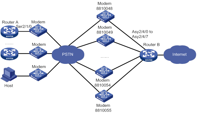
Figure 65 Network diagram for dial string backup/Internet access service (ISDN mode)
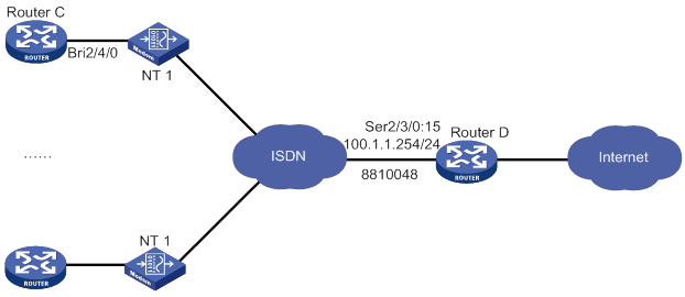
Configuration procedure for PSTN mode
On Router A on the dialup side, configure circular dial string backup.
On Router B, perform the following tasks:
· Configure traditional DDR to allow the router to establish connections on eight asynchronous serial interfaces.
· Configure traditional DDR parameters on a dialer interface.
1. Configure Router A:
# Create dialer group 1 and configure a dial rule for it.
<RouterA> system-view
[RouterA] dialer-group 1 rule ip permit
# Create a local user userb for authenticating Router B, and configure the service type as PPP.
[RouterA] local-user userb class network
[RouterA-luser-network-userb] password simple userb
[RouterA-luser-network-userb] service-type ppp
[RouterA-luser-network-userb] quit
# Configure Serial 2/1/0 as an asynchronous interface in protocol mode.
[RouterA] interface serial 2/1/0
[RouterA-Serial2/1/0] physical-mode async
[RouterA-Serial2/1/0] async-mode protocol
# Enable PPP address negotiation on the interface.
[RouterA-Serial2/1/0] ip address ppp-negotiate
# Enable PPP encapsulation on the interface.
[RouterA-Serial2/1/0] link-protocol ppp
# Configure PAP authentication on the interface.
[RouterA-Serial2/1/0] ppp authentication-mode pap
[RouterA-Serial2/1/0] ppp pap local-user user1 password simple user1
# Enable traditional DDR on the interface.
[RouterA-Serial2/1/0] dialer circular enable
# Associate the interface with dialer group 1.
[RouterA-Serial2/1/0] dialer-group 1
# Configure the dial strings for calling Router B.
[RouterA-Serial2/1/0] dialer route ip 100.1.1.254 dial-number 8810048
[RouterA-Serial2/1/0] dialer route ip 100.1.1.254 dial-number 8810049
...
[RouterA-Serial2/1/0] dialer route ip 100.1.1.254 dial-number 8810055
[RouterA-Serial2/1/0] quit
# Configure the user line to be used, and enable modem dial-in and dial-out on it.
[RouterA] line tty1
[RouterA-line-tty1] modem enable both
2. Configure Router B:
# Create dialer group 2 and configure a dial rule for it.
<RouterB> system-view
[RouterB] dialer-group 2 rule ip permit
# Create local users user1 through user16 for authentication, and configure the service type as PPP for them.
[RouterB] local-user user1 class network
[RouterB-luser-network-user1] password simple user1
[RouterB-luser-network-user1] service-type ppp
[RouterB-luser-network-user1] quit
[RouterB] local-user user2 class network
[RouterB-luser-network-user2] password simple user2
[RouterB-luser-network-user2] service-type ppp
[RouterB-luser-network-user2] quit
...
[RouterB] local-user user16 class network
[RouterB-luser-network-user16] password simple user16
[RouterB-luser-network-user16] service-type ppp
[RouterB-luser-network-user16] quit
# Enable PPP encapsulation on Dialer 0.
[RouterB] interface dialer 0
[RouterB-Dialer0] link-protocol ppp
# Configure PAP authentication on the interface.
[RouterB-Dialer0] ppp authentication-mode pap
[RouterB-Dialer0] ppp pap local-user userb password simple userb
# Configure an IP address for the interface.
[RouterB-Dialer0] ip address 100.1.1.254 255.255.255.0
# Configure the interface to assign IP addresses to PPP users.
[RouterB-Dialer0] remote address pool 1
# Configure traditional DDR on the interface.
[RouterB-Dialer0] dialer circular enable
# Associate the interface with dialer group 2.
[RouterB-Dialer0] dialer-group 2
[RouterB-Dialer0] quit
# Configure Async 2/4/0 to operate in protocol mode.
[RouterB] interface async 2/4/0
[RouterB-Async2/4/0] async-mode protocol
# Assign the interface to dialer circular group 0.
[RouterB-Async2/4/0] dialer circular-group 0
# Enable PPP encapsulation on the interface.
[RouterB-Async2/4/0] link-protocol ppp
# Configure PAP authentication on the interface.
[RouterB-Async2/4/0] ppp authentication-mode pap
[RouterB-Async2/4/0] ppp pap local-user userb password simple userb
[RouterB-Async2/4/0] quit
# Repeat the steps to configure physical and link layer parameters for interfaces Async 2/4/1 through Async 2/4/7. (Details not shown.)
# Configure user lines TTY 1 through TTY 7 for interfaces Async 2/4/0 through Async 2/4/7, and enable modem dial-in and dial-out on them.
[RouterB] line tty1
[RouterB-line-tty1] modem enable both
[RouterB-line-tty1] quit
[RouterB] line tty2
[RouterB-line-tty2] modem enable both
...
[RouterB-line-tty8] quit
# Configure an IP address pool for address assignment.
[RouterB] domain system
[RouterB-isp-system] ip pool 1 100.1.1.1 100.1.1.16
[RouterB-isp-system] quit
3. Configure the PC:
a. Place the modem connected to PC in auto answer mode.
b. Right-click the My Network Places icon and select the Properties option from the menu that appears.
The Network and Dial-up Connections window appears.
c. Right-click the Make New Connection icon and select the New Connection…option from the menu that appears.
The Network Connection Wizard window appears.
d. Click Next.
The Network Connection Type dialog box appears.
e. Select the Dial-up to the Internet option, and click Next.
The Internet Connection Wizard dialog appears.
f. Select I want to set up my Internet connection manually, or I want to connect through a local area network. Click Next.
The Setting up your Internet connection dialog box appears.
g. Select the I connect through a phone line and a modem option. Click Next.
h. Enter the phone number for dialing to the callback server. Click Next.
i. Enter the username user16 and password user16 that you want to use for PPP authentication when connecting to the server. Click Next.
j. Assign a name to your new connection and follow the instruction to complete the connection establishment.
k. Open the Network and Dial-up Connections window, right-click the connection you just created, and select the Properties option in the menu that appears.
The properties setting dialog box appears.
l. Select the Networking tab. In the Type of dial-up server I am calling list, select PPP: Windows 95/98/NT4/2000, Internet. Click Settings, select the Enable LCP extensions box, clear the Enable software compression box, clear the Negotiate multi-link for single link connections box, and click OK.
m. Turn to the Network and Dial-up Connections window. Click the connection icon you just created. Then, from the menu bar, select Advanced > Dial-up Preferences. In the Dial-up Preferences dialog box, select the Callback tab and select the No callback option.
n. Double-click the created connection to dial.
Configuration procedure for ISDN mode
On Router C on the dialup side, configure a single dial string.
On Router D on the access side, perform the following tasks:
· Use traditional DDR to establish a connection with Router C through an ISDN PRI interface.
· Configure DDR parameters on a dialer interface.
1. Configure Router C:
# Create dialer group 1 and configure a dial rule for it.
<RouterC> system-view
[RouterC] dialer-group 1 rule ip permit
# Create a local user user1 for authentication, and configure the service type as PPP.
[RouterC] local-user userd class network
[RouterC-luser-network-userd] password simple user1
[RouterC-luser-network-userd] service-type ppp
[RouterC-luser-network-userd] quit
# Enable PPP address negotiation on BRI 2/4/0.
[RouterC] interface bri 2/4/0
[RouterC-Bri2/4/0] ip address ppp-negotiate
# Configure CHAP authentication on the interface.
[RouterC-Bri2/4/0] ppp authentication-mode chap
[RouterC-Bri2/4/0] ppp chap user user1
# Enable traditional DDR on the interface.
[RouterC-Bri2/4/0] dialer circular enable
# Associate the interface with dialer group 1.
[RouterC-Bri2/4/0] dialer-group 1
# Configure the dial string for calling Router D.
[RouterC-Bri2/4/0] dialer route ip 100.1.1.254 dial-number 8810048
2. Configure Router D:
# Create dialer group 2 and configure a dial rule for it.
<RouterD> system-view
[RouterD] dialer-group 2 rule ip permit
# Create local users user1 through user16 for authentication, and configure the service type as PPP for them.
[RouterD] local-user user1 class network
[RouterD-luser-network-user1] password simple user1
[RouterD-luser-network-user1] service-type ppp
[RouterD-luser-network-user1] quit
[RouterD] local-user user2 class network
[RouterD-luser-network-user2] password simple user2
[RouterD-luser-network-user2] service-type ppp
[RouterD-luser-network-user2] quit
...
[RouterD] local-user user16 class network
[RouterD-luser-network-user16] password simple user16
[RouterD-luser-network-user16] service-type ppp
[RouterD-luser-network-user16] quit
# Bundle timeslots on CE1/PRI interface E1 2/3/0 into a PRI group.
[RouterD] controller e1 2/3/0
[RouterD-E1 2/3/0] pri-set
[RouterD-E1 2/3/0] quit
# Enable traditional DDR on Serial 2/3/0:15. (This interface is automatically created on CE1/PRI interface E1 2/3/0.)
[RouterD-E1 2/3/0] interface serial 2/3/0:15
[RouterD-Serial2/3/0:15] dialer circular enable
# Associate the interface with dialer group 2.
[RouterD-Serial2/3/0:15] dialer-group 2
# Configure an IP address for the interface.
[RouterD-Serial2/3/0:15] ip address 100.1.1.254 255.255.255.0
# Enable PPP encapsulation on the interface.
[RouterD-Serial2/3/0:15] link-protocol ppp
# Configure CHAP authentication on the interface.
[RouterD-Serial2/3/0:15] ppp authentication-mode chap
[RouterD-Serial2/3/0:15] ppp chap user userd
# Configure the interface to assign IP addresses to PPP users.
[RouterD-Serial2/3/0:15] remote address pool 1
[RouterD-Serial2/3/0:15] quit
# Configure an IP address pool for assigning addresses in the system domain.
[RouterD] domain system
[RouterD-isp-system] ip pool 1 100.1.1.1 100.1.1.16
[RouterD-isp-system] quit
Dynamic route backup for traditional DDR configuration example
Network requirements
As shown in Figure 66, Router A and Router B are directly connected through their serial interfaces running PPP. They can also call each other by using traditional DDR. The telephone number of Router B is 8810052.
Enable dynamic route backup on Router A to monitor network segment 40.0.0.0/8 on Router B.
The PPP link acts as the primary link between Router A and Router B. When there are no valid routes to the 40.0.0.0/8 network segment, Router A automatically creates an ISDN BRI link.
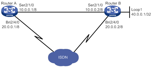
Configuration procedure
1. Configure Router A:
# Create dialer group 1 and configure a dial rule for it.
<RouterA> system-view
[RouterA] dialer-group 1 rule ip permit
# Configure an IP address for interface BRI 2/4/0.
[RouterA] interface bri 2/4/0
[RouterA-Bri2/4/0] ip address 20.0.0.1 8
# Enable traditional DDR on the interface.
[RouterA-Bri2/4/0] dialer circular enable
# Associate the interface with dialer group 1.
[RouterA-Bri2/4/0] dialer-group 1
# Configure the dial string for calling 40.0.0.1.
[RouterA-Bri2/4/0] dialer route ip 40.0.0.1 dial-number 8810052
[RouterA-Bri2/4/0] quit
# Configure an IP address for Serial 2/1/0.
[RouterA] interface serial 2/1/0
[RouterA-Serial2/1/0] ip address 10.0.0.1 8
# Enable PPP encapsulation on the interface.
[RouterA-Serial2/1/0] link-protocol ppp
[RouterA-Serial2/1/0] quit
# Configure OSPF.
[RouterA] ospf
[RouterA-ospf-1] area 0
[RouterA-ospf-1-area-0.0.0.0] network 10.0.0.0 0.255.255.255
[RouterA-ospf-1-area-0.0.0.0] network 20.0.0.0 0.255.255.255
[RouterA-ospf-1-area-0.0.0.0] quit
[RouterB-ospf-1] import-route direct
[RouterA-ospf-1] quit
# Create a dynamic route backup group.
[RouterA] standby routing-group 1 rule ip 30.0.0.1 32
# Configure the routes used by the serial interface to adopt higher priorities over those used by the dialup interface.
[RouterA] interface bri 2/4/0
[RouterA-Bri2/4/0] ospf cost 2000
[RouterA-Bri2/4/0] ospf network-type broadcast
# Enable dynamic route backup on BRI 2/4/0.
[RouterA-Bri2/4/0] standby routing-group 1
2. Configure Router B:
# Create dialer group 1 and configure a dial rule for it.
<RouterB> system-view
[RouterB] dialer-group 1 rule ip permit
# Configure an IP address for interface BRI 2/4/0.
[RouterB] interface bri 2/4/0
[RouterB-Bri2/4/0] ip address 20.0.0.2 8
# Enable traditional DDR on the interface.
[RouterB-Bri2/4/0] dialer circular enable
# Associate the interface with dialer group 1.
[RouterB-Bri2/4/0] dialer-group 1
[RouterB-Bri2/4/0] quit
# Configure an IP address for Serial 2/1/0.
[RouterB] interface serial 2/1/0
[RouterB-Serial2/1/0] ip address 10.0.0.2 8
# Enable PPP encapsulation on the interface.
[RouterB-Serial2/1/0] link-protocol ppp
[RouterB-Serial2/1/0] quit
# Configure an IP address for interface Loopback 1.
[RouterB] interface loopback 1
[RouterB-Loopback1] ip address 40.0.0.1 32
[RouterB-Loopback1] quit
# Configure OSPF.
[RouterB] ospf
[RouterB-ospf-1] area 0
[RouterB-ospf-1-area-0.0.0.0] network 10.0.0.0 0.255.255.255
[RouterB-ospf-1-area-0.0.0.0] network 20.0.0.0 0.255.255.255
[RouterB-ospf-1-area-0.0.0.0] network 40.0.0.0 0.0.0.0
[RouterB-ospf-1-area-0.0.0.0] quit
[RouterB-ospf-1] import-route direct
Dynamic route backup for bundle DDR configuration example
Network requirements
As shown in Figure 67, Router A and Router B are directly connected through their serial interfaces. They are also connected to the ISDN through their ISDN BRI interfaces. The telephone number of Router B is 8810010. The telephone number of Router B is 8810052.
Enable dynamic route backup on Router A to monitor network segment 30.0.0.0/8 connected to Router B.
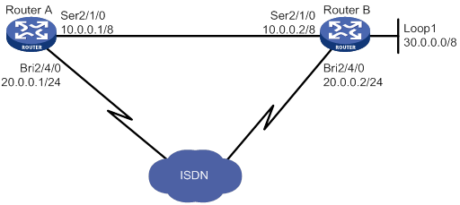
Configuration procedure
1. Configure Router A:
# Create dialer group 1 and configure a dial rule for it.
<RouterA> system-view
[RouterA] dialer-group 1 rule ip permit
Create a local user userb for Router B, and configure the service type as PPP.
[RouterA] local-user userb class network
[RouterA-luser-network-userb] password simple userb
[RouterA-luser-network-userb] service-type ppp
[RouterA-luser-network-userb] quit
# Create a dynamic route backup group on Dialer 0.
[RouterA] interface dialer 0
[RouterA] standby routing-group 1 rule ip 30.0.0.1 32
# Configure an IP address for the interface.
[RouterA-Dialer0] ip address 20.0.0.1 24
# Enable PPP encapsulation on the interface.
[RouterA-Dialer0] link-protocol ppp
# Configure CHAP authentication on the interface.
[RouterA-Dialer0] ppp authentication-mode pap
[RouterA-Dialer0] ppp pap local-user usera password simple usera
# Enable dynamic route backup on the interface.
[RouterA-Dialer0] standby routing-group 1
# Enable bundle DDR on the interface.
[RouterA-Dialer0] dialer bundle enable
# Specify the host name of the remote router allowed to call in.
[RouterA-Dialer0] dialer peer-name userb
# Associate the interface with dialer group 1.
[RouterA-Dialer0] dialer-group 1
# Configure the dial string for calling Router B.
[RouterA-Dialer0] dialer number 8810052
[RouterA-Dialer0] quit
# Assign interface BRI 2/4/0 to Dialer 0.
[RouterA] interface bri 2/4/0
[RouterA-Bri2/4/0] dialer bundle-member 0
# Configure PAP authentication on BRI 2/4/0.
[RouterA-Bri2/4/0] ppp authentication-mode pap
[RouterA-Bri2/4/0] ppp pap local-user usera password simple usera
[RouterA-Bri2/4/0] quit
# Configure an IP address for Serial 2/1/0.
[RouterA] interface serial 2/1/0
[RouterA-Serial2/1/0] ip address 10.0.0.1 8
# Enable PPP encapsulation on the interface.
[RouterA-Serial2/1/0] link-protocol ppp
[RouterA-Serial2/1/0] quit
# Configure RIP.
[RouterA] rip
[RouterA-rip-1] network 10.0.0.0
[RouterA-rip-1] network 20.0.0.0
[RouterA-rip-1] import-route direct
[RouterA-rip-1] quit
# Configure the routes used by the serial interface to adopt higher priorities than those used by the dialup interface.
[RouterA] interface bri 2/4/0
[RouterA-Bri2/4/0] rip metricin 2
2. Configure Router B:
# Create dialer group 1 and configure a dial rule for it.
<RouterB> system-view
[RouterB] dialer-group 1 rule ip permit
# Create a local user usera for Router A, and configure the service type as PPP.
[RouterB] local-user usera class network
[RouterB-luser-network-usera] password simple usera
[RouterB-luser-network-usera] service-type ppp
[RouterB-luser-network-usera] quit
# Configure an IP address for Dialer 0.
[RouterB] interface dialer 0
[RouterB-Dialer0] ip address 20.0.0.2 24
# Enable PPP encapsulation on the interface.
[RouterB-Dialer0] link-protocol ppp
# Configure PAP authentication on the interface.
[RouterB-Dialer0] ppp authentication-mode pap
[RouterB-Dialer0] ppp pap local-user userb password simple userb
# Enable bundle DDR on the interface.
[RouterB-Dialer0] dialer bundle enable
# Specify the host name of the remote router allowed to call in.
[RouterB-Dialer0] dialer peer-name usera
# Associate the interface with dialer group 1.
[RouterB-Dialer0] dialer-group 1
# Configure the dial string for calling Router A.
[RouterB-Dialer0] dialer number 8810010
[RouterB-Dialer0] quit
# Assign interface BRI 2/4/0 to Dialer 0.
[RouterB] interface bri 2/4/0
[RouterB-Bri2/4/0] dialer bundle-member 0
# Configure PAP authentication on the interface.
[RouterB-Bri2/4/0] ppp authentication-mode pap
[RouterB-Bri2/4/0] ppp pap local-user userb password simple userb
[RouterB-Bri2/4/0] quit
# Configure an IP address for Serial 2/1/0.
[RouterB] interface serial 2/1/0
[RouterB-Serial2/1/0] ip address 10.0.0.2 8
# Enable PPP encapsulation on the interface.
[RouterB-Serial2/1/0] link-protocol ppp
[RouterB-Serial2/1/0] quit
# Configure an IP address for interface Loopback 1.
[RouterB] interface loopback 1
[RouterB-Loopback1] ip address 30.0.0.1 32
[RouterB-Loopback1] quit
# Configure RIP.
[RouterB] rip
[RouterB-rip-1] network 10.0.0.0
[RouterB-rip-1] network 20.0.0.0
[RouterB-rip-1] network 30.0.0.0
[RouterB-rip-1] import-route direct
Configuration example for dynamic route backup for multiple networks
Network requirements
As shown in Figure 68, Router A and Router B are directly connected through serial interfaces running PPP. They are also connected through an ISDN switched network, enabling them to call each other by using traditional DDR. The telephone number of Router A is 660330, and that of Router B is 660220.
Configure dynamic route backup on Router A to monitor the networks 10.0.0.1/8, 11.0.0.1/8, and 12.0.0.1/8, which are all connected to Router B.
The PPP link acts as the primary link between Router A and Router B. When the routes to all the three networks become invalid, Router A automatically initiates a secondary link through ISDN to Router B.
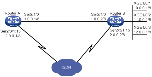
This network diagram only illustrates a simple application where a dynamic route backup group is used to monitor multiple subnets. In actual use, the monitored networks can be connected to multiple devices.
Configuration procedure
1. Configure Router A:
# Create dialer group 1 and configure a dial rule for it.
<RouterA> system-view
[RouterA] dialer-group 1 rule ip permit
# Create a dynamic route backup group to monitor three networks.
[RouterA] standby routing-group 1 rule ip 10.0.0.0 255.0.0.0
[RouterA] standby routing-group 1 rule 11.0.0.0 255.0.0.0
[RouterA] standby routing-group 1 rule ip 12.0.0.0 255.0.0.0
# Bundle timeslots on the CE1 interface into a PRI group.
[RouterA] controller e1 2/3/1
[RouterA-E1 2/3/1] pri-set
[RouterA-E1 2/3/1] quit
# Configure an IP address for Serial 2/1/0.
[RouterA] interface serial 2/1/0
[RouterA-Serial2/1/0] ip address 1.0.0.1 255.0.0.0
# Enable PPP encapsulation on the interface.
[RouterA-Serial2/1/0] link-protocol ppp
[RouterA-Serial2/1/0] quit
# Configure an IP address for Serial 2/3/1:15.
[RouterA] interface serial 2/3/1:15
[RouterA-Serial2/3/1:15] ip address 2.0.0.1 255.0.0.0
# Enable traditional DDR on the interface.
[RouterA-Serial2/3/1:15] dialer circular enable
# Associate the interface with dialer group 1.
[RouterA-Serial2/3/1:15] dialer-group 1
# Configure the dial string for calling the network 10.0.0.1/8.
[RouterA-Serial2/3/1:15] dialer route ip 10.0.0.0 mask 8 dial-number 660220
# Enable dynamic route backup on the interface.
[RouterA-Serial2/3/1:15] standby routing-group 1
[RouterA-Serial2/3/1:15] quit
# Configure RIP.
[RouterA] rip
[RouterA-rip-1] network 1.0.0.0
[RouterA-rip-1] network 2.0.0.0
[RouterA-rip-1] import-route direct
# Configure the routes used by the serial interface to adopt higher priorities than those used by the dialup interface.
[RouterA] interface serial 2/3/1:15
[RouterA-Serial2/3/1:15] rip metricin 2
2. Configure Router B:
# Create dialer group 1 and configure a dial rule for it.
[RouterB] system
[RouterB] dialer-group 1 rule ip permit
# Bundle timeslots on the CE1 interface into a PRI group.
[RouterB] controller e1 2/3/1
[RouterB-E1 2/3/1] pri-set
[RouterB-E1 2/3/1] quit
# Configure an IP address for Serial 2/1/0.
[RouterB] interface serial 2/1/0
[RouterB-Serial2/1/0] ip address 1.0.0.2 255.0.0.0
# Enable PPP encapsulation on the interface.
[RouterB-Serial2/1/0] link-protocol ppp
[RouterB-Serial2/1/0] quit
# Configure an IP address for Serial 2/3/1:15.
[RouterB] interface serial 2/3/1:15
[RouterB-Serial2/3/1:15] ip address 2.0.0.2 255.0.0.0
# Enable traditional DDR on the interface.
[RouterB-Serial2/3/1:15] dialer circular enable
# Associate the interface with dialer group 1.
[RouterB-Serial2/3/1:15] dialer-group 1
# Configure the dial string for calling Serial 2/3/1:15 on Router A.
[RouterB-Serial2/3/1:15] dialer route ip 2.0.0.1 mask 8 dial-number 660330
[RouterB-Serial2/3/1:15] quit
# Configure the Ethernet interfaces connecting to the networks.
[RouterB] interface gigabitethernet 1/0/1
[RouterB-GigabitEthernet1/0/1] ip address 10.0.0.1 255.0.0.0
[RouterB-GigabitEthernet1/0/1] quit
[RouterB] interface gigabitethernet 1/0/2
[RouterB-GigabitEthernet1/0/2] ip address 11.0.0.1 255.0.0.0
[RouterB-GigabitEthernet1/0/2] quit
[RouterB] interface ethernet 1/0/3
[RouterB-GigabitEthernet1/0/3] ip address 12.0.0.1 255.0.0.0
[RouterB-GigabitEthernet1/0/3] quit
# Configure RIP.
[RouterB] rip
[RouterB-rip-1] network 1.0.0.0
[RouterB-rip-1] network 2.0.0.0
[RouterB-rip-1] network 10.0.0.0
[RouterB-rip-1] network 11.0.0.0
[RouterB-rip-1] network 12.0.0.0
[RouterB-rip-1] import-route direct
Troubleshooting
Failure to establish a dialup connection
Symptom
DDR dialup connection cannot be established because the modem does not dial when the router forwards data.
Solution
To resolve the problem:
1. Verify that the modem and phone cable connections are correct, and that the modem initialization process is correct.
2. Verify that the dialup interface, if it is synchronous/asynchronous, is configured as an asynchronous interface in protocol mode.
3. Verify that DDR is enabled on the dialup interface.
4. Verify that a dialer route or dialer number command is available for the packets.
Ping failure
Symptom
The remote end cannot be pinged after the modem is connected.
Solution
To resolve the problem:
1. Use the debugging ppp all command to verify that the two ends use the same link layer encapsulation and have correct PPP parameters configured for authentication.
2. Verify that a correct IP address is assigned to the dialup interface.
3. Verify that DDR is enabled on the dialup interface.
4. Verify that the correct dialer-group and dialer-group rule commands are configured and associated to ensure that the packets can pass.
5. Use the debugging dialer event and debugging dialer packet commands to locate the problem.
Configuring Frame Relay
Overview
Frame Relay uses statistical multiplexing technology and can establish multiple virtual circuits over a single physical cable to fully utilize network bandwidth. Frame Relay uses data link connection identifiers (DLCIs) to identify virtual circuits. Frame Relay uses the Local Management Interface (LMI) protocol to maintain the status of each virtual circuit.
The following interfaces support Frame Relay:
· Synchronous serial interfaces, including synchronous serial interfaces derived from other interfaces.
· POS interfaces.
Frame Relay interface types
As shown in Figure 69:
· A Frame Relay network provides data communications between user devices such as routers and hosts. The user devices are also called data terminal equipment (DTE).
· The devices that provide access to the Frame Relay network for DTEs are called data circuit-terminating equipment (DCE).
Frame Relay interfaces can only be user-to-network interfaces (UNIs). A DCE is connected to a DTE through UNI interfaces. UNI interfaces include the following types:
· DTE interface—The UNI interface on the DTE side.
· DCE interface—The UNI interface on the DCE side.
A DTE interface can connect only to a DCE interface. On a Frame Relay switch, the Frame Relay interface type must be DCE.
As shown in Figure 69:
· Router B and Router C form a simple Frame Relay network.
· DTE devices Router A and Router D are attached to the network.
The interface type DTE or DCE is identified only for the UNI interfaces. A virtual circuit between two DTE devices can be assigned different DLCIs on different segments.
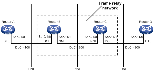
Virtual circuit
Virtual circuits are logical connections established between two devices. Depending on how they are established, virtual circuits include the following types:
· Permanent virtual circuit (PVC)—A PVC is manually configured or dynamically learned through the LMI negotiation. The availability of a PVC must be detected before the PVC can be used.
· Switched virtual circuit (SVC)—An SVC is dynamically established between two devices through calls. The network provides data transmission services on established SVCs. The terminal users can terminate an SVC through clearing the call.
Unlike SVCs, PVCs rarely break or disconnect. PVCs are used more than SVCs.
On a DTE device, the state of a PVC is determined by the DCE device. On a DCE device, the state of a PVC depends on the way that the DCE device is connected to the DTE device.
· When the DCE device is directly connected to the DTE device, they use LMI to negotiate the state of a PVC.
· When the DCE device is connected to the DTE device through a Frame Relay network, the state of a PVC is determined by the LMI negotiation result and the virtual circuit state in the Frame Relay network.
DLCI
A DLCI uniquely identifies a virtual circuit on a physical link and has local significance only for that link. A DLCI can be used on different physical ports to address different virtual circuits. A virtual circuit between two DTE devices can be addressed with different DLCIs at the two ends, as shown in Figure 69.
Because the virtual circuits in a Frame Relay network are connection oriented, each DLCI on a physical port is destined for a different peer device. DLCIs are the Frame Relay addresses of peer devices.
The maximum number of PVCs that can be created on a Frame Relay interface is 1024. The user configurable DLCIs for the PVCs are in the range 16 to 1007. Other DLCIs are reserved. For example, DLCI 0 and DLCI 1023 are reserved for the LMI protocol to transfer control messages.
Frame Relay address mapping
Frame Relay address mapping associates the protocol address of a peer device with a Frame Relay address (local DLCI). Then, the upper-layer protocol, for example, IP, can locate the peer device.
For example, an IPv4 or IPv6 packet is transmitted across a Frame Relay network as follows:
1. When a DTE device receives an IPv4 or IPv6 packet, the DTE device looks up the IP routing table for the outgoing interface and next-hop address.
2. When the outgoing interface is enabled with Frame Relay encapsulation, the device looks up the next-hop address in the address-to-DLCI mappings for the DLCI.
3. The packet is transmitted over the virtual circuit identified by the DLCI.
The address-to-DLCI mappings include the following types:
· Static—Manually created.
· Dynamic—Created through InARP or Inverse Neighbor Discovery (IND).
Frame Relay uses InARP to create an address-to-DLCI mapping through the following process:
4. InARP sends an InARP request to the peer end through a virtual circuit at the InARP request interval during an InARP learning process when the following conditions exist:
? A new virtual circuit is established.
? The local interface is configured with an IPv4 address.
The InARP request carries the local IPv4 address. By default, the InARP request interval during an InARP learning process (the detection timer) is 60 seconds.
5. When the peer device receives the InARP request, the peer device obtains the local IPv4 address and creates an address-to-DLCI mapping. At the same time, the peer device responds with an InARP reply carrying its IPv4 address.
6. When the local device receives the InARP reply, it creates an address-to-DLCI mapping.
7. After the local device creates the address-to-DLCI mapping, the local device modifies the InARP request interval to 12 minutes (the aging timer).
The aging timer is fixed. When the aging timer expires, the local device continues to send InARP requests.
8. The local device sets the aging timer value to the detection interval when the following conditions exist:
? The aging timer expires.
? The local device has not received any InARP replies.
9. When the local device has not received any InARP replies within three detection intervals, the learned dynamic address-to-DLCI mapping is deleted.
When the local device has not received InARP replies within a detection interval, the local device continues to send InARP requests. The local device stops sending InARP packets until the local interface is not configured with an IPv4 address or the local PVC is inactive.
IND creates IPv6 address-to-DLCI mappings in a way similar to InARP.
LMI protocol
Frame Relay uses the LMI protocol to manage PVCs, including the following operations:
· Notify the addition of a PVC.
· Detect the deletion of a PVC.
· Monitor PVC status changes.
· Verify link integrity.
The system supports the following LMI standards:
· ITU-T Q.933 Annex A.
· ANSI T1.617 Annex D.
· Nonstandard LMI (compatible with other vendors).
To communicate properly, the DTE and the DCE must use the same type of LMI.
LMI messages
LMI messages include the following types:
· Status enquiry message—A DTE sends status enquiry messages regularly to a DCE to request the status of individual PVCs or verify the link integrity.
· Status message—When a DCE receiving a status enquiry message, the DCE responds with a status message. The status message is used to transmit the PVC status or verify the link integrity.
Status enquiry messages and status messages include the following types:
· Full status—Verifies the link integrity and transmits the PVC status.
· Link integrity verification (LIV)—Verifies the link integrity.
LMI negotiation parameters
Table 7 lists the parameters ITU-T Q.933 Annex A uses for message exchange. You can configure these parameters to optimize device performance.
Table 7 LMI negotiation parameters
|
Device role |
Timer/counter |
Value range |
Default value |
Description |
|
DTE |
Full status polling counter (N391) |
1 to 255 |
6 |
Sets the ratio of link integrity request messages sent to full status enquiry messages sent. The ratio is (N391-1):1. |
|
Error threshold counter (N392) |
1 to 10 |
3 |
Sets the number of errors required for LMI to declare a link dead, within the event count specified by N393. |
|
|
Monitored events counter (N393) |
1 to 10 |
4 |
Sets the monitored event count. If the number of errors within the N393 status enquiry messages reaches N392, a DTE considers that the error threshold is reached. |
|
|
Keepalive (link integrity verification polling) timer (T391) |
0 to 32767 0 means LMI disabled. |
10 |
Sets the interval (in seconds) at which a DTE sends a status enquiry message. An error is recorded if the DTE has not received any replies when the timer expires. |
|
|
DCE |
Error threshold counter (N392) |
1 to 10 |
3 |
Sets the number of errors required for LMI to declare a link dead, within the event count specified by N393. |
|
Monitored events count (N393) |
1 to 10 |
4 |
Sets the monitored event count. If the number of errors within the N393 status enquiry messages reaches N392, a DCE considers that the error threshold is reached. |
|
|
Keepalive (polling verification) timer (T392) |
5 to 30 |
15 |
Sets the interval (in seconds) for receiving a status enquiry message. If a DCE has not received any status enquiry messages when the timer expires, an error is recorded. |
How LMI works
LMI works in the following process:
? When V391<N391, the DTE sends a link integrity verification message and requests only the link integrity.
? When V391=N391, the following events occur:
- V391 is reset to 0.
- The DTE sends a full status enquiry message to request not only the link integrity but also the status of all PVCs.
3. When the DTE receives a reply, the DTE updates the link status and PVC status. If the DTE has not received status messages when the T391 timer expires, the DTE records the error and increases the error count by one. If the number of errors exceeds N392 among N393 events, the DTE considers that the physical link and all virtual circuits unavailable and will not use them to forward packets.
Application scenarios
With Frame Relay, you can construct a public or private network as shown in Figure 70 and construct direct connections between data devices as shown in Figure 71.
Figure 70 Interconnecting LANs through a Frame Relay network
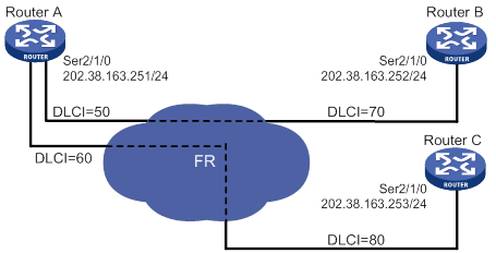
Figure 71 Interconnecting LANs through a dedicated line
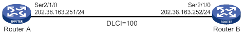
Feature and hardware compatibility
This feature is supported only on Layer 2 Ethernet ports on the following modules:
· CE3/CT3.
· E1/T1.
· E1-F/T1-F.
· POS/CPOS.
· SAE.
IPv6-related parameters are not supported on the following routers:
· MSR810/810-W/810-W-DB/810-LM/810-W-LM/810-10-PoE/810-LM-HK/810-W-LM-HK/810-LMS/810-LUS.
· MSR3600-28-SI/3600-51-SI.
· MSR810-LM-GL/810-W-LM-GL/830-6EI-GL/830-10EI-GL/830-6HI-GL/830-10HI-GL.
Frame Relay configuration task list
|
Configure DTE-side Frame Relay: · (Required.) Configuring basic DTE-side Frame Relay · (Required.) Configuring local Frame Relay virtual circuits · (Required.) Configuring Frame Relay address mappings · (Optional.) Configuring Frame Relay subinterfaces · (Optional.) Configuring Frame Relay IPHC · (Optional.) Configuring Frame Relay STAC compression · (Optional.) Configuring Frame Relay FRF.12 fragmentation · (Optional.) Enabling SNMP notifications for Frame Relay |
|
Configure DCE-side Frame Relay: · (Required.) Configuring basic DCE-side Frame Relay · (Required.) Configuring local Frame Relay virtual circuits · (Required.) Configuring Frame Relay address mappings · (Optional.) Configuring Frame Relay subinterfaces · (Optional.) Configuring Frame Relay IPHC · (Optional.) Configuring Frame Relay STAC compression · (Optional.) Configuring Frame Relay FRF.12 fragmentation · (Optional.) Enabling SNMP notifications for Frame Relay |
Configuring basic DTE-side Frame Relay
|
Step |
Command |
Remarks |
|
1. Enter system view. |
system-view |
N/A |
|
2. Enter the view of the interface connecting to the Frame Relay network. |
interface interface-type interface-number |
N/A |
|
3. Enable Frame Relay encapsulation on the interface. |
link-protocol fr |
By default, PPP encapsulation is enabled on interfaces except Ethernet interfaces and VLAN interfaces. |
|
4. (Optional.) Configure the encapsulation type for the Frame Relay interface. |
The default setting is IETF. |
|
|
5. (Optional.) Set the Frame Relay interface type to DTE. |
fr interface-type dte |
The default setting is DTE. |
|
6. (Optional.) Configure the Frame Relay LMI protocol type. |
fr lmi type { ansi | nonstandard | q933a } |
The default setting is q933a. |
|
7. (Optional.) Set the DTE-side N391 counter. |
fr lmi n391dte n391-value |
The default setting is 6. |
|
8. (Optional.) Set the DTE-side N392 counter. |
fr lmi n392dte n392-value |
The default setting is 3. |
|
9. (Optional.) Set the DTE-side N393 counter. |
fr lmi n393dte n393-value |
The default setting is 4. |
|
10. (Optional.) Set the DTE-side T391 timer. |
timer-hold seconds |
The default setting is 10 seconds. |
Configuring basic DCE-side Frame Relay
|
Step |
Command |
Remarks |
|
1. Enter system view. |
system-view |
N/A |
|
2. Enter the view of the interface connecting to the Frame Relay network. |
interface interface-type interface-number |
N/A |
|
3. Enable Frame Relay encapsulation on the interface. |
link-protocol fr |
By default, PPP encapsulation is enabled on interfaces except Ethernet interfaces, VLAN interfaces, and ATM interfaces. |
|
4. (Optional.) Configure the encapsulation type for the Frame Relay interface. |
fr encapsulation { ietf | nonstandard } |
The default setting is IETF. |
|
5. (Optional.) Set the Frame Relay interface type to DCE. |
fr interface-type dce |
The default setting is DTE. |
|
6. (Optional.) Configure the Frame Relay LMI protocol type. |
fr lmi type { ansi | nonstandard | q933a } |
The default setting is q933a. |
|
7. (Optional.) Set the DCE-side N392 counter. |
The default setting is 3. |
|
|
8. (Optional.) Set the DCE-side N393 counter. |
The default setting is 4. |
|
|
9. (Optional.) Set the DCE-side T392 timer. |
The default setting is 15 seconds. |
Configuring local Frame Relay virtual circuits
The available methods of creating virtual circuits vary by interface type.
· On a DCE main interface or subinterface, the virtual circuit must be manually created.
· On a DTE main interface, virtual circuits can be automatically created through negotiation with the peer interface or manually created.
· On a DTE subinterface, the virtual circuit must be manually created.
This section describes how to manually create virtual circuits.
Configuration restrictions and guidelines
When you configure local Frame Relay virtual circuits, follow these restrictions and guidelines:
· When manually creating virtual circuits on a DTE interface, make sure their DLCIs are the same as those used on the DCE.
· If the DLCI of a virtual circuit changes on a DCE interface, perform one of the following tasks for the DTE to quickly relearn the correct address-to-DLCI mappings. Before performing either of the following tasks, make sure no services will be interrupted.
? Reset both the DCE and DTE interfaces.
? Execute the reset inarp command on both ends.
· The DLCI of a virtual circuit must be unique on a main interface and all its subinterfaces.
Configuration procedure
To configure a local Frame Relay virtual circuit:
|
Step |
Command |
Remarks |
|
1. Enter system view. |
system-view |
N/A |
|
2. Enter interface view. |
interface interface-type interface-number |
The interface can be a main interface or subinterface. |
|
3. Create a virtual circuit on the interface. |
fr dlci dlci-number |
By default, no virtual circuits exist. |
|
4. (Optional.) Configure the encapsulation type for the virtual circuit. |
By default, a virtual circuit uses the encapsulation type configured on its interface. |
|
|
5. (Optional.) Allow broadcast packets on the virtual circuit. |
By default, broadcast packets are forbidden on static virtual circuits and allowed on dynamic virtual circuits. When a virtual circuit allows broadcast packets, the broadcast or multicast packets on the Frame Relay interface of the virtual circuit are also transmitted on the virtual circuit. |
Configuring Frame Relay address mappings
Use either of the following methods to configure Frame Relay address mappings:
· Static—Manually create static address-to-DLCI mappings between peer IPv4 or IPv6 addresses and local DLCIs. Use this method when the network topology is stable and no new users are expected for a specific period of time. Because static address-to-DLCI mappings do not change, the network connections are stable, and attacks from unknown users are avoided.
· Dynamic—Use InARP or IND to dynamically create IPv4 or IPv6 address-to-DLCI mappings. Use this method in complex networks. Make sure the peer devices also support InARP or IND.
Configuring a static address-to-DLCI mapping
|
Step |
Command |
Remarks |
|
1. Enter system view. |
system-view |
N/A |
|
2. Enter interface view. |
interface interface-type interface-number |
The interface can be a main interface or P2MP subinterface. |
|
3. Create a static Frame Relay address-to-DLCI mapping. |
·
Create an IPv4 address-to-DLCI mapping: ·
Create an IPv6 address-to-DLCI mapping: |
By default, no static Frame Relay address-to-DLCI mappings exist. When the DLCI specified in this command does not exist, the DLCI is automatically created. As a best practice, if you configure an IPv6 address-to-DLCI mapping, also configure an address-to-DLCI mapping for the link-local address of the peer. This ensures that packets with the link-local address as the destination address can be forwarded. |
Configuring dynamic IPv4 address mapping
|
Step |
Command |
Remarks |
|
1. Enter system view. |
system-view |
N/A |
|
2. Enter interface view. |
interface interface-type interface-number |
N/A |
|
3. Enable Frame Relay InARP for dynamic address mapping. |
fr inarp ip [ dlci-number ] |
By default, Frame Relay InARP is enabled for dynamic address mapping. |
|
4. Set the InARP request interval during the InARP learning process. |
The default setting is 60 seconds. |
Configuring dynamic IPv6 address mapping
|
Step |
Command |
Remarks |
|
1. Enter system view. |
system-view |
N/A |
|
2. Enter interface view. |
interface interface-type interface-number |
N/A |
|
3. Enable Frame Relay IND for dynamic address mapping. |
fr ipv6 ind [ dlci-number ] |
By default, Frame Relay IND is disabled for dynamic address mapping. |
|
4. Set the IND request interval during the IND learning process. |
ipv6 ind holdtime seconds |
The default setting is 30 seconds. |
|
5. Set the interval between continuous IND requests. |
ipv6 ind solicitation retrans-timer seconds |
The default setting is 1 second. |
Configuring Frame Relay subinterfaces
Frame Relay provides main interfaces and subinterfaces. A subinterface is a logical interface. It can be configured with protocol addresses and virtual circuits. One physical interface can include multiple subinterfaces. The subinterfaces and main interfaces can all be configured with virtual circuits to connect to peer devices.
Frame Relay subinterfaces include the following types:
· Point-to-point (P2P) subinterface—A P2P subinterface connects to a single peer device.
· Point-to-multipoint (P2MP) subinterface—A P2MP subinterface connects to multiple peer devices. A P2MP subinterface can be configured with multiple virtual circuits. An address-to-DLCI mapping can be configured for each virtual circuit and its connected peer network address. Address-to-DLCI mappings can be dynamically configured through InARP or manually configured.
The methods of configuring a virtual circuit and address-to-DLCI mapping for P2P subinterfaces and P2MP subinterfaces have the following differences:
· P2P subinterface—Because a P2P subinterface has only one peer address, the peer address is determined when a virtual circuit is configured for the subinterface. You cannot configure static address-to-DLCI mappings or enable InARP for a P2P subinterface.
· P2MP subinterface—For a P2MP subinterface, a peer address can be mapped to the local DLCI through static address-to-DLCI mappings or InARP. To enable InARP for dynamic address mapping on a P2MP subinterface, you only need to enable InARP on the main interface. If static address-to-DLCI mappings are needed, you must configure a static address-to-DLCI mapping for each virtual circuit.
To configure a Frame Relay subinterface:
|
Step |
Command |
Remarks |
|
1. Enter system view. |
system-view |
N/A |
|
2. Create a subinterface and enter subinterface view. |
interface interface-type interface-number.subnumber [ p2mp | p2p ] |
By default, no Frame Relay subinterfaces exist. If you do not specify a subinterface type when you create a Frame Relay interface, a P2MP subinterface is created. |
|
3. Configure a virtual circuit on the Frame Relay subinterface. |
On a Frame Relay subinterface, virtual circuits must be created manually. |
|
|
4. Configure address mapping. |
Available on P2MP subinterfaces. |
Configuring Frame Relay IPHC
IP header compression (IPHC) reduces the amount of bandwidth consumed by packet headers. It is typically used for voice communication on low-speed links.
IPHC includes the following types:
· RTP header compression—Compresses the IP/UDP/RTP header (40 bytes in total) in packets.
· TCP header compression—Compresses the TCP/IP header (40 bytes in total) in packets.
For the duration of a connection, some fields in the RTP/UDP/IP or TCP/IP header do not change, and other fields change in a predictable way. The IPHC compressor and decompressor maintain the fields that do not change and the fields that change in a predictable way. The compressor only needs to transmit the fields of a header that change.
Configuration restrictions and guidelines
When you configure Frame Relay IPHC, follow these restrictions and guidelines:
· To make IPHC take effect on a link, you must enable Frame Relay IPHC on both ends of the link.
· You can configure Frame Relay IPHC on either an interface or a virtual circuit. The settings on an interface take effect on all virtual circuits of the interface. The settings on a virtual circuit take effect only on the virtual circuit. When the interface settings are different from the virtual circuit settings, the virtual circuit settings take effect.
· When the encapsulation type is IETF, IPHC negotiation is triggered after you enable IPHC. IPHC takes effect only when IPHC negotiation succeeds. When the encapsulation type is nonstandard, IPHC takes effect without negotiation. In this case, the encapsulation type must be nonstandard on both ends of the link.
· Compression does not stop after you disable IPHC on an interface or virtual circuit. To stop compression, you must also execute the shutdown/undo shutdown command sequence on the interface or virtual circuit.
· You can set the maximum number of RTP/TCP header-compression connections only after you enable IPHC on an interface or virtual circuit. The configuration takes effect after you execute the shutdown/undo shutdown command sequence on the interface or virtual circuit. After you disable IPHC, the configuration is deleted.
· The maximum number of RTP/TCP header-compression connections configured on an interface is inherited by all virtual circuits of the interface. If you set a different maximum number on a virtual circuit of the interface, the configuration on the virtual circuit takes effect.
· Frame Relay IPHC and STAC compression are mutually exclusive.
Configuring Frame Relay IPHC on an interface
|
Step |
Command |
Remarks |
|
1. Enter system view. |
system-view |
N/A |
|
2. Enter interface view. |
interface interface-type interface-number |
N/A |
|
3. Enable Frame Relay IPHC. |
fr compression iphc enable [ nonstandard ] |
By default, Frame Relay IPHC is disabled. If you specify the nonstandard keyword, only RTP header compression is supported, and TCP header compression is not supported. |
|
4. Set the maximum number of RTP header-compression connections allowed. |
fr compression iphc rtp-connections |
The default setting is 16. |
|
5. Set the maximum number of TCP header-compression connections allowed. |
fr compression iphc tcp-connections |
The default setting is 16. |
Configuring Frame Relay IPHC on a virtual circuit
|
Step |
Command |
Remarks |
|
1. Enter system view. |
system-view |
N/A |
|
2. Enter interface view. |
interface interface-type interface-number |
The interface can be a main interface or a subinterface. |
|
3. Create a virtual circuit on the interface. |
fr dlci dlci-number |
By default, no virtual circuits exist on an interface. |
|
4. Enable Frame Relay IPHC. |
fr compression iphc enable [ nonstandard ] |
By default, Frame Relay IPHC is disabled. If you specify the nonstandard keyword, only RTP header compression is supported, and TCP header compression is not supported. |
|
5. Set the maximum number of RTP header-compression connections allowed. |
fr compression iphc rtp-connections |
The default setting is 16. |
|
6. Set the maximum number of TCP header-compression connections allowed. |
fr compression iphc tcp-connections |
The default setting is 16. |
Configuring Frame Relay STAC compression
STAC compression is a payload compression method that applies to Frame Relay packets, InARP packets, and IND packets. STAC compression cannot compress LMI messages.
The two ends of a PVC negotiate the PVC state by using STAC control messages after STAC compression is enabled. The PVC state negotiation succeeds only when STAC compression is enabled on both ends of the PVC. After PVC state negotiation succeeds, both ends can transmit compressed packets on the PVC. If one end does not receive response messages from the peer after sending 10 control messages, it stops sending control messages. The PVC state negotiation fails.
Configuration restrictions and guidelines
When you configure Frame Relay STAC compression, follow these restrictions and guidelines:
· To make STAC compression take effect on a PVC, you must enable Frame Relay STAC compression on both ends of the PVC.
· STAC compression works only when the encapsulation type is IETF on both ends of a PVC. If the encapsulation type is not IETF when you enable STAC compression, the system automatically changes the encapsulation type to IETF.
· Frame Relay IPHC and STAC compression are mutually exclusive.
Configuring Frame Relay STAC compression on a virtual circuit
|
Step |
Command |
Remarks |
|
1. Enter system view. |
system-view |
N/A |
|
2. Enter interface view. |
interface interface-type interface-number |
The interface can be a main interface or a subinterface. |
|
3. Create a virtual circuit on the interface. |
fr dlci dlci-number |
By default, no virtual circuits exist on an interface. |
|
4. Enable STAC compression on the virtual circuit. |
fr compression stac enable |
By default, STAC compression is disabled on a virtual circuit. |
Configuring Frame Relay FRF.12 fragmentation
FRF.12 fragmentation divides large packets into smaller fragments at the sending end and reassembles the fragments at the receiving end. This process helps reduce the transmission delay for voice traffic when data traffic and voice traffic are transmitted together on low-speed links. FRF.12 fragmentation takes effect only on outgoing packets.
FRF.12 fragmentation includes the following types:
· NNI&UNI.
· End-to-end.
Only end-to-end FRF.12 fragmentation is supported in the current software version.
Configuration restrictions and guidelines
When you configure Frame Relay FRF.12 fragmentation, follow these restrictions and guidelines:
· FRF.12 fragmentation and Frame Relay traffic shaping are mutually exclusive on an interface. For more information about Frame Relay traffic shaping, see ACL and QoS Configuration Guide.
· An MFR interface does not support FRF.12 fragmentation.
? If both ends of a link are MFR interfaces, FRF.12 fragmentation does not take effect on either end.
? If one end of a link is a Frame Relay interface, FRF.12 fragmentation takes effect on the Frame Relay interface.
Configuring Frame Relay FRF.12 fragmentation on an interface
|
Step |
Command |
Remarks |
|
1. Enter system view. |
system-view |
N/A |
|
2. Enter interface view. |
interface interface-type interface-number |
N/A |
|
3. Enable FRF.12 fragmentation on the interface. |
fr fragment enable |
By default, FRF.12 fragmentation is disabled on an interface. |
|
4. (Optional.) Set the fragment size allowed on the interface. |
fr fragment size |
The default setting is 45 bytes. |
Enabling SNMP notifications for Frame Relay
After you enable SNMP notifications for Frame Relay, Frame Relay generates notifications for important events and sends the notifications to the SNMP module. For more information about SNMP notifications, see Network Management and Monitoring Configuration Guide.
To enable SNMP notifications for Frame Relay:
|
Step |
Command |
Remarks |
|
1. Enter system view. |
system-view |
N/A |
|
2. Enable SNMP notifications for Frame Relay. |
snmp-agent trap enable fr |
By default, SNMP notifications are disabled for Frame Relay. |
Displaying and maintaining Frame Relay
Execute the display commands in any view and the reset commands in user view.
|
Task |
Command |
|
Display Frame Relay IPv4 address mapping of interfaces. |
display fr map [ interface interface-type interface-number ] |
|
Display the LMI information of interfaces. |
display fr lmi [ interface interface-type interface-number ] |
|
Display information on Frame Relay PVCs and statistics about data sent and received on them. |
display fr pvc [ interface interface-type interface-number ] [ dlci dlci-number ] |
|
Display statistics for Frame Relay InARP packets. |
display fr inarp [ interface interface-type interface-number ] |
|
Display Frame Relay IPv6 address mapping of interfaces. |
display fr ipv6 map [ static | dynamic ] [ interface interface-type interface-number [ dlci dlci-number ] ] |
|
Display statistics for Frame Relay IPHC. |
|
|
Display statistics for Frame Relay STAC compression. |
display fr compression stac [ interface interface-type interface-number [ dlci dlci-number ] ] |
|
Display statistics for Frame Relay FRF.12 fragmentation. |
display fr fragment [ interface interface-type interface-number [ dlci dlci-number ] ] |
|
Clear the address-to-DLCI mappings established by InARP. |
reset fr inarp [ interface interface-type interface-number [ dlci dlci-number ] ] |
|
Clear the address-to-DLCI mappings established by IND. |
reset fr ipv6 ind [ interface interface-type interface-number [ dlci dlci-number ] ] |
|
Clear statistics of PVCs. |
reset fr pvc [ interface interface-type interface-number [ dlci dlci-number ] ] |
|
Clear statistics for Frame Relay IPHC. |
reset fr compression iphc { rtp | tcp } [ interface interface-type interface-number [ dlci dlci-number ] ] |
Frame Relay configuration example
Network requirements
As shown in Figure 72, configure Frame Relay so that Router A and Router B can communicate.
Configuration procedure
(Method 1) Using main interfaces
1. Configure Router A:
# Assign an IP address to interface Serial 2/1/0.
<RouterA> system-view
[RouterA] interface serial 2/1/0
[RouterA-Serial2/1/0] ip address 202.38.163.251 255.255.255.0
# Enable Frame Relay encapsulation on the interface.
[RouterA-Serial2/1/0] link-protocol fr
# Set the type of the interface to DCE.
[RouterA-Serial2/1/0] fr interface-type dce
# Configure a local virtual circuit.
[RouterA-Serial2/1/0] fr dlci 100
2. Configure Router B:
# Assign an IP address to interface Serial 2/1/0.
<RouterB> system-view
[RouterB] interface serial 2/1/0
[RouterB-Serial2/1/0] ip address 202.38.163.252 255.255.255.0
# Enable Frame Relay encapsulation on the interface.
[RouterB-Serial2/1/0] link-protocol fr
# Set the type of the interface to DTE.
[RouterB-Serial2/1/0] fr interface-type dte
[RouterB-Serial2/1/0] quit
(Method 2) Using subinterfaces
1. Configure Router A:
# Enable Frame Relay encapsulation on the interface Serial 2/1/0.
<RouterA> system-view
[RouterA] interface serial 2/1/0
[RouterA-Serial2/1/0] link-protocol fr
# Set the type of the interface Serial 2/1/0 to DCE.
[RouterA-Serial2/1/0] fr interface-type dce
[RouterA-Serial2/1/0] quit
# Create a subinterface Serial 2/1/0.1.
[RouterA] interface serial 2/1/0.1 p2p
# Configure the IP address and create a virtual circuit for the subinterface Serial 2/1/0.1.
[RouterA-Serial2/1/0.1] ip address 202.38.163.251 255.255.255.0
[RouterA-Serial2/1/0.1] fr dlci 100
2. Configure Router B:
# Enable Frame Relay encapsulation on interface Serial 2/1/0.
<RouterB> system-view
[RouterB] interface serial 2/1/0
[RouterB-Serial2/1/0] link-protocol fr
# Set the type of the interface Serial 2/1/0 to DTE.
[RouterB-Serial2/1/0] fr interface-type dte
[RouterB-Serial2/1/0] quit
# Create a subinterface Serial 2/1/0.1.
[RouterB] interface serial 2/1/0.1 p2p
# Configure the IP address and create a virtual circuit for the subinterface Serial 2/1/0.1.
[RouterB-Serial2/1/0.1] ip address 202.38.163.252 255.255.255.0
[RouterB-Serial2/1/0.1] fr dlci 100
[RouterB-Serial2/1/0.1] quit
Verifying the configuration
This section verifies the configuration used in method 1.
# On Router B, verify that the PVC is active.
PVC information for interface Serial2/1/0 (DTE, physically up)
DLCI: 100 Type: Dynamic Interface: Serial2/1/0
Encapsulation: IETF Broadcast
Creation time: 2014/02/19 01:38:00 Status: Active
Input: 2 packets, 60 bytes, 0 dropped
Output: 2 packets, 60 bytes, 0 dropped
# Verify that Router A and Router B can ping each other.
Ping 202.38.163.251 (202.38.163.251): 56 data bytes, press CTRL_C to break
56 bytes from 202.38.163.251: icmp_seq=0 ttl=255 time=76.007 ms
56 bytes from 202.38.163.251: icmp_seq=1 ttl=255 time=8.790 ms
56 bytes from 202.38.163.251: icmp_seq=2 ttl=255 time=1.630 ms
56 bytes from 202.38.163.251: icmp_seq=3 ttl=255 time=0.841 ms
56 bytes from 202.38.163.251: icmp_seq=4 ttl=255 time=1.012 ms
--- Ping statistics for 202.38.163.251 ---
5 packets transmitted, 5 packets received, 0.0% packet loss
round-trip min/avg/max/std-dev = 0.841/17.656/76.007/29.326 ms
Troubleshooting Frame Relay
The physical layer is down
Symptom
The physical layer is down.
Solution
To resolve this problem:
1. Verify that the physical line is working correctly.
2. Verify that the peer device is working correctly.
3. If the problem persists, contact H3C Support.
The physical layer is already up, but the link layer protocol is down
Symptom
The physical layer is already up, but the link layer protocol is down.
Solution
To resolve this problem:
1. Verify that Frame Relay is enabled on the peer devices.
2. Verify that one end is in DTE mode and the other end is in DCE mode if the two devices are directly connected.
3. Verify that both ends are using the same LMI protocol.
4. Execute the debugging lmi command to identify whether one status message is received for each status enquiry message. If not, examine the physical layer.
5. If the problem persists, contact H3C Support.
The link layer protocol is up, but the peer cannot be pinged
Symptom
The link layer protocol is up, but the peer cannot be pinged.
Solution
To resolve this problem:
1. Verify that the devices at both ends have configured correct address-to-DLCI mappings for the peer.
2. Verify that a route to the peer exists if the devices are not on the same subnet segment.
3. If the problem persists, contact H3C Support.
Configuring Multilink Frame Relay
Multilink Frame Relay (MFR) is a cost-effective bandwidth solution that is based on Frame Relay Forum Multilink Frame Relay UNI/NNI Implementation Agreement (FRF.16.1). This feature increases bandwidth by bundling multiple physical links into a logical link.
MFR uses the following concepts:
· Bundle—A virtual interface formed by combining multiple physical interfaces. A bundle corresponds to an MFR interface. A bundle is visible to the data link layer.
· Bundle link—Corresponds to a physical interface. A bundle contains and manages multiple bundle links, as shown in Figure 73. Bundle links are visible to the physical layer.
Figure 73 Bundle and bundle links
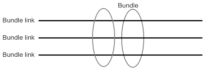
MFR interfaces support DTE and DCE interface types and QoS queuing mechanisms. Physical interfaces bundled into an MFR interface use the data link and network parameter settings of the MFR interface. Their original parameters settings do not work.
Feature and hardware compatibility
This feature is supported only on Layer 2 Ethernet ports on the following modules:
· CE3.
· CPOS.
· CT3.
· E1.
· E1-F.
· POS.
· SAE.
· T1.
· T1-F.
MFR configuration task list
|
Tasks at a glance |
|
(Required.) Configuring an MFR bundle |
|
(Required.) Configuring an MFR bundle link |
Configuring an MFR bundle
As a best practice to maximize bandwidth that can be used, bundle physical interfaces of the same speed in one bundle.
To configure an MFR bundle:
|
Step |
Command |
Remarks |
|
1. Enter system view. |
system-view |
N/A |
|
2. Create an MFR interface and enter MFR interface view. |
interface mfr { interface-number | interface-number.subnumber [ p2mp | p2p ] } |
By default, no MFR interfaces or subinterfaces exist. Before creating an MFR subinterface, make sure the main MFR interface already exists. |
|
3. (Optional.) Set a description for the MFR interface. |
description text |
By default, the description of an MFR interface is interface name Interface, for example, MFR0/0/2 Interface. |
|
4. (Optional.) Set the MFR bundle identifier. |
mfr bundle-name name |
The default bundle identifier is MFR + frame relay bundle number, for example, MFR0/0/2. You cannot set a bundle identifier in the MFR number format. |
|
5. (Optional.) Enable MFR fragmentation. |
mfr fragment enable |
By default, MFR fragmentation is disabled. |
|
6. (Optional.) Set the size of the MFR sliding window. |
mfr window-size number |
By default, the size of the MFR sliding window is the number of physical interfaces bundled by MFR. |
|
7. (Optional.) Set maximum fragment size allowed for bundle links. |
mfr fragment-size size |
The default setting is 300 bytes. |
|
8. (Optional.) Set the expected bandwidth for the MFR interface. |
bandwidth bandwidth-value |
By default, the expected bandwidth (in kbps) is the interface baud rate divided by 1000. |
|
9. (Optional.) Restore the default settings for the MFR interface |
default |
N/A |
|
10. Shut down and then bring up the MFR interface. |
a shutdown b undo shutdown |
By default, an MFR interface is up. |
|
11. (Optional.) Configure other parameters for the MFR interface. |
See "Configuring Frame Relay." |
The fr interface-type and fr inarp commands can be used only on main MFR interfaces. |
Configuring an MFR bundle link
|
Step |
Command |
Remarks |
|
1. Enter system view. |
system-view |
N/A |
|
2. Enter synchronous serial interface view or POS interface view. |
interface interface-type interface-number |
N/A |
|
3. Enable MFR encapsulation on the interface. |
link-protocol mfr |
By default, synchronous serial interfaces and POS interfaces use PPP encapsulation. |
|
4. Assign the interface to an MFR interface. |
fr mfr interface-number |
By default, an interface is not assigned to any MFR interfaces. |
|
5. (Optional.) Set the MFR bundle link identifier. |
mfr link-name name |
By default, the name of the current interface is used. |
|
6. (Optional.) Set the interval at which the MFR bundle link sends hello messages. |
mfr timer hello seconds |
The default setting is 10 seconds. Hello messages maintain link status. |
|
7. (Optional.) Set the time that the bundle link waits for a hello acknowledgment before resending the hello message. |
mfr timer ack seconds |
The default setting is 4 seconds. A hello acknowledgment notifies the peer that the local end received a hello message. |
|
8. (Optional.) Set the maximum number of times that the MFR bundle link can resend hello messages. |
mfr retry retries |
The default setting is 2. |
Displaying and maintaining MFR
Execute display commands in any view and reset commands in user view.
|
Task |
Command |
|
Display MFR interface information. |
display interface [ mfr [ interface-number ] ] [ brief [ description | down ] ] |
|
Display the configuration and statistics for MFR bundles and bundle links. |
display mfr [ interface interface-type interface-number | verbose ] |
|
Clear statistics for MFR interfaces. |
reset counters interface [ mfr [ interface-number | interface-number.subnumber ] ] |
MFR configuration example
Network requirements
As shown in Figure 74, use MFR to bind the physical links between Router A and Router B into a logical link with higher bandwidth than each physical link.
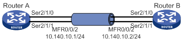
Configuration procedure
1. Configure Router A:
# Create interface MFR 0/0/2, and assign an IP address to the interface.
<RouterA> system-view
[RouterA] interface mfr0/0/2
[RouterA-MFR0/0/2] ip address 10.140.10.1 255.255.255.0
# Set the type of the interface to DTE.
[RouterA-MFR0/0/2] fr interface-type dte
# Configure a static Frame Relay address-to-DLCI mapping for the interface.
[RouterA-MFR0/0/2] fr map ip 10.140.10.2 100
[RouterA-MFR0/0/2] quit
# Bind Serial 2/1/0 and Serial 2/1/1 to MFR 0/0/2.
[RouterA] interface serial 2/1/0
[RouterA-Serial2/1/0] link-protocol mfr
[RouterA-Serial2/1/0] fr mfr mfr0/0/2
[RouterA-Serial2/1/0] quit
[RouterA] interface serial 2/1/1
[RouterA-Serial2/1/1] link-protocol mfr
[RouterA-Serial2/1/1] fr mfr mfr0/0/2
[RouterA-Serial2/1/1] quit
2. Configure Router B:
# Create interface MFR 0/0/2, and assign an IP address to the interface.
<RouterB> system-view
[RouterB] interface mfr0/0/2
[RouterB-MFR0/0/2] ip address 10.140.10.2 255.255.255.0
# Set the type of the interface to DCE.
[RouterB-MFR0/0/2] fr interface-type dce
# Create a virtual circuit for the interface.
[RouterB-MFR0/0/2] fr dlci 100
[RouterB-MFR0/0/2-fr-dlci-100] quit
# Configure a static Frame Relay address-to-DLCI mapping for the interface.
[RouterB-MFR0/0/2] fr map ip 10.140.10.1 100
[RouterB-MFR0/0/2] quit
# Bind Serial 2/1/0 and Serial 2/1/1 to MFR 0/0/2.
[RouterB] interface serial 2/1/0
[RouterB-Serial2/1/0] link-protocol mfr
[RouterB-Serial2/1/0] fr mfr mfr0/0/2
[RouterB-Serial2/1/0] quit
[RouterB] interface serial 2/1/1
[RouterB-Serial2/1/1] link-protocol mfr
[RouterB-Serial2/1/1] fr mfr mfr0/0/2
[RouterB-Serial2/1/1] quit
Verifying the configuration
# On Router A, verify that the PVC is active.
PVC information for interface MFR0/0/2 (DTE, physically up)
DLCI: 100 Type: Static Interface: MFR0/0/2
Encapsulation: IETF
Creation time: 2014/08/18 06:38:00 Status: Active
Input: 0 packets, 0 bytes, 0 dropped
Output: 0 packets, 0 bytes, 0 dropped
# Verify that Router A and Router B can ping each other.
Ping 10.140.10.2 (10.140.10.2): 56 data bytes, press CTRL_C to break
56 bytes from 10.140.10.2: icmp_seq=0 ttl=255 time=76.007 ms
56 bytes from 10.140.10.2: icmp_seq=1 ttl=255 time=8.790 ms
56 bytes from 10.140.10.2: icmp_seq=2 ttl=255 time=1.630 ms
56 bytes from 10.140.10.2: icmp_seq=3 ttl=255 time=0.841 ms
56 bytes from 10.140.10.2: icmp_seq=4 ttl=255 time=1.012 ms
--- Ping statistics for 10.140.10.2 ---
5 packets transmitted, 5 packets received, 0.0% packet loss
round-trip min/avg/max/std-dev = 0.841/17.656/76.007/29.326 ms
Assigning an interface to an HDLC link bundle,102
Associating 3G/4G link backup with a track entry,161
Associating a dial rule with a dialup interface,173
ATM configuration examples,139
ATM configuration task list,128
Binding the IMSI of the SIM card to an interface,164
Compatibility information,94
Compatibility information,44
Compatibility information,170
Compatibility information,4
Compatibility information,100
Configuration restrictions and guidelines,154
Configuring a 3G/4G network,158
Configuring a cellular interface for a 3G modem,156
Configuring a cellular interface for a 4G modem,156
Configuring a PPPoE client,50
Configuring a PVC,128
Configuring a PVC group,129
Configuring a trusted IMSI,162
Configuring an ATM interface,128
Configuring an Eth-channel interface for a 4G modem,156
Configuring an HDLC link bundle interface,101
Configuring an IP address for an Eth-channel interface of a 4G modem,157
Configuring an LAC,74
Configuring an LNS,77
Configuring an MFR bundle,241
Configuring an MFR bundle link,241
Configuring applications carried by ATM,131
Configuring ATM OAM functions,137
Configuring attributes for a dialup interface,178
Configuring auto-dial,185
Configuring automatic reboot,163
Configuring basic DCE-side Frame Relay,229
Configuring basic DTE-side Frame Relay,228
Configuring basic L2TP capabilities,74
Configuring basic settings for DDR,173
Configuring bundle DDR,177
Configuring DM,162
Configuring dynamic route backup through DDR,186
Configuring Frame Relay address mappings,230
Configuring Frame Relay FRF.12 fragmentation,235
Configuring Frame Relay IPHC,232
Configuring Frame Relay STAC compression,234
Configuring Frame Relay subinterfaces,232
Configuring IMSI/SN binding authentication,84
Configuring ISDN caller number callback,183
Configuring link status polling,95
Configuring local Frame Relay virtual circuits,229
Configuring manual reboot,164
Configuring modem services on a user line,148
Configuring MP,19
Configuring MP for DDR,179
Configuring optional L2TP parameters,80
Configuring parameter profiles,159
Configuring PIN verification,161
Configuring PPP,5
Configuring PPP callback,181
Configuring Q.931 call control parameters,114
Configuring Q.931 negotiation parameters,112
Configuring SPID parameters for the NI switch type,110
Configuring the ATM AAL5 encapsulation type,129
Configuring the ATM service type,130
Configuring the PPPoE server,46
Configuring the Q.921 operating parameters,116
Configuring traditional DDR,174
Configuring VP policing,136
DDR configuration examples,188
DDR configuration task lists,171
Disconnecting a dialup link,188
Displaying and maintaining 3G/4G modem information,164
Displaying and maintaining ATM,138
Displaying and maintaining DDR,188
Displaying and maintaining Frame Relay,236
Displaying and maintaining HDLC,96
Displaying and maintaining HDLC link bundling,103
Displaying and maintaining ISDN settings,120
Displaying and maintaining L2TP,86
Displaying and maintaining MFR,242
Displaying and maintaining PPP and MP,25
Displaying and maintaining PPPoE,52
Enabling a modem to obtain caller numbers,150
Enabling HDLC encapsulation on an interface,95
Enabling L2TP-based EAD,84
Enabling modem callback,151
Enabling SNMP notifications for Frame Relay,236
Feature and hardware compatibility,72
Feature and hardware compatibility,240
Feature and hardware compatibility,154
Feature and hardware compatibility,128
Feature and hardware compatibility,227
Feature and hardware compatibility,148
Frame Relay configuration example,237
Frame Relay configuration task list,228
HDLC configuration example,96
HDLC link bundling configuration example,104
ISDN configuration examples,120
ISDN configuration task list,108
ISDN PRI configuration prerequisites,108
Issuing a configuration directive to a 3G/4G modem,163
Issuing an AT command to a modem,151
L2TP configuration examples,87
L2TP configuration task list,72
MFR configuration example,242
MFR configuration task list,240
Modem management configuration example,152
Modem management configuration task list,148
MP overview,4
Overview,106
Overview,124
Overview,168
Overview,223
Overview,66
Overview,44
Overview,94
Overview,98
Overview,154
PPP and MP configuration examples,26
PPP overview,1
PPPoE configuration examples,53
PPPoE network structure,45
Re-marking the CLP flag value of ATM cells,136
Setting the answer timeout timer,149
Setting the country code of a modem,152
Setting the ISDN functionality of an ISDN interface,110
Setting the ISDN switch type on an ISDN interface,109
Setting the modem answer mode,150
Setting the RSSI thresholds,163
Specifying the primary or secondary SIM card,160
Troubleshooting,123
Troubleshooting,222
Troubleshooting 3G and 4G modem management,167
Troubleshooting ATM,146
Troubleshooting Frame Relay,239
Troubleshooting L2TP,92
Troubleshooting modem faults,153
