- Table of Contents
- Related Documents
-
| Title | Size | Download |
|---|---|---|
| 01-Text | 219.75 KB |
3.2.1 Installing the RPS Unit to a 19-inch Rack
3.2.2 Installing the RPS Unit on a Tabletop
3.3 Connecting the RPS Unit to the Powered Device
1 Packing List
Check the contents against the following packing list. In case of shortage or breakage of any of these items, contact your local dealer immediately.
Table 1 Packing list
|
Item |
Quantity |
|
RPS500-A3 |
1 |
|
Rack-mounting ears |
2 |
|
Rack-mounting ear screws |
8 |
|
Foot pads |
4 |
2 Product Overview
2.1 Introduction
The RPS500-A3 is an external DC power supply unit that uses AC input and provides DC output for multiple switch and router models as a redundant backup power supply system.
The RPS500-A3 supports cold backup of power supply commonly, which mean that the RPS500-A3 only switches to the DC output state when it detects a power supply failure of the powered device. When the powered device’s own power supply system is functioning, the RPS unit only works in the monitoring mode, without feeding power to the powered device.
The output of the RPS500-A3 is controlled by a control pin. When the powered device’s own power supply system becomes fails, a LOW signal is sent to the control pin of the RPS unit. Upon receiving this LOW signal, the RPS unit switches to the DC output state within 2 ms.
If using the same AC power source with the powered device, the RPS500-A3 can timely provide DC supply to the powered device when the internal power supply system of the powered device fails.
If using a different AC power source from the powered device, the RPS500-A3 can timely provide DC supply to the powered device when the AC power source to the device fails, thus ensuring uninterrupted operation of the device.
For some models of powered devices, the control pin of the RPS500-A3 can be controlled through a special cable to support hot backup of power supply. Namely, when the power supply systems of the powered devices operate normally, the RPS unit also provides part of the power feed to the devices; when the power supply system of a powered device fails, the RPS unit becomes an independent power supply system to feed that powered device.
2.2 Features
The RPS500-A3 can provide selective DC outputs. Depending on the connected DC output cable(s), the RPS unit can provide +12 VDC or –50 VDC power supply to the powered device, or +12 VDC and –50 VDC outputs concurrently to the powered device.
Note:
As optional parts for the RPS500-A3, different types DC output cables are available depending on the requirement of the powered device. For details about the DC output cables, please consult H3C marketing or customer service staff.
2.3 Front Panel
![]()
|
|
Figure 1 Front panel of the RPS500-A3
2.4 Rear Panel
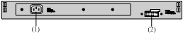
|
(1) AC input |
(2) DC output |
Figure 2 Rear panel of the RPS500-A3
2.5 LEDs
Table 2 LED description
|
LED |
Mark on panel |
Status |
Meaning |
|
PWR LED |
PWR |
On |
The RPS operates normally. |
|
Off |
The RPS fails. |
2.6 Technical Specifications
Table 3 Technical specifications of the RPS500-A3
|
Item |
Specifications |
|
|
Dimensions (H × W × D) |
44 × 441 × 165 mm (1.73 × 17.36 × 7.17 in.) |
|
|
Weight |
< 3.5 kg (<7.72 lb.) |
|
|
Input |
100 to 240 VAC, 50/60 Hz |
|
|
Available Outputs |
l –50 V/7.5 A l +12 V/10.5 A |
|
|
Maximum power consumption |
+12 V output only |
125 W |
|
–50 V output only |
375 W |
|
|
+12 V and –50 V outputs simultaneously |
l 125 W for +12 V output l 375 W for –50 V output l Total: < 500 W |
|
|
Operating temperature |
0℃ to 45℃ (32℉ to 113℉) |
|
|
Operating relative humidity |
10% to 90% (non-condensing) |
|
Note:
The design of this product complies with environmental protection requirements. Be sure to observe the relevant local laws and regulations when storing, using or disposing of this product.
3 Installation
3.1 Precautions
To avoid any device impairment or bodily injury because of improper use, follow the precautions listed below:
l Do not place the RPS unit on an unstable case or tabletop, and ensure that the cabinet and the workbench are firm enough to support the RPS unit and its accessories.
l Make sure that the ventilation and heat dissipation systems of the cabinet and the table-top are good. Make sure that enough room is left around the air intake and outlet of the RPS unit to allow good heat dissipation.
l This RPS unit is designed for indoor use only. Make sure that the temperature in the equipment room is within the range of 0℃ to 45℃ (32℉ to 113℉), and the humidity within the range of 10% to 90%.
l Keep the RPS unit away from any heavy-duty radio transmitter, radar transmitter, and high-frequency devices working in high current. Take electromagnetic shielding measures if necessary.
l Use a single-phase three-wire power socket with a neutral point connector or a multi-functional power socket for computers. Make sure that the neutral point of the power source is well grounded.
l Make sure that the power source satisfies the voltage requirement of the RPS unit.
l Interface cables must be routed indoors. Otherwise, over-voltage and over-current may damage the device. As for power cables from the outside of the building, you may add a dedicated lightening arrester at the input end of the cable.
l To enhance lightening protection, you may need to add a power lightening arrester at the input end.
l Wear an ESD-preventive wrist strap when installing the RPS unit, and make sure that the wrist strap has good skin contact.
l To avoid electric shock, NEVER open the chassis of the RPS unit while it is in operation; try not to open the RPS unit even if it is not electrified.
l Unplug the power cord before cleaning the RPS unit.
l Keep the equipment room clean. The limits on the concentrations of dust and harmful gases in the equipment room are shown in the following tables:
Table 4 Limit on dust concentration
|
Mechanical active material |
Limit (particles/m³) |
|
Dust particles |
≤ 3 × 10⁴ (No visible dust on tabletop over three days) |
|
Note: Dust particle size ≥ 5µm |
|
Table 5 Limits on harmful gas concentration
|
Gas |
Limit (mg/m3) |
|
SO2 |
0.2 |
|
H2S |
0.006 |
|
NH3 |
0.05 |
|
Cl2 |
0.01 |
3.2 Installing the RPS Unit
The RPS500-A3 can be installed either in a 19-inch standard rack or directly on a tabletop.
3.2.1 Installing the RPS Unit to a 19-inch Rack
Caution:
The front mounting ears are used only for fixing the RPS unit to the rack; they cannot bear the weight of the RPS unit. When installing the RPS500-A3 to a 19-inch rack, be sure to use a tray or bracket to support the weight of the unit.
Step 1: Put on an ESD-preventive wrist strap and check the grounding and stableness of the rack.
Step 2: Fix the supporting tray supplied with the rack horizontally at the appropriate position of the rack.
Step 3: Attach the front ears to the front end of the RPS unit using screws, as shown in Figure 3 .
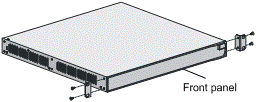
Figure 3 Install the RPS unit to a 19-inch rack (1)
Step 4: Place the RPS unit horizontally on the supporting tray, gently push the unit into the rack along the supporting tray, and fix the mounting ears to the front square-holed brackets of the rack with screws and cage nuts, as shown in Figure 4 .
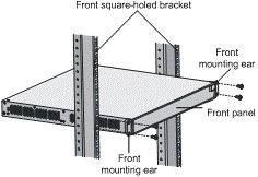
Figure 4 Install the RPS unit to a 19-inch rack (2)
3.2.2 Installing the RPS Unit on a Tabletop
If a 19-inch standard rack is not available, you can place the RPS unit directly on a clean, stable tabletop.
Follow these steps to install the RPS unit on a tabletop:
Step 1: Cautiously turn the RPS unit upside down. Then, use a piece of dry, soft cloth to remove any oil stain or dust from the dents on the bottom of the chassis.
Step 2: Peel off the stickers on the supplied foot pads and paste the foot pads into the dents on the chassis bottom.
Step 3: Turn over the RPS unit and place it on the tabletop. Verify the stableness and good grounding of the table.
3.3 Connecting the RPS Unit to the Powered Device
The RPS500-A3 can be used as a redundant backup power supply unit for multiple switch and router models. The following describes how to connect the RPS unit to a switch.
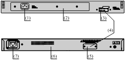
|
(1) RPS AC input |
(2) RPS rear panel |
|
(3) RPS DC output |
(4) DC power cable (optional) |
|
(5) Switch redundant power supply input |
|
|
(6) Switch rear panel |
(7) Switch AC input |
Figure 5 Connect the RPS unit to a switch
Step 1: Check that the power source to the RPS unit is disconnected.
Step 2: Remove the blank panel covering the redundancy power supply input of the switch.
Step 3: Plug one end of the RPS DC output cable into the redundant power supply socket on the rear panel of the switch and the other end into the DC output socket of the RPS unit.
Step 4: Connect the AC power source to the RPS unit.
Step 5: Check that the PWR LED on the front panel of the RPS unit lights up.
