| Title | Size | Downloads |
|---|---|---|
| H3C S7508E-X Switch Series Software Upgrade Guide-6W101-book.pdf | 297.32 KB |
- Table of Contents
|
|
CAUTION: Upgrade software only when necessary and under the guidance of a technical support engineer. |
Files used for upgrade
BootWare images
BootWare images are used to upgrade the BootWare program of cards, including the main processing units (MPUs), line processing units (LPUs), and switching fabric modules. The BootWare image comprises a basic section and an extended section.
|
|
NOTE: Generally, there is no need to upgrade the BootWare program independently. The device uses the shipped BootWare program. If a separate upgrade is required, do that under the guidance of an H3C technical support engineer. |
System software images
System software images are used at switch startup. The S7508E-X switch supports three types of system software images:
· Main system software image: Used by default.
· Backup system software image: Used when the main system software image is invalid or does not exist.
· Secure system software image: Used when the backup system software image is invalid or does not exist. If the secure system software image is also invalid, the switch displays a failure prompt.
A system software image is an .bin file such as main.bin.
Patch files
Patches for the S7508E-X switches are released in a patch package file.
A patch package file fixes certain software defects. It contains patch files for multiple cards. It enables you to use one command to bulk-fix bugs for multiple cards.
A patch package file corresponds to the system software image version. A patch package file can only fix defects of the corresponding system software image file, but does not add or delete any functions..
Upgrade methods
You can upgrade switch software by using one of the following methods:
|
Upgrade mode |
Object |
Remarks |
|
· BootWare · System software |
· Reboot the switch to make the upgrade effective. · This method interrupts services. |
|
|
Patches |
This method does not interrupt services, and fixes the target system software only. |
|
|
· BootWare · System software |
This method can be used when the switch cannot start up. |
|
|
NOTE: · The S7508E-X switch supports In-Service Software Upgrade (ISSU). ISSU can avoid service interruption during software upgrade. For more information about ISSU, see Fundamentals Configuration Guide in H3C S7500E[S7508E-X] Configuration Guides. · To make sure the active and standby MPUs use the same software version, upgrade them by using the same method. · Make sure that the system software and BootWare are compatible. For the compatibility between the system software and BootWare, see the hardware and software compatibility matrix in the Release Notes. · You can upgrade the BootWare for the LPUs and switching fabric modules from the CLI only. · The command outputs in this document are for reference only. |
Upgrade from the CLI
The upgrade procedure on a standalone switch is different from that on an Intelligent Resilient Framework (IRF) fabric. This section describes the following topics:
· Upgrading a standalone switch
|
|
NOTE: S7508E-X switches can form a single IRF fabric. For more information about IRF, see the IRF Configuration Guide in the H3C S7500E[S7508E-X] Configuration Guides. |
Upgrading a standalone switch
Upgrade prerequisites
# Telnet to the switch or log in through the console port.
# Display device information.
<Sysname> display device
Slot No. Brd Type Brd Status Subslot Num Sft Ver Patch Ver
0 LSQ1GP48SC Normal 0 S7508E-X P001
1 LSQ1GP48SC Normal 0 S7508E-X P001
2 NONE Absent 0 NONE None
3 NONE Absent 0 NONE None
4 LSQ1SUPA Master 0 S7508E-X P001
5 LSQ1SUPA Slave 0 S7508E-X P001
6 NONE Absent 0 NONE None
7 NONE Absent 0 NONE None
8 LSQ1GP48SC Normal 0 S7508E-X P001
9 LSQ1GP48SC Normal 0 S7508E-X P001
10 LSQ1FAB08A Absent 0 NONE None
11 NONE Absent 0 NONE None
12 NONE Absent 0 NONE None
13 NONE Absent 0 NONE None
The output shows that the switch has two MPUs, an active MPU in slot 4 and a standby MPU in slot 5. You must upgrade software for the two MPUs.
|
|
NOTE: You only need to upgrade the active MPU if the device has no standby MPU. |
# Examine the free storage space on the active and standby MPUs.
· On the active MPU
<Sysname> dir
Directory of flash:/
0 -rw- 31912384 May 23 2000 144:40:52 startup.bin
1 drw- - Apr 01 2000 23:55:57 seclog
2 -rw- 5582 Apr 12 2000 06:46:17 startup.cfg
3 -rw- 4866 Apr 11 2000 19:04:33 system.xml
4 -rw- 31911744 Apr 06 2000 17:23:33 S7508E-X.bin
5 -rw- 9176 Apr 11 2000 17:44:02 patch.bin
6 -rw- 1526 Apr 02 2000 01:02:50 patchstate
7 drw- - Apr 11 2000 18:57:42 test
8 -rw- 118773 Apr 11 2000 21:17:30 logfile.log
9 drw- - Apr 02 2000 03:06:40 cd
125349 KB total (62857 KB free)
· On the standby MPU
<Sysname> dir slot5#flash:/
Directory of slot5#flash:/
0 -rw- 31912384 May 23 2000 144:40:52 startup.bin
1 drw- - Apr 01 2000 23:55:57 seclog
2 -rw- 5582 Apr 12 2000 06:46:17 startup.cfg
3 -rw- 4866 Apr 11 2000 19:04:33 system.xml
4 -rw- 31911744 Apr 06 2000 17:23:33 S7508E-X.bin
5 -rw- 9176 Apr 11 2000 17:44:02 patch.bin
6 -rw- 1526 Apr 02 2000 01:02:50 patchstate
7 drw- - Apr 11 2000 18:57:42 test
8 -rw- 118773 Apr 11 2000 21:17:30 logfile.log
9 drw- - Apr 02 2000 03:06:40 cd
125349 KB total (62857 KB free)
Verify that the free storage space is sufficient for the files used for upgrade. You can delete undesired files with the delete /unreserved command to free storage space.
# Delete undesired files from the active and standby MPUs.
· On the active MPU
<Sysname> delete /unreserved flash:/S7508E-X.bin
The contents cannot be restored!!! Delete flash:/S7508E-X.bin?[Y/N]:y
Deleting a file permanently will take a long time. Please wait...
..................................................
%Delete file flash:/S7508E-X.bin...Done.
· On the standby MPU
<Sysname> delete /unreserved slot5#flash:/S7508E-X.bin
The contents cannot be restored!!! Delete slot5#flash:/S7508E-X.bin?[Y/N]:y
Deleting a file permanently will take a long time. Please wait...
..................................................
%Delete file slot5#flash:/S7508E-X.bin...Done.
|
|
NOTE: · The delete /unreserved file-url command deletes a file permanently and the action cannot be undone. · The delete file-url command moves a file to the recycle bin and the file still occupies storage space. To permanently delete the file from the recycle bin, execute the reset recycle-bin command in the original directory of the file. |
Downloading files to the switch
|
|
NOTE: · Download the files used for upgrade to the flash memory of the active MPU and the standby MPU. Skip this section if the files are already located there. · The following example shows how to download a system software image (a .bin file) to the switch. Download other files in the same way as needed. |
You can download the .bin file through FTP or TFTP. The following illustrates how to download through FTP when the switch serves as the FTP client and a PC serves as the FTP server. Make sure the FTP client and server can reach other.
1. Run the FTP server program on the PC (assume its IP address is 10.10.110.1) and set the username, password, and directory where the .bin file is saved.
|
|
CAUTION: S7508E-X switches are not shipped with FTP server software. Prepare it by yourself. |
2. Download the .bin file (newest.bin for example) to the active MPU of the switch.
# Log in to the PC through FTP.
<Sysname> ftp 10.10.110.1
Trying 10.10.110.1...
Press CTRL+K to abort
Connected to 10.10.110.1
220 FTP service ready.
User(10.10.110.1:(none)):username ---Type the username
331 Password required for username.
Password: ---Type the password
230 User logged in
# Set the file transfer mode to binary.
[ftp] binary
200 Type set to I.
# Download the .bin file from the PC to the root directory of the storage medium on the active MPU.
[ftp] get newest.bin
227 Entering Passive Mode (10,10,110,1,17,97).
125 BINARY mode data connection already open, transfer starting for /newest.bin
226 Transfer complete.
FTP: 28945856 byte(s) received in 35.974 second(s), 896.00K byte(s)/sec.
[ftp] bye
221 Server closing.
3. Copy the .bin file to the standby MPU of the switch.
# Copy the file newest.bin to the root directory of the storage medium on the standby MPU in slot 5.
<Sysname> copy newest.bin slot5#flash:/
Copy flash:/newest.bin to slot5#flash:/newest.bin?[Y/N]:y
%Copy file flash:/newest.bin to slot5#flash:/newest.bin...Done.
|
|
NOTE: You can configure the switch as the FTP server, FTP client, or TFTP client. The transfer procedures slightly vary. For more information about FTP and TFTP, see the Fundamentals Configuration Guide in the H3C S7500E[S7508E-X] Configuration Guides. |
Upgrading software from the CLI
|
|
CAUTION: Make sure the BootWare image, system software image, or patch package used for upgrade have been saved in the root directory of the storage medium of the active MPU and the standby MPU. |
Perform the following tasks as needed:
1. Upgrade BootWare
The following example uses mpu.btw, lpu.btw, and lpo.btw files to upgrade the BootWare of MPUs, LPUs, switching fabric modules respectively.
|
|
NOTE: The BootWare image stored on the active MPU can be used to upgrade the active MPU, LPUs, and switching fabric modules while that stored on the standby MPU is used to upgrade the standby MPU only. |
# Upgrade the BootWare for the active MPU in slot 4.
<Sysname> bootrom update file flash:/mpu.btw slot 4
This command will update bootrom file on the specified board(s),
Continue? [Y/N]:y
Now updating bootrom, please wait...
Start accessing bootflash chip...
Bootrom update succeeded in slot 4.
# Upgrade the BootWare for the standby MPU in slot 5.
<Sysname> bootrom update file slot5#flash:/mpu.btw slot 5
This command will update bootrom file on the specified board(s),
Continue? [Y/N]:y
Now updating bootrom, please wait...
Start accessing bootflash chip...
Bootrom update succeeded in slot 5.
# Upgrade the BootWare for the LPU in slot 0 (upgrade other LPUs in the same way).
<Sysname> bootrom update file flash:/lpu.btw slot 0
This command will update bootrom file on the specified board(s),
Continue? [Y/N]:y
Now updating bootrom, please wait...
Board has finished loading file on Chassis 0 Slot 0.
Start accessing bootflash chip...
Bootrom update succeeded in slot 0.
# Upgrade the BootWare for the switching fabric module in slot 10.
<Sysname> bootrom update file flash:/lpo.btw slot 10
This command will update bootrom file on the specified board(s),
Continue? [Y/N]:y
Now updating bootrom, please wait...
Board has finished loading file on Chassis 0 Slot 10.
Start accessing bootflash chip...
Bootrom update succeeded in slot 10.
# Reboot the switch to validate the upgrade.
<Sysname> reboot
Start to check configuration with next startup configuration file, please wait.
........DONE!
This command will reboot the device. Continue? [Y/N]:y
Reboot device by command.
# Specify the file newest.bin as the main system software image to be used at the next startup of the active MPU in slot 4.
<Sysname> boot-loader file flash:/newest.bin slot 4 main
This command will set the boot file of the specified board. Continue? [Y/N]:y
The specified file will be used as the main boot file at the next reboot on slot 4!
# Specify the file newest.bin as the main system software image to be used at the next startup of the standby MPU in slot 5.
<Sysname> boot-loader file slot5#flash:/newest.bin slot 5 main
This command will set the boot file of the specified board. Continue? [Y/N]:y
The specified file will be used as the main boot file at the next reboot on slot 5!
# Reboot the switch to validate the upgrade.
<Sysname> reboot
Start to check configuration with next startup configuration file, please wait.
........DONE!
This command will reboot the device. Continue? [Y/N]:y
Reboot device by command.
|
|
CAUTION: · To prevent configuration loss, save the latest configuration changes before you reboot the switch. · For more information about the boot-loader command, see the Fundamentals Command Reference in the H3C S7500E[S7508E-X] Command References. |
3. Install the patch package
# Install the patch package S7508xR6820Patch001.bin, and configure the device to continue the installation after reboot.
<Sysname> system-view
[Sysname] patch install file S7508xR6820Patch001.bin
Patches will be installed. Continue? [Y/N]:y
Do you want to run patches after reboot? [Y/N]:y
Installing patches…
|
|
NOTE: If a patch package was installed before, you must uninstall it before you can install the new one. To view patch information, use the display patch information command. For details about patch installation, see Fundamentals Configuration Guide in the H3C S7500E[S7508E-X] Configuration Guides. |
Upgrading an IRF fabric
Upgrade prerequisites
# Telnet to the switch or log in through the console port.
# Display device information.
<Sysname>display device
Chassis Slot Type State Subslot Soft Ver Patch Ver
1 0 LSQ1GP48SC Normal 0 S7508E-X P001
1 1 LSQ1GP48SC Normal 0 S7508E-X P001
1 2 NONE Absent 0 NONE None
1 3 NONE Absent 0 NONE None
1 4 LSQ1SUPA Master 0 S7508E-X P001
1 5 LSQ1SUPA Slave 0 S7508E-X P001
1 6 NONE Absent 0 NONE None
1 7 NONE Absent 0 NONE None
1 8 LSQ1TGX4SD Normal 0 S7508E-X P001
1 9 LSQ1GP48SC Normal 0 S7508E-X P001
1 10 LSQ1FAB08A Absent 0 NONE None
1 11 NONE Absent 0 NONE None
1 12 NONE Absent 0 NONE None
1 13 NONE Absent 0 NONE None
2 0 LSQ1GP48SC Normal 0 S7508E-X P001
2 1 LSQ1GP48SC Normal 0 S7508E-X P001
2 2 NONE Absent 0 NONE None
2 3 NONE Absent 0 NONE None
2 4 LSQ1SUPA Slave 0 S7508E-X P001
2 5 LSQ1SUPA Slave 0 S7508E-X P001
2 6 NONE Absent 0 NONE None
2 7 NONE Absent 0 NONE None
2 8 LSQ1TGX4SD Normal 0 S7508E-X P001
2 9 LSQ1GP48SC Normal 0 S7508E-X P001
2 10 LSQ1FAB08A Absent 0 NONE None
2 11 NONE Absent 0 NONE None
2 12 NONE Absent 0 NONE None
2 13 NONE Absent 0 NONE None
The output shows that two switches form an IRF fabric. The following table shows the MPU information.
Table 1 MPU information of the IRF fabric
|
MPU |
Member ID |
Slot number |
|
Active MPU of the IRF fabric |
1 |
4 |
|
Standby MPU of the IRF fabric |
1 |
5 |
|
Standby MPU of the IRF fabric |
2 |
4 |
|
Standby MPU of the IRF fabric |
2 |
5 |
# Check the free storage space of the active and standby MPUs on the IRF fabric.
· On the active MPU of the IRF fabric
<Sysname> dir
Directory of flash:/
0 -rw- 31912384 May 23 2000 144:40:52 startup.bin
1 drw- - Apr 01 2000 23:55:57 seclog
2 -rw- 5582 Apr 12 2000 06:46:17 startup.cfg
3 -rw- 4866 Apr 11 2000 19:04:33 system.xml
4 -rw- 31911744 Apr 06 2000 17:23:33 S7508E-X.bin
5 -rw- 9176 Apr 11 2000 17:44:02 patch.bin
6 -rw- 1526 Apr 02 2000 01:02:50 patchstate
7 drw- - Apr 11 2000 18:57:42 test
8 -rw- 118773 Apr 11 2000 21:17:30 logfile.log
9 drw- - Apr 02 2000 03:06:40 cd
125349 KB total (62857 KB free)
· On the standby MPU in slot 5 of member device 1
<Sysname> dir chassis1#slot5#flash:/
Directory of chassis1#slot5#flash:/
0 -rw- 31912384 May 23 2000 144:40:52 startup.bin
1 drw- - Apr 01 2000 23:55:57 seclog
2 -rw- 5582 Apr 12 2000 06:46:17 startup.cfg
3 -rw- 4866 Apr 11 2000 19:04:33 system.xml
4 -rw- 31911744 Apr 06 2000 17:23:33 S7508E-X.bin
5 -rw- 9176 Apr 11 2000 17:44:02 patch.bin
6 -rw- 1526 Apr 02 2000 01:02:50 patchstate
7 drw- - Apr 11 2000 18:57:42 test
8 -rw- 118773 Apr 11 2000 21:17:30 logfile.log
9 drw- - Apr 02 2000 03:06:40 cd
125349 KB total (62857 KB free)
· On the standby MPU in slot 4 of member device 2
<Sysname> dir chassis2#slot4#flash:/
Directory of chassis2#slot4#flash:/
0 -rw- 31912384 May 23 2000 144:40:52 startup.bin
1 drw- - Apr 01 2000 23:55:57 seclog
2 -rw- 5582 Apr 12 2000 06:46:17 startup.cfg
3 -rw- 4866 Apr 11 2000 19:04:33 system.xml
4 -rw- 31911744 Apr 06 2000 17:23:33 S7508E-X.bin
5 -rw- 9176 Apr 11 2000 17:44:02 patch.bin
6 -rw- 1526 Apr 02 2000 01:02:50 patchstate
7 drw- - Apr 11 2000 18:57:42 test
8 -rw- 118773 Apr 11 2000 21:17:30 logfile.log
9 drw- - Apr 02 2000 03:06:40 cd
125349 KB total (62857 KB free)
· On the standby MPU in slot 5 of member device 2
<Sysname> dir chassis2#slot5#flash:/
Directory of chassis2#slot5#flash:/
0 -rw- 31912384 May 23 2000 144:40:52 startup.bin
1 drw- - Apr 01 2000 23:55:57 seclog
2 -rw- 5582 Apr 12 2000 06:46:17 startup.cfg
3 -rw- 4866 Apr 11 2000 19:04:33 system.xml
4 -rw- 31911744 Apr 06 2000 17:23:33 S7508E-X.bin
5 -rw- 9176 Apr 11 2000 17:44:02 patch.bin
6 -rw- 1526 Apr 02 2000 01:02:50 patchstate
7 drw- - Apr 11 2000 18:57:42 test
8 -rw- 118773 Apr 11 2000 21:17:30 logfile.log
9 drw- - Apr 02 2000 03:06:40 cd
125349 KB total (62857 KB free)
Verify that the free storage space is sufficient for the files to be downloaded. You can delete undesired files with the delete /unreserved command to free storage space.
# Delete undesired files from the active and standby MPUs of the IRF fabric.
· On the active MPU of the IRF fabric
<Sysname> delete /unreserved flash:/S7508E-X.bin
The contents cannot be restored!!! Delete flash:/S7508E-X.bin?[Y/N]:y
Deleting a file permanently will take a long time. Please wait...
..................................................
%Delete file flash:/S7508E-X.bin...Done.
· On the standby MPU in slot 5 of member device 1 (delete undesired files on other standby MPUs in the same way)
<Sysname> delete /unreserved chassis1#slot5#flash:/S7508E-X.bin
The contents cannot be restored!!! Delete chassis1#slot5#flash:/S7508E-X.bin?[Y/N]:y
Deleting a file permanently will take a long time. Please wait...
..................................................
%Delete file chassis1#slot5#flash:/S7508E-X.bin...Done.
|
|
NOTE: · The delete /unreserved file-url command deletes a file permanently and the action cannot be undone. · The delete file-url command moves a file to the recycle bin and the file still occupies storage space. To permanently delete the file from the recycle bin, execute the reset recycle-bin command in the original directory of the file. |
Downloading files to the IRF fabric
|
|
NOTE: · Download the files used for upgrade to the flash memory of the active MPU and the standby MPU. Skip this section if the files are already located there. · The following example shows how to download a .bin file to the IRF fabric. Download other files in the same way as needed. |
You can download the .bin file through FTP or TFTP. The following illustrates how to download through FTP when the switch serves as the FTP client and a PC serves as the FTP server. Make sure the FTP client and server can reach other.
1. Run the FTP server program on the PC (assume its IP address is 10.10.110.1) and set the username, password, and directory where the .bin file is saved.
|
|
CAUTION: S7508E-X switches are not shipped with FTP server software. Prepare it by yourself. |
2. Download the .bin file (newest.bin for example) to the active MPU of the IRF fabric.
# Log in to the PC through FTP.
<Sysname> ftp 10.10.110.1
Trying 10.10.110.1...
Press CTRL+K to abort
Connected to 10.10.110.1
220 FTP service ready.
User(10.10.110.1:(none)):username --- Type the username
331 Password required for username.
Password: --- Type the password
230 User logged in
# Set the file transfer mode to binary.
[ftp] binary
200 Type set to I.
# Download the .bin file from the PC to the root directory of the storage medium on the active MPU of the IRF fabric.
[ftp] get newest.bin
227 Entering Passive Mode (10,10,110,1,17,97).
125 BINARY mode data connection already open, transfer starting for /newest.bin.
226 Transfer complete.
FTP: 28945856 byte(s) received in 35.974 second(s), 896.00K byte(s)/sec.
[ftp] bye
221 Server closing.
3. Copy the file newest.bin to the root directory of the storage medium on each standby MPU of the IRF fabric.
· On the standby MPU in slot 5 of member device 1
<Sysname> copy newest.bin chassis1#slot5#flash:/
Copy flash:/newest.bin to chassis1#slot5#flash:/newest.bin?[Y/N]:y
%Copy file flash:/newest.bin to chassis1#slot5#flash:/newest.bin...Done.
· On the standby MPU in slot 4 of member device 2
<Sysname> copy newest.bin chassis2#slot4#flash:/
Copy flash:/newest.bin to chassis2#slot4#flash:/newest.bin?[Y/N]:y
%Copy file flash:/newest.bin to chassis2#slot4#flash:/newest.bin...Done.
· On the standby MPU in slot 5 of member device 2
<Sysname> copy newest.bin chassis2#slot5#flash:/
Copy flash:/newest.bin to chassis2#slot5#flash:/newest.bin?[Y/N]:y
%Copy file flash:/newest.bin to chassis2#slot5#flash:/newest.bin...Done.
|
|
NOTE: You can configure the switch as the FTP server, FTP client, or TFTP client. The transfer processes slightly vary. For more information about FTP and TFTP, see the Fundamentals Configuration Guide in the H3C S7500E[S7508E-X] Configuration Guides. |
Upgrading software from the CLI
|
|
NOTE: Make sure all the files used for upgrade exit in the root directory of the storage medium of the active and standby MPUs of the IRF fabric. |
Perform the following tasks as needed:
1. Upgrade BootWare
The following example uses mpu.btw, lpu.btw, and lpo.btw files to upgrade the BootWare of MPUs, LPUs, switching fabric modules respectively.
|
|
NOTE: The BootWare image stored on the active MPU can be used to upgrade the active MPU, LPUs, and switching fabric modules while that stored on a standby MPU is used to upgrade the standby MPU only. |
# Upgrade the BootWare for the active MPU.
<Sysname> bootrom update file flash:/mpu.btw chassis 1 slot 4
This command will update bootrom file on the specified board(s),
Continue? [Y/N]:y
Now updating bootrom, please wait...
Start accessing bootflash chip...
Bootrom update succeeded in chassis 1 slot 4.
# Upgrade the BootWare of the standby MPU in slot 5 of member device 1 (upgrade other standby MPUs in the same way).
<Sysname>bootrom update file chassis1#slot5#flash:/mpu.btw chassis 1 slot 5
This command will update bootrom file on the specified board(s), Continue? [Y/N]:y
Now updating bootrom, please wait...
Start accessing bootflash chip...
Bootrom update succeeded in chassis 1 slot 5.
# Upgrade the BootWare of the LPU in slot 0 of member device 2 (upgrade other LPUs in the same way).
<Sysname>bootrom update file flash:/lpu.btw chassis 2 slot 0
This command will update bootrom file on the specified board(s), Continue? [Y/N]:y
Now updating bootrom, please wait...
Start accessing bootflash chip...
Bootrom update succeeded in chassis 2 slot 0.
# Upgrade the BootWare of the switching fabric module in slot 10 of member device 2. (upgrade other switching fabric modules in the same way).
<Sysname>bootrom update file flash:/lpo.btw chassis 2 slot 10
This command will update bootrom file on the specified board(s), Continue? [Y/N]:y
Now updating bootrom, please wait...
Start accessing bootflash chip...
Bootrom update succeeded in chassis 2 slot 10.
# Reboot the IRF fabric to validate the upgrade.
<Sysname> reboot
Start to check configuration with next startup configuration file, please wait.
........DONE!
This command will reboot the device. Continue? [Y/N]:y
Reboot device by command.
# Specify the file newest.bin as the main system software image to be used at the next startup of the active MPU of the IRF fabric.
<Sysname> boot-loader file newest.bin chassis 1 slot 4 main
This command will set the boot file of the specified board. Continue? [Y/N]:y
The specified file will be used as the main boot file at the next reboot on chassis 1 slot 4!
# Specify the file newest.bin as the main system software image to be used at the next startup of the standby MPUs of the IRF fabric.
· On the standby MPU in slot 5 of member device 1
<Sysname> boot-loader file chassis1#slot5#flash:/newest.bin chassis 1 slot 5 main
This command will set the boot file of the specified board. Continue? [Y/N]:y
The specified file will be used as the main boot file at the next reboot on chassis 1 slot 5!
· On the standby MPU in slot 4 of member device 2
<Sysname> boot-loader file chassis2#slot4#flash:/newest.bin chassis 2 slot 4 main
This command will set the boot file of the specified board. Continue? [Y/N]:y
The specified file will be used as the main boot file at the next reboot on chassis 2 slot 4!
· On the standby MPU in slot 5 of member device 2
<Sysname> boot-loader file chassis2#slot5#flash:/newest.bin chassis 2 slot 5 main
This command will set the boot file of the specified board. Continue? [Y/N]:y
The specified file will be used as the main boot file at the next reboot on chassis 2 slot 5!
# Reboot the IRF fabric to validate the upgrade.
<Sysname> reboot
Start to check configuration with next startup configuration file, please wait.
........DONE!
This command will reboot the device. Continue? [Y/N]:y
Reboot device by command.
|
|
CAUTION: · To prevent configuration loss, save the latest configuration changes before you reboot the switch. · For more information about the boot-loader command, see the Fundamentals Command Reference in the H3C S7500E[S7508E-X] Command References. |
3. Install the patch package
# Install the patch package S7508xR6820Patch001.bin, and configure the device to continue the installation after reboot.
<Sysname> system-view
[Sysname] patch install file S7508xR6820Patch001.bin
Patches will be installed. Continue? [Y/N]:y
Do you want to run patches after reboot? [Y/N]:y
Installing patches…
|
|
NOTE: If a patch package was installed before, you must uninstall it before you can install the new one. To view patch information, use the display patch information command. For details about patch installation, see the Fundamentals Configuration Guide in the H3C S7500E[S7508E-X] Configuration Guides. |
Upgrade from the BootWare menu
|
|
CAUTION: You cannot simultaneously upgrade the active and standby MPUs from the BootWare menu. To make sure the active and standby MPUs use the same software version, upgrade them in turn. |
BootWare menu
Connect a configuration terminal such as a PC to the console port of the switch with a console cable, run the terminal emulation program on the PC, and power on the switch.
Upon power-on, the switch runs the BootWare program and displays the following information:
System is starting...
Booting Normal Extend BootWare.
The Extend BootWare is self-decompressing...................................
.....Done!
****************************************************************************
* *
* BootWare, Version 1.00 *
* *
****************************************************************************
Compiled Date : Jul 1 2010
CPU Type : XLS408
CPU L1 Cache : 32KB
CPU Clock Speed : 1000MHz
Memory Type : DDR2 SDRAM
Memory Size : 1024MB
Memory Speed : 533MHz
BootWare Size : 508KB
Flash Size : 128MB
BASIC CPLD Version : 3.0
EXTEND CPLD Version : 3.0
PCB Version : Ver.A
BootWare Validating...
Press Ctrl+B to enter extended boot menu...2
|
|
NOTE: · To enter the BootWare menu, press Ctrl+B within 5 seconds when "Press Ctrl+B to enter BootWare menu..." appears. If you fail to do so, restart the switch and try again. · The output varies with switch models. |
Press Ctrl+B. The system prompts you to enter the BootWare password:
Please input BootWare password:
Enter the password, and press Enter. The BootWare menu appears. (By default, no password is set, and you can directly press Enter to enter the BootWare menu.)
|
|
CAUTION: · Keep in mind the BootWare password. · If you fail to provide the correct password three times, you have to reboot the switch to enter the password again. |
Note: The current operating device is flash
Enter < Storage Device Operation > to select device.
===========================<EXTEND-BOOTWARE MENU>===========================
|<1> Boot System |
|<2> Enter Serial SubMenu |
|<3> Enter Ethernet SubMenu |
|<4> File Control |
|<5> Modify BootWare Password |
|<6> Skip Current System Configuration |
|<7> BootWare Operation Menu |
|<8> Clear Super Password |
|<9> Storage Device Operation |
|<0> Reboot |
============================================================================
Enter your choice(0-9):
Upgrading system software
Upgrade system software by using one of the following methods:
· Using TFTP through the management Ethernet port
· Using FTP through the management Ethernet port
· Using Xmodem through the console port
Using TFTP through the management Ethernet port
Step1 Connect the management Ethernet port of the switch to the PC that stores the target .bin file (the IP address of the PC is required), and connect the console port of the switch to the same or another PC.
Step2 Run the TFTP server program on the PC connected to the management Ethernet port and specify the file storage directory.
|
|
NOTE: S7508E-X switches are not shipped with TFTP server software. Prepare it by yourself. |
Step3 Run the terminal emulation program on the PC connected to the console port. Start the switch, enter the BootWare menu (see BootWare menu for more information), and type 3 when you see "Enter your choice(0-9):" to enter the Ethernet submenu.
==========================<Enter Ethernet SubMenu>==========================
|Note:the operating device is flash |
|<1> Download Application Program To SDRAM And Run |
|<2> Update Main Application File |
|<3> Update Backup Application File |
|<4> Update Secure Application File |
|<5> Modify Ethernet Parameter |
|<0> Exit To Main Menu |
|<Ensure The Parameter Be Modified Before Downloading!> |
============================================================================
Enter your choice(0-5):
Step4 Type 5 to set Ethernet port parameters.
|
|
NOTE: · If no parameters are set, pressing Enter adopts the default settings. · You only need to configure settings under <CORE 0 ETHERNET PARAMETER SET>. Settings under <CORE 1 ETHERNET PARAMETER SET> do not affect software upgrade. |
======================<CORE 0 ETHERNET PARAMETER SET>=======================
|Note: '.' = Clear field. |
| '-' = Go to previous field. |
| Ctrl+D = Quit. |
============================================================================
Protocol (FTP or TFTP):tftp
Load File Name :test.bin
:main.bin
Target File Name :test.bin
:main.bin
Server IP Address :192.168.80.22
Local IP Address :192.168.80.10
Gateway IP Address :0.0.0.0
======================<CORE 1 ETHERNET PARAMETER SET>=======================
|Note: '.' = Clear field. |
| '-' = Go to previous field. |
| Ctrl+D = Quit. |
============================================================================
Protocol (FTP or TFTP) :tftp
Load File Name :test.bin
:main.bin
Target File Name :test.bin
:main.bin
Server IP Address :192.168.80.22
Local IP Address :192.168.80.10
Gateway IP Address :0.0.0.0
Table 2 Output description
|
Field |
Description |
|
Load File Name |
Name of the file to be downloaded |
|
Target File Name |
Name of the file downloaded to the switch, which must have the same suffix as the file to be downloaded |
|
Gateway IP Address |
Needed when the client and server reside on different subnets |
Step5 After you set TFTP parameters, the system returns to the Ethernet submenu.
==========================<Enter Ethernet SubMenu>==========================
|Note:the operating device is flash |
|<1> Download Application Program To SDRAM And Run |
|<2> Update Main Application File |
|<3> Update Backup Application File |
|<4> Update Secure Application File |
|<5> Modify Ethernet Parameter |
|<0> Exit To Main Menu |
|<Ensure The Parameter Be Modified Before Downloading!> |
============================================================================
Enter your choice(0-5):
Step6 Type a number from 2 to 4 as needed. For example, type 2 to update the main system software image. The following information appears.
Loading.....................................................................
............................................................................
.........................Done!
31911744 bytes downloaded!
Updating File flash:/main.bin...............................................
....................................................Done!
==========================<Enter Ethernet SubMenu>==========================
|Note:the operating device is flash |
|<1> Download Application Program To SDRAM And Run |
|<2> Update Main Application File |
|<3> Update Backup Application File |
|<4> Update Secure Application File |
|<5> Modify Ethernet Parameter |
|<0> Exit To Main Menu |
|<Ensure The Parameter Be Modified Before Downloading!> |
============================================================================
Enter your choice(0-5):
Step7 Type 0 to return to the BooWare menu, and type 1 in the BootWare menu to boot the switch.
Using FTP through the management Ethernet port
Step1 Connect the management Ethernet port of the switch to the PC that stores the target .bin file (the IP address of the PC is required), and connect the console port of the switch to the same or another PC.
Step2 Run the FTP server program on the PC connected to the management Ethernet port, specify the file storage directory, and set the username and password.
|
|
NOTE: S7508E-X switches are not shipped with FTP server software. Prepare it by yourself. |
Step3 Run the terminal emulation program on the PC connected to the console port. Start the switch, enter the BootWare menu (see BootWare menu for more information), and press 3 when you see "Enter your choice(0-9):" to enter the Ethernet submenu.
==========================<Enter Ethernet SubMenu>==========================
|Note:the operating device is flash |
|<1> Download Application Program To SDRAM And Run |
|<2> Update Main Application File |
|<3> Update Backup Application File |
|<4> Update Secure Application File |
|<5> Modify Ethernet Parameter |
|<0> Exit To Main Menu |
|<Ensure The Parameter Be Modified Before Downloading!> |
============================================================================
Enter your choice(0-5):
Step4 Type 5 to set Ethernet port parameters.
|
|
NOTE: · If no parameters are set, pressing Enter adopts the default settings. · You only need to configure settings under <CORE 0 ETHERNET PARAMETER SET>. Settings under <CORE 1 ETHERNET PARAMETER SET> do not affect software upgrade. |
======================<CORE 0 ETHERNET PARAMETER SET>=======================
|Note: '.' = Clear field. |
| '-' = Go to previous field. |
| Ctrl+D = Quit. |
============================================================================
Protocol (FTP or TFTP):ftp
Load File Name :test.bin
:main.bin
Target File Name :test.bin
:main.bin
Server IP Address :192.168.80.20
Local IP Address :192.168.80.10
Gateway IP Address :0.0.0.0
FTP User Name :UserN
FTP User Password :PWD
======================<CORE 1 ETHERNET PARAMETER SET>=======================
|Note: '.' = Clear field. |
| '-' = Go to previous field. |
| Ctrl+D = Quit. |
============================================================================
Protocol (FTP or TFTP):ftp
Load File Name :test.bin
:main.bin
Target File Name :test.bin
:main.bin
Server IP Address :192.168.80.20
Local IP Address :192.168.80.10
Gateway IP Address :0.0.0.0
FTP User Name :UserN
FTP User Password :PWD
Table 3 Output description
|
Field |
Description |
|
Load File Name |
Name of the file to be downloaded |
|
Target File Name |
Name of the file downloaded to the switch, which must have the same suffix as the file to be downloaded |
|
Gateway IP Address |
Needed when the client and server reside on different subnets |
Step5 After you set FTP parameters, the system returns to the Ethernet submenu.
==========================<Enter Ethernet SubMenu>==========================
|Note:the operating device is flash |
|<1> Download Application Program To SDRAM And Run |
|<2> Update Main Application File |
|<3> Update Backup Application File |
|<4> Update Secure Application File |
|<5> Modify Ethernet Parameter |
|<0> Exit To Main Menu |
|<Ensure The Parameter Be Modified Before Downloading!> |
============================================================================
Enter your choice(0-5):
Step6 Type a number from 2 to 4 as needed. For example, type 2 to update the main system software image. The following information appears.
Loading.....................................................................
............................................................................
.........................Done!
31911744 bytes downloaded!
Updating File flash:/main.bin...............................................
....................................................Done!
==========================<Enter Ethernet SubMenu>==========================
|Note:the operating device is flash |
|<1> Download Application Program To SDRAM And Run |
|<2> Update Main Application File |
|<3> Update Backup Application File |
|<4> Update Secure Application File |
|<5> Modify Ethernet Parameter |
|<0> Exit To Main Menu |
|<Ensure The Parameter Be Modified Before Downloading!> |
============================================================================
Enter your choice(0-5):
Step7 Type 0 to return to the BooWare menu, and type 1 in the BootWare menu to boot the switch.
Using Xmodem through the console port
Step1 Connect the console port of the switch to the PC that stores the .bin file.
Step2 Run the terminal emulation program on the PC. Start the switch, enter the boot menu (see BootWare menu for more information), and type 2 when you see " Enter your choice(0-9):" to enter the serial submenu.
===========================<Enter Serial SubMenu>===========================
|Note:the operating device is flash |
|<1> Download Application Program To SDRAM And Run |
|<2> Update Main Application File |
|<3> Update Backup Application File |
|<4> Update Secure Application File |
|<5> Modify Serial Interface Parameter |
|<0> Exit To Main Menu |
============================================================================
Enter your choice(0-5):
Step3 Type 5. The baud rate set menu appears.
===============================<BAUDRATE SET>===============================
|Note:'*'indicates the current baudrate |
| Change The HyperTerminal's Baudrate Accordingly |
|---------------------------<Baudrate Available>---------------------------|
|<1> 9600(Default)* |
|<2> 19200 |
|<3> 38400 |
|<4> 57600 |
|<5> 115200 |
|<0> Exit |
============================================================================
Enter your choice(0-5):2
Step4 Select an appropriate download baud rate. For example, type 2 to select 19200 bps. The following information appears:
Baudrate has been changed to 19200 bps.
Please change the terminal's baudrate to 19200 bps, press ENTER when ready.
|
|
NOTE: If you select the baud rate of 9600 bps, directly go to Step 8. |
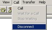
Step5 Disconnect the HyperTerminal from the switch by selecting Call/Disconnect in the HyperTerminal window.
Figure 1 Disconnect the terminal
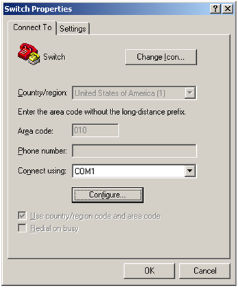
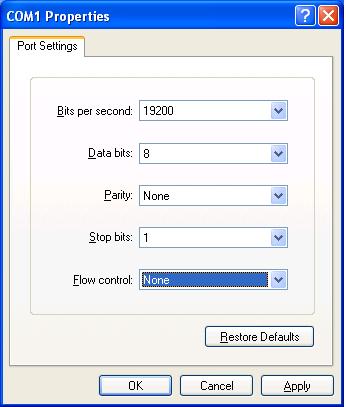
Step6 Select File > Properties in the HyperTerminal window, click Configure in the popup dialog box, and select the baud rate of 19200 bps in the console port properties dialog box.
Figure 2 Switch Properties dialog box
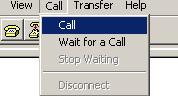
Step7 Click Call/Call to re-connect to the switch.
Figure 4 Connect to the switch
Press Enter, and the following information appears.
The current baudrate is 19200 bps
===============================<BAUDRATE SET>===============================
|Note:'*'indicates the current baudrate |
| Change The HyperTerminal's Baudrate Accordingly |
|---------------------------<Baudrate Available>---------------------------|
|<1> 9600(Default) |
|<2> 19200* |
|<3> 38400 |
|<4> 57600 |
|<5> 115200 |
|<0> Exit |
============================================================================
Enter your choice(0-5):
Step8 Type 0 to return to the serial submenu.
===========================<Enter Serial SubMenu>===========================
|Note:the operating device is flash |
|<1> Download Application Program To SDRAM And Run |
|<2> Update Main Application File |
|<3> Update Backup Application File |
|<4> Update Secure Application File |
|<5> Modify Serial Interface Parameter |
|<0> Exit To Main Menu |
============================================================================
Enter your choice(0-5):
Step9 Type a number from 2 to 4 as needed. For example, type 2 to update the main system software image. The following information appears.
Please Start To Transfer File, Press <Ctrl+C> To Exit.
Waiting ...CCCCC
Step10 Select Transfer > Send File in the HyperTerminal window. In the Send File dialog box that appears, click Browse to select the target .bin file, and select Xmodem as the protocol.
Figure 5 Send file dialog box
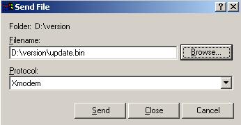
Step11 Click Send. The following dialog box appears:
Figure 6 Send the file using XMODEM
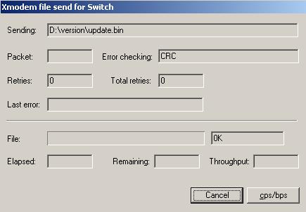
When the download is complete, the following information appears:
Download successfully!
31911808 bytes downloaded!
Input the File Name:update.bin
Updating File flash:/update.bin..............................................
.....................................................Done!
===========================<Enter Serial SubMenu>===========================
|Note:the operating device is flash |
|<1> Download Application Program To SDRAM And Run |
|<2> Update Main Application File |
|<3> Update Backup Application File |
|<4> Update Secure Application File |
|<5> Modify Serial Interface Parameter |
|<0> Exit To Main Menu |
============================================================================
Enter your choice(0-5):
Step12 Type 0 to return to the BooWare menu, and type 1 in the BootWare menu to boot the switch.
|
|
NOTE: · After the startup, change the baud rate of the HyperTerminal back to 9600 bps by following Step 5 through Step 7. · H3C recommends you to use the management Ethernet port to download the system software image for a higher speed. |
Upgrading BootWare
Upgrade the BootWare program from the BootWare menu by using one of the following methods:
· Using TFTP through the management Ethernet port
· Using FTP through the management Ethernet port
· Using Xmodem through the console port
Using TFTP through the management Ethernet port
Step1 Connect the management Ethernet port of the switch to the PC that stores the target BootWare image (a .btw file) (the IP address of the PC is required), and connect the console port of the switch to the same or another PC.
Step2 Run the TFTP server program on the PC connected to the management Ethernet port and specify the file storage directory.
|
|
NOTE: S7508E-X switches are not shipped with TFTP server software. Prepare it by yourself. |
Step3 Run the terminal emulation program on the PC connected to the console port. Start the switch, enter the BootWare menu (see BootWare menu for more information), and type 7 when you see "Enter your choice(0-9):" to enter the BootWare operation menu.
=========================<BootWare Operation Menu>==========================
|Note:the operating device is flash |
|<1> Backup Full BootWare |
|<2> Restore Full BootWare |
|<3> Update BootWare By Serial |
|<4> Update BootWare By Ethernet |
|<0> Exit To Main Menu |
============================================================================
Enter your choice(0-4):
Step4 Type 4 to enter Ethernet submenu.
===================<BOOTWARE OPERATION ETHERNET SUB-MENU>===================
|<1> Update Full BootWare |
|<2> Update Extend BootWare |
|<3> Update Basic BootWare |
|<4> Modify Ethernet Parameter |
|<0> Exit To Main Menu |
============================================================================
Enter your choice(0-4):
Step5 Type 4 to set Ethernet port parameters.
|
|
NOTE: · If no parameters are set, pressing Enter adopts the default settings. · You only need to configure settings under <CORE 0 ETHERNET PARAMETER SET>. Settings under <CORE 1 ETHERNET PARAMETER SET> do not affect software upgrade. |
======================<CORE 0 ETHERNET PARAMETER SET>=======================
|Note: '.' = Clear field. |
| '-' = Go to previous field. |
| Ctrl+D = Quit. |
============================================================================
Protocol (FTP or TFTP):tftp
Load File Name :test.btw
:mpu.btw
Target File Name :test.btw
:mpu.btw
Server IP Address :192.168.80.22
Local IP Address :192.168.80.10
Gateway IP Address :0.0.0.0
======================<CORE 1 ETHERNET PARAMETER SET>=======================
|Note: '.' = Clear field. |
| '-' = Go to previous field. |
| Ctrl+D = Quit. |
============================================================================
Protocol (FTP or TFTP) :tftp
Load File Name :test.btw
:mpu.btw
Target File Name :test.btw
:mpu.btw
Server IP Address :192.168.80.22
Local IP Address :192.168.80.10
Gateway IP Address :0.0.0.0
Table 4 Output description
|
Field |
Description |
|
Load File Name |
Name of the file to be downloaded |
|
Target File Name |
Name of the file downloaded to the switch, which must have the same suffix as the file to be downloaded |
|
Gateway IP Address |
Needed when the client and server reside on different subnets |
Step6 After you set TFTP parameters, the system returns to the Ethernet submenu.
===================<BOOTWARE OPERATION ETHERNET SUB-MENU>===================
|<1> Update Full BootWare |
|<2> Update Extend BootWare |
|<3> Update Basic BootWare |
|<4> Modify Ethernet Parameter |
|<0> Exit To Main Menu |
============================================================================
Enter your choice(0-4):
Step7 Type a number from 1 to 3 as needed. For example, type 1 to upgrade the entire BootWare. The following information appears.
Loading...........Done!
447612 bytes downloaded!
Updating Basic BootWare? [Y/N]
Step8 Type Y to upgrade basic BootWare. After the upgrade is complete, the following information appears.
Updating Basic BootWare.........Done!
Updating Extend BootWare? [Y/N]
Step9 Type Y to upgrade extended BootWare. After the upgrade is complete, the following information appears.
Updating Extend BootWare.........Done!
===================<BOOTWARE OPERATION ETHERNET SUB-MENU>===================
|<1> Update Full BootWare |
|<2> Update Extend BootWare |
|<3> Update Basic BootWare |
|<4> Modify Ethernet Parameter |
|<0> Exit To Main Menu |
============================================================================
Enter your choice(0-4):
Step10 Type 0 to return to the BootWare operation menu, and type 0 in the BootWare operation menu to return to the BootWare menu.
Step11 Type 0 in the BootWare menu to reboot the switch.
Using FTP through the management Ethernet port
Step1 Connect the management Ethernet port of the switch to the PC that stores the target BootWare image (a .btw file) (the IP address of the PC is required), and connect the console port of the switch to the same or another PC.
Step2 Run the FTP server program on the PC connected to the management Ethernet port, specify the file storage directory, and set the username and password.
|
|
NOTE: S7508E-X switches are not shipped with FTP server software. Prepare it by yourself. |
Step3 Run the terminal emulation program on the PC connected to the console port. Start the switch, enter the BootWare menu (see BootWare menu for more information), and press 7 when you see "Enter your choice(0-9):" to enter the BootWare operation menu.
=========================<BootWare Operation Menu>==========================
|Note:the operating device is flash |
|<1> Backup Full BootWare |
|<2> Restore Full BootWare |
|<3> Update BootWare By Serial |
|<4> Update BootWare By Ethernet |
|<0> Exit To Main Menu |
============================================================================
Enter your choice(0-4):
Step4 Type 4 to enter Ethernet submenu.
===================<BOOTWARE OPERATION ETHERNET SUB-MENU>===================
|<1> Update Full BootWare |
|<2> Update Extend BootWare |
|<3> Update Basic BootWare |
|<4> Modify Ethernet Parameter |
|<0> Exit To Main Menu |
============================================================================
Enter your choice(0-4):
Step5 Type 4 to set Ethernet port parameters.
|
|
NOTE: · If no parameters are set, pressing Enter adopts the default settings. · You only need to configure settings under <CORE 0 ETHERNET PARAMETER SET>. Settings under <CORE 1 ETHERNET PARAMETER SET> do not affect software upgrade. |
======================<CORE 0 ETHERNET PARAMETER SET>=======================
|Note: '.' = Clear field. |
| '-' = Go to previous field. |
| Ctrl+D = Quit. |
============================================================================
Protocol (FTP or TFTP):ftp
Load File Name :test.btw
:mpu.btw
Target File Name :test.btw
:mpu.btw
Server IP Address :192.168.80.20
Local IP Address :192.168.80.10
Gateway IP Address :0.0.0.0
FTP User Name :UserN
FTP User Password :PWD
======================<CORE 1 ETHERNET PARAMETER SET>=======================
|Note: '.' = Clear field. |
| '-' = Go to previous field. |
| Ctrl+D = Quit. |
============================================================================
Protocol (FTP or TFTP):ftp
Load File Name :test.btw
:mpu.btw
Target File Name :test.btw
:mpu.btw
Server IP Address :192.168.80.20
Local IP Address :192.168.80.10
Gateway IP Address :0.0.0.0
FTP User Name :UserN
FTP User Password :PWD
Table 5 Output description
|
Field |
Description |
|
Load File Name |
Name of the file to be downloaded |
|
Target File Name |
Name of the file downloaded to the switch, which must have the same suffix as the file to be downloaded |
|
Gateway IP Address |
Needed when the client and server reside on different subnets |
Step6 After you set FTP parameters, the system returns to the Ethernet submenu.
===================<BOOTWARE OPERATION ETHERNET SUB-MENU>===================
|<1> Update Full BootWare |
|<2> Update Extend BootWare |
|<3> Update Basic BootWare |
|<4> Modify Ethernet Parameter |
|<0> Exit To Main Menu |
============================================================================
Enter your choice(0-4):
Step7 Type a number from 1 to 3 as needed. For example, type 1 to upgrade the entire BootWare. The following information appears.
Loading...........Done!
447612 bytes downloaded!
Updating Basic BootWare? [Y/N]
Step8 Type Y to upgrade basic BootWare. After the upgrade is complete, the following information appears.
Updating Basic BootWare.........Done!
Updating Extend BootWare? [Y/N]
Step9 Type Y to upgrade extended BootWare. After the upgrade is complete, the following information
Updating Extend BootWare.........Done!
===================<BOOTWARE OPERATION ETHERNET SUB-MENU>===================
|<1> Update Full BootWare |
|<2> Update Extend BootWare |
|<3> Update Basic BootWare |
|<4> Modify Ethernet Parameter |
|<0> Exit To Main Menu |
============================================================================
Enter your choice(0-4):
Step10 Type 0 to return to the BootWare operation menu, and type 0 in the BootWare operation menu to return to the BootWare menu.
Step11 Type 0 in the BootWare menu to reboot the switch.
Using Xmodem through the console port
Step1 Connect the console port of the switch to the PC that stores the target BootWare image (a .btw file).
Step2 Run the terminal emulation program on the PC. Start the switch to enter the boot menu (see BootWare menu for more information), and type 7 when you see "Enter your choice(0-9):" to enter the BootWare operation menu.
=========================<BootWare Operation Menu>==========================
|Note:the operating device is flash |
|<1> Backup Full BootWare |
|<2> Restore Full BootWare |
|<3> Update BootWare By Serial |
|<4> Update BootWare By Ethernet |
|<0> Exit To Main Menu |
============================================================================
Enter your choice(0-4):
Step3 Type 3 to enter serial submenu.
====================<BOOTWARE OPERATION SERIAL SUB-MENU>====================
|<1> Update Full BootWare |
|<2> Update Extend BootWare |
|<3> Update Basic BootWare |
|<4> Modify Serial Interface Parameter |
|<0> Exit To Main Menu |
============================================================================
Enter your choice(0-4):
Step4 Type 4 to modify the serial port baud rate.
===============================<BAUDRATE SET>===============================
|Note:'*'indicates the current baudrate |
| Change The HyperTerminal's Baudrate Accordingly |
|---------------------------<Baudrate Available>---------------------------|
|<1> 9600(Default)* |
|<2> 19200 |
|<3> 38400 |
|<4> 57600 |
|<5> 115200 |
|<0> Exit |
============================================================================
Enter your choice(0-5):2
Step5 Select a baud rate as need. For example, type 2 to select 19200 bps, and the following information appears.
Baudrate has been changed to 19200 bps.
Please change the terminal's baudrate to 19200 bps, press ENTER when ready.
|
|
NOTE: If you select the baud rate of 9600 bps, directly go to Step 9. |
Step6 Disconnect the HyperTerminal from the switch by selecting Call/Disconnect in the HyperTerminal window.
Figure 7 Disconnect the terminal
Step7 Select File > Properties in the HyperTerminal window, click Configure in the popup dialog box, and select the baud rate of 19200 bps in the console port properties dialog box.
Figure 8 Switch Properties dialog box
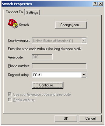
Figure 9 Modify the baud rate

Step8 Select Call/Call to re-connect to the switch.
Figure 10 Connect to the switch
Press Enter, and the following information appears.
The current baudrate is 19200 bps
===============================<BAUDRATE SET>===============================
|Note:'*'indicates the current baudrate |
| Change The HyperTerminal's Baudrate Accordingly |
|---------------------------<Baudrate Available>---------------------------|
|<1> 9600(Default) |
|<2> 19200* |
|<3> 38400 |
|<4> 57600 |
|<5> 115200 |
|<0> Exit |
============================================================================
Enter your choice(0-5):
Step9 Type 0 to return to the serial submenu.
====================<BOOTWARE OPERATION SERIAL SUB-MENU>====================
|<1> Update Full BootWare |
|<2> Update Extend BootWare |
|<3> Update Basic BootWare |
|<4> Modify Serial Interface Parameter |
|<0> Exit To Main Menu |
============================================================================
Enter your choice(0-4):
Step10 Type a number from 1 to 3 as needed. For example, type 1 to upgrade the entire BootWare. The following information appears.
Please Start To Transfer File, Press <Ctrl+C> To Exit.
Waiting ...CCCC
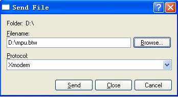
Step11 Select Transfer > Send File in the HyperTerminal window. In the Send File dialog box that appears, click Browse to select the target .btw file, and select Xmodem as the protocol.
Figure 11 Send file dialog box
Step12 Click Send. The following dialog box appears:
Figure 12 Send the file using XMODEM
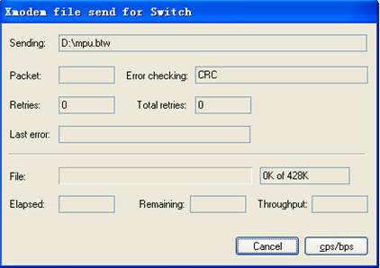
When the download is complete, the following information appears:
Download successfully!
447616 bytes downloaded!
Updating Basic BootWare? [Y/N]
Step13 Type Y to upgrade basic BootWare. After the upgrade is complete, the following information appears.
Updating Basic BootWare.........Done!
Updating Extend BootWare? [Y/N]
Step14 Type Y to upgrade extended BootWare. After the upgrade is complete, the following information appears.
Updating Extend BootWare.........Done!
====================<BOOTWARE OPERATION SERIAL SUB-MENU>====================
|<1> Update Full BootWare |
|<2> Update Extend BootWare |
|<3> Update Basic BootWare |
|<4> Modify Serial Interface Parameter |
|<0> Exit To Main Menu |
============================================================================
Enter your choice(0-4):
Step15 Type 0 to return to the BootWare operation menu, and type 0 in the BootWare operation menu to return to the BootWare menu.
Step16 Type 0 in the BootWare menu to reboot the switch.
|
|
NOTE: After the startup, change the baud rate of the HyperTerminal back to 9600 bps by following Step 6 through Step 8. |
Managing files
You can display files, set system software image type, and delete files from the BootWare menu. Type 4 in the BootWare menu to enter the following file control menu.
========================<File CONTROL>=======================
|Note:the operating device is flash |
| <1> Display All File(s) |
| <2> Set Application File type |
| <3> Delete File |
| <0> Exit To Main Menu |
=============================================================
Enter your choice(0-3):
|
|
NOTE: For how to manage files from the CLI, see the Fundamentals Configuration Guide in the H3C S7500E[S7508E-X] Configuration Guides. |
Display files
Type 1 in the file control menu to display all files.
Display all file(s) in flash:
'M' = MAIN 'B' = BACKUP 'S' = SECURE 'N/A' = NOT ASSIGNED
============================================================================
|NO. Size(B) Time Type Name |
|1 31912384 May/23/2000 144:40:5 N/A main.bin |
|2 4224 Apr/12/2000 08:47:53 N/A private-data.txt |
|3 5764 Apr/12/2000 08:48:09 N/A startup.cfg |
|4 4866 Apr/12/2000 08:48:03 N/A system.xml |
|5 31911744 Apr/06/2000 17:23:33 M S7508E-X.bin |
|6 4 Apr/10/2000 22:11:31 N/A snmpboots |
|7 9176 Apr/11/2000 17:44:02 N/A patch.bin |
|8 1526 Apr/02/2000 01:02:50 N/A patchstate |
|9 5844 Apr/11/2000 22:09:07 N/A test/my_archive_1.cfg |
|10 118773 Apr/11/2000 21:17:30 N/A logfile.log |
============================================================================
===============================<File CONTROL>===============================
|Note:the operating device is flash |
|<1> Display All File(s) |
|<2> Set Application File type |
|<3> Delete File |
|<0> Exit To Main Menu |
============================================================================
Enter your choice(0-3):
Set system software image type
Files fall into M, B, and N/A types. You can modify the type of a file from the BootWare menu.
|
|
NOTE: You cannot change the type for a secure system software image. |
Step1 Type 2 in the file control menu. The following information appears.
'M' = MAIN 'B' = BACKUP 'S' = SECURE 'N/A' = NOT ASSIGNED
============================================================================
|NO. Size(B) Time Type Name |
|1 31912384 May/23/2000 144:40:5 N/A main.bin |
|2 31911744 Apr/06/2000 17:23:33 M S7508E-X.bin |
|0 Exit |
============================================================================
Enter file No:
Step2 Type the number of the target file. The following information appears.
Modify the file attribute:
============================================================================
|<1> +Main |
|<2> -Main |
|<3> +Backup |
|<4> -Backup |
|<0> Exit |
============================================================================
Enter your choice(0-4):
Step3 Type a number from 1 to 4 to set a file type as needed. The following information appears. (“-Main” or “-Backup” means to remove the main or backup attribute of the file. “+Main” or “+Backup” means to set the file as the main or backup system software image.)
Set the file attribute success!
Delete files
Step1 Type 3 in the file control menu. The following information appears.
Deleting the file in flash:
'M' = MAIN 'B' = BACKUP 'S' = SECURE 'N/A' = NOT ASSIGNED
============================================================================
|NO. Size(B) Time Type Name |
|1 31912384 May/23/2000 144:40:5 B main.bin |
|2 4224 Apr/12/2000 08:47:53 N/A private-data.txt |
|3 5764 Apr/12/2000 08:48:09 N/A startup.cfg |
|4 4866 Apr/12/2000 08:48:03 N/A system.xml |
|5 31911744 Apr/06/2000 17:23:33 M S7508E-X.bin |
|6 4 Apr/10/2000 22:11:31 N/A snmpboots |
|7 9176 Apr/11/2000 17:44:02 N/A patch.bin |
|8 1526 Apr/02/2000 01:02:50 N/A patchstate |
|9 5844 Apr/11/2000 22:09:07 N/A test/my_archive_1.cfg |
|10 118773 Apr/11/2000 21:17:30 N/A logfile.log |
|0 Exit |
============================================================================
Enter file No:
Step2 Type the number of the target file. For example, type 9, and the following information appears.
The file you selected is flash:/test/my_archive_1.cfg,Delete it? [Y/N]
Step3 Type Y to delete the selected file. The following information appears.
Deleting.....Done!
Handling upgrade failures
If an upgrade failure occurs, the switch operates using the original version.
Follow these steps to handle upgrade failure:
1. Check that physical ports are correctly connected.
2. Check that the HyperTerminal settings are correct.
3. Check the HyperTerminal output for errors. The following shows some possible errors.
· You have selected a baud rate other than 9600 bps, but did not set to the corresponding baud rate on HyperTerminal.
· You typed an incorrect TFTP server IP address, filename, or directory.
· You typed an incorrect FTP server IP address, filename, file directory, FTP username, or password.
4. Verify FTP or TFTP server software is running and has correct settings.
5. Verify the flash has enough memory to store the downloaded files.
6. Verify that the versions of system software and BootWare are correct. For the compatibility between the system software and BootWare, see the hardware and software compatibility matrix in Release Notes.
7. Verify that the BootWare image is applicable to the target cards.
8. If a message “Something is wrong with the file” appears, check that the file is usable.
Copyright © 2011-2012 Hangzhou H3C Technologies Co., Ltd.
