| Title | Size | Downloads |
|---|---|---|
| H3C LSP5GT8P Interface Card User Manual-5PW101-book.pdf | 315.8 KB |
- Table of Contents
- Related Documents
Overview
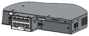
Each LSP5GT8P interface card provides eight 10/100/ 1000Base-T Ethernet ports.
Figure 1 Appearance of the LSP5GT8P interface card
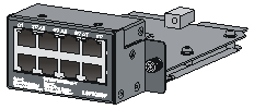
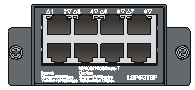
Figure 2 Front panel of the LSP5GT8P interface card
|
|
NOTE: The LSP5GT8P interface card is applicable to multiple models of H3C switches, and the switch models that it applies to may update with time. For the latest information, contact H3C technical support or marketing staff. |
Description of 10/100/1000Base-T Ethernet Ports
Table 1 10/100/1000Base-T Ethernet port specifications
|
Item |
Specification |
|
Port quantity |
8 |
|
Connector type |
RJ-45 |
|
Port standard |
· 10 Mbps, full duplex/half duplex · 100 Mbps, full duplex/half duplex · 1000 Mbps, full duplex · MDI/MDI-X, auto-sensing |
|
Max transmission distance |
100 m (328.08 ft) |
|
Transmission medium |
Category-5 or higher twisted pair cable |
|
Compliance standard |
IEEE 802.3i, 802.3u, 802.3ab |
Description of LEDs
The LSP5GT8P interface card provides a port status LED for each port on the panel. It indicates the working status of a port together with the port mode LED on the switch.
|
Port mode LED on the switch |
Port status LED on the interface card |
Description |
|
Steady green (rate mode) |
Steady green |
The port operates at a rate of 1000 Mbps; the LED is fast flashing when data is being sent and/or received on the port. |
|
Steady yellow |
The port operates at a rate of 10/100 Mbps; the LED is fast flashing when data is being sent and/or received on the port. |
|
|
Flashing yellow (3 Hz) |
POST failed on the port. |
|
|
Off |
The port is not up. |
|
|
Steady yellow (duplex mode) |
Steady green |
The port operates in full-duplex mode; the LED is fast flashing when data is being sent and/or received on the port. |
|
Steady yellow |
The port operates in half-duplex mode; the LED is fast flashing when data is being sent and/or received on the port. |
|
|
Flashing yellow (3 Hz) |
POST failed on the port. |
|
|
Off |
The port is not up. |
|
|
NOTE: Port status LED of the LSP5GT8P interface card is affected by the port mode switching button on your switch. For more information about the port mode switching button, see the installation guide of the switch. |
The following tools are needed for installation and removal:
· Phillips screwdriver
· ESD-preventive wrist strap
|
|
NOTE: The installation tools are not shipped with H3C’s devices. You need to prepare them by yourself. |
Installing the LSP5GT8P Interface Card
Installing the Interface Card to the Switch
|
|
NOTE: The procedure of installing the LSP5GT8P interface card to different models of H3C switches is similar. This manual takes the S5500-34C-HI switch as an example. |
1. Wear an ESD-preventive wrist strap and make sure that the wrist strap has a good skin contact and is properly grounded.
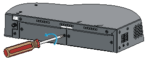
2. Loosen the mounting screws of the filler panel on the interface card slot of the switch, with a Phillips screwdriver and remove the filler panel, as shown in Figure 3.
Figure 3 Install an interface card (I)
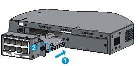
3. Gently push the interface card in along the slot guide rail until the interface card is in close contact with the switch, as shown in callout 1 of Figure 4.
4. Tighten the captive screws with a Phillips screwdriver to fix the interface card, as shown in callout 2 of Figure 4.
Figure 4 Install an interface card (II)
|
|
NOTE: · Keep the removed filler panel properly for future use. · When tightening the fastening screws at both sides of the interface card with a screwdriver or an electric screwdriver, make sure that the torque is not bigger than 0.4 N-m. · When an LSP5GT8P interface card is installed on the switch, the depth of the switch is increased by 34.75 mm (1.37 in), as shown in the Figure 5. |
Figure 5 After an LSP5GT8P is installed
Removing the Interface Card
1. Wear an ESD-preventive wrist strap and make sure that the wrist strap has a good skin contact and is properly grounded.
2. Use a Phillips screwdriver to loosen the captive screws at both sides of the interface card until all spring pressure is released.
3. Pull the interface card towards you along the guide rails, until it completely comes out of the switch chassis.
|
|
CAUTION: When installing or removing an interface card, note the following guidelines: · Do not touch the surface-mounted components directly with your hands. · Do not use excessive force in the operation. · After removing an interface card, if no new interface card is to be installed, install the filler panel as soon as possible to prevent dust and ensure the normal ventilation in the switch. |
Verifying the Installation
When the switch operates properly, check whether the interface card is operating properly according to the status of the Port LED on the LSP5GT8P interface card.
Hangzhou H3C Technologies Co., Ltd. provides customers with comprehensive technical support and service. If you purchase the products from the sales agent of Hangzhou H3C Technologies Co., Ltd., please contact our sales agent or technical personnel.
Address: 310 Liuhe Road, Zhijiang Science Park,
Hangzhou, Zhejiang Province, P. R. China
Postal Code: 310053
Website: http://www.h3c.com
E-mail: service@h3c.com
BOM: 3101A0B5
